The proposed flow chart is as follows: Fig.4: Basic flow chart of system identification using neural network adaptive algorithm. A. NON-LINEAR .... BIOGRAPHY.
ISSN (Print) : 2320 – 3765 ISSN (Online): 2278 – 8875
International Journal of Advanced Research in Electrical, Electronics and Instrumentation Engineering (An ISO 3297: 2007 Certified Organization)
Vol. 3, Issue 3, March 2014
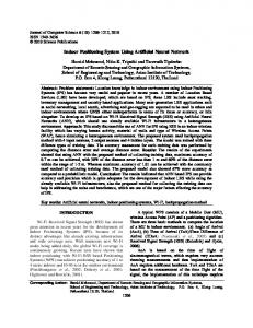
System Identification Using Recurrent Neural Network Santosh Kumar Behera1, Debaraj Rana2 M.Tech Scholar, Dept of ECE, Centurion University of Technology & Management, Bhubaneswar, Odisha, India 1 Asst. Prof. Dept of ECE, Centurion University of Technology & Management, Bhubaneswar, Odisha, India 2 ABSTRACT: A system identification problem can be formulated as an optimization task where the objective is to find a model and a set of parameters that minimize the prediction error between the measured data and the model output. The most existing system identification approaches are highly analytical and based on mathematical derivation of the system’s model. System identification is one of the most interesting applications for adaptive algorithms. We have proposed a recurrent neural network (RNN) based adaptive algorithm, due to its robustness and calculus simplicity. Based on the error signal, the filter’s coefficients are updated and corrected, in order to adapt, so the output signal has the same values as the reference signal. The proposed method is suitable for non-linear system identification. KEYWORDS: System Identification, Neural Network, RNN, Activation Function I.
INTRODUCTION
Within the last several years, there are several different algorithms has been proposed for identification of linear or non-linear system, and these algorithms utilize different forms of knowledge about the system. Such a proposed algorithm is adaptive filter algorithm for system identification using independent component analysis (ICA), which separates the signal from noisy observation under the assumption that the signal and noise are independent [7]. Also we observed an identification method using continuous-time neural network for a nonlinear system in which the system input/output signals is developed for a class of nonlinear systems. The identification algorithm consists of two stages: (i) preprocessing the system input and output data to estimate the state variables in the chosen model coordinate; (ii) neural network parameter estimation [9]. It deals with the basic neural network architectures, the capability of neural networks and shows the motivations why neural networks are applied in system identification [1]. Identifying an unknown system has been a central issue in various application areas such as control, channel equalization, echo cancellation in communication networks and teleconferencing etc. Here, the proposed method state that system identification is performed by adjusting parameters within a given model until its output, for a particular input, coincides as well as possible with the measured output of the system being identified for the same input. After a system h a s been i den t i fi ed , i t s output can then be predicted f o r a given input to the system. This, of course, is usually the p r i m a r y g oa l of the system identification problem. System identification is an important way of investigating and understanding the world around. Identification is a process of deriving a mathematical model of a predefined part of the world, using observations. There are several different approaches of system identification, and these approaches utilize different forms of knowledge about the system. System Identification is the process of determining the model or the equations of motion for your system. The main aim of the system identification is, to determine a mathematical model of a physical or dynamic system for observed data. It is the process of developing or the mathematical representation of a physical system using experimental data. The system identification technique can utilize both input and output data or can include only the output data [2]. System identification is the process of deriving a mathematical model of a system using observed data. Modeling is an essentially important way of exploring, studying and understanding the world around. In system modeling three main principles have to be considered such as separation, selection and parsimony [10]. The most likely hypothesis is the simplest one that is consistent with all Copyright to IJAREEIE www.ijareeie.com 8111
ISSN (Print) : 2320 – 3765 ISSN (Online): 2278 – 8875
International Journal of Advanced Research in Electrical, Electronics and Instrumentation Engineering (An ISO 3297: 2007 Certified Organization)
Vol. 3, Issue 3, March 2014 observations. System Identification is an essential requirement in areas such as control, communication, power system and instrumentation for obtaining a model of a system (plant) of interest or a new system to be developed. For the purpose of development of control law, analysis fault diagnosis, etc. System identification concerns with the determination of a system, on the basis of input output data samples. The identification task is to determine a suitable estimate of finite dimensional parameters which completely characterize the plant. The selection of the estimate is based on comparison between the actual output sample and a predicted value on the basis of input data up to that instant.
Fig.1: Basic System Identification Process II.
NEURAL NETWORK
Neural networks are distributed information processing systems made up of a great number of highly interconnected identical or similar simple processing units, which are doing local processing, and are arranged in ordered topology. An important feature of these networks is their adaptive nature, which means that its knowledge is acquired from its environment through an adaptive process called learning. The construction of neural networks uses this iterative process instead of applying the conventional construction steps of a computing device. It is composed of a large number of highly interconnected processing elements (neurons) working in unison to solve specific problems. The area of Neural Networks probably belongs to the borderline between the Artificial Intelligence and Approximation Algorithms. Think of it as of algorithms for "smart approximation" [16]. The NNs are used in (to name few) universal approximation (mapping input to the output), tools capable of learning from their environment, tools for finding non-evident dependencies between data and so on. Neural networks are typically organized in layers. Layers are made up of a number of interconnected 'nodes' which contain an 'activation function'. Patterns are presented to the network via the 'input layer', which communicates to one or more 'hidden layers' where the actual processing is done via a system of weighted 'connections'. The hidden layers then link to an output layer' as shown in figure -2 [5].
Copyright to IJAREEIE
www.ijareeie.com
8112
ISSN (Print) : 2320 – 3765 ISSN (Online): 2278 – 8875
International Journal of Advanced Research in Electrical, Electronics and Instrumentation Engineering (An ISO 3297: 2007 Certified Organization)
Vol. 3, Issue 3, March 2014
Fig.2: Simple model of an artificial neuron Neural networks are also similar to biological neural networks in performing functions collectively and in parallel by the units, rather than there being a clear delineation of subtasks to which various units are assigned [12]. The term "neural network" usually refers to models employed in statistics, cognitive psychology and artificial intelligence. Neural network models which emulate the central nervous system are part of theoretical neuroscience and computational neuroscience. Neural Networks are a different paradigm for computing: Von Neumann machines are based on the processing/memory abstraction of human information processing. Neural networks are based on the parallel architecture of animal brains. Neural networks are a form of multiprocessor computer system, with Simple processing elements A high degree of interconnection Simple scalar messages Adaptive interaction between elements In neural networks several slightly different elementary neurons are used, however, the neural networks used for system modeling usually apply two basic processing elements. The first one is the perceptron and the second is the basis function neuron. The perceptron is a nonlinear model of a neuron. The NN models used in today engineering applications have a very general structure which allows for use with wide variety of nonlinear functions. A. Recurrent Neural Network: A recurrent network is a network with feedback; some of its outputs are connected to its inputs. This is quite different from the networks that we have studied thus far, which were strictly feed forward with no backward connections. One type of discrete-time recurrent network is shown in Figure-3[18].
Fig.3: Recurrent Neural Network
a(0) = p, a(t+1) = satlins(wa(t)+b) In this particular network the vector P supplies the initial condition (i.e. a(0) = P Then future outputs of the network are computed from previous outputs:
a 1 = satlins Wa 0 + b , a 2 = satlins Wa 1 + b Copyright to IJAREEIE
www.ijareeie.com
(1) 8113
ISSN (Print) : 2320 – 3765 ISSN (Online): 2278 – 8875
International Journal of Advanced Research in Electrical, Electronics and Instrumentation Engineering (An ISO 3297: 2007 Certified Organization)
Vol. 3, Issue 3, March 2014 Recurrent networks are potentially more powerful than feed forward networks and can exhibit temporal behavior. A recurrent neural network (RNN) is a class of neural network where connections between units form a directed cycle. This creates an internal state of the network which allows it to exhibit dynamic temporal behavior. III. PROPOSED METHOD The proposed structure for identification of system has been shown in figure 1. Here we have considered RNN for identification. The proposed flow chart is as follows: DESIGNED KNOWN SYSTEM
UNKNOWN SYSTEM
ERROR ESTIMATION
IS ERROR MINIMISED!
ERROR MINIMISATION
WEIGHT ADJUSTMENT
NO
YES
SYSTEM IDENTIFIED
Fig.4: Basic flow chart of system identification using neural network adaptive algorithm A. NON-LINEAR SYSTEM IDENTIFICATION For identification of non-linear system, we have considered here a Recurrent Neural Network with supervised learning method [6]. Here, we have consider a system as Y (t) = (-0.9y (t-1) +x (t-1))/ (1+y2 (t-1))
(2)
To identify the above system, we have considered two hidden layer with 10 neurons in each of hidden layer. The learning parameter is taken to be 0.5. Here, we have used an activation function called sigmoid function, given as
f (x) =1/ (1+e-x)
(3)
This will provides a graded, non-linear response within a specified range. The weights are randomly initialized and updated in each iteration [11]. We have taken randomly 500 iterations and the system is identified with successful results. B. LINEAR SYSTEM IDENTIFICATION: For identification of linear system, we have proposed the same architecture as like nonlinear system with same learning method. Here, we have consider a system as
Y (t) = x (t) +x (t-1)-0.03x (t-1)
(4)
Here, also we have considered two hidden layers with 10 neurons each. In this case weights are initialized randomly and updated itself and after 1000 iterations, the system is identified.
Copyright to IJAREEIE
www.ijareeie.com
8114
ISSN (Print) : 2320 – 3765 ISSN (Online): 2278 – 8875
International Journal of Advanced Research in Electrical, Electronics and Instrumentation Engineering (An ISO 3297: 2007 Certified Organization)
Vol. 3, Issue 3, March 2014 IV.
RESULTS
A. FOR NON-LINEAR SYSTEM IDENTIFICATION:
Fig.5: Output of the system and RNN during training
Fig.6: Error between system and RNN during training
Number of hidden layers=2 Number of neurons N1=N2=10 Learning parameter nn=0.5
Fig.7: Error par epoch
Copyright to IJAREEIE
Fig.8: Output of the system and RNN during testing
Fig.9: Error between output of the system and RNN during testing www.ijareeie.com
8115
ISSN (Print) : 2320 – 3765 ISSN (Online): 2278 – 8875
International Journal of Advanced Research in Electrical, Electronics and Instrumentation Engineering (An ISO 3297: 2007 Certified Organization)
Vol. 3, Issue 3, March 2014
During training phase, the system and RNN output has been shown in figure-5. We have shown both outputs for 50 iterations. And error between system output and RNN output has been shown in figure-6. The maximum error found to be 0.05. The error per epoch has been shown in figure-7, which says that system is identified around 300 iterations. During testing phase, the both output of RNN and system has been shown in figure -8 and the corresponding error is shown in figure-9. It is found that maximum error occurs found in testing phase, is around 1.0. A. FOR LINEAR SYSTEM IDENTIFICATION: The output of the system and RNN During the training
The Error between the system and RNN During the training
2
0.8
1.8
0.6
1.6
0.4 1.4
0.2 1.2 1
0
0.8
-0.2
0.6
-0.4
0.4
-0.6
0.2
-0.8 0
0
5
10
15
20 25 30 Time par Epoch
35
40
45
50
-1
Fig.10: Output of the system and RNN during training
0
5
10
15
20 25 30 Time par Epoch
35
40
45
50
Fig.11: Error between system and RNN during training the output of the system and RNN
Error for each Epoch 2
5.5
1.5
5 1
4.5
0.5 0
4 -0.5
3.5
-1 -1.5
3
-2
2.5
0
100
200
300
400 500 600 Time of training
700
800
900
0
10
20
30
1000
Fig.12: Error par epoch
40
50 60 Time scale
70
80
90
100
Fig.13: Output of the system and RNN during testing The Error between the output of the system and RNN
0.5
0
-0.5
-1
-1.5
-2
-2.5
-3 0
10
20
30
40
50 60 Time scale
70
80
90
100
Fig.14: Error between output of the system and RNN Copyright to IJAREEIE
www.ijareeie.com
8116
ISSN (Print) : 2320 – 3765 ISSN (Online): 2278 – 8875
International Journal of Advanced Research in Electrical, Electronics and Instrumentation Engineering (An ISO 3297: 2007 Certified Organization)
Vol. 3, Issue 3, March 2014 Number of hidden layers=2, Number of neurons N1=N2=10, Learning parameter nn=0.2 During training phase, the system and RNN output has been shown in fig-10. We have shown both outputs for 50 iterations. And error between system output and RNN output has been shown in figure-11. The maximum error found to be 0.6. The error per epoch has been shown in figure-12, which says that system is identified around 800 iterations. During testing phase, the both output of RNN and system has been shown in figure -13 and the corresponding error is shown in figure-14. It is found that maximum error occurs found in testing phase, is around 0.5. V.
CONCLUSION
Here, the identification of both systems has been done, where we have proposed a RNN adaptive algorithm to identify both linear and non-linear system. The proposed architecture consists of two hidden layers, each with 10 neurons. From the result itself it justify that the proposed method is suitable for identification of non-linear system. The error par epoch shows the correctness of identification. In future, we have planning to identify some more system and develop the comparative analysis among them.
REFERENCES [1]
G. C. Goodwin and R. L. Payne,” Dynamic System Identification”, Academic Press, New York, 1977. Soderstrom, T. and Stoica, P.”System Identification”, Prentice Hall, 1989. Kristinsson, K. And Dumont, G.A. "System identification and control using genetic algorithms". Systems, Man and Cybernetics, IEEE Transactions on (Volume:22 , Issue: 5 ), Page(s):1033 - 1046 Sep/Oct, 1992 [4] Narendra K. S. and Parthasarathy K., “Identification and control of dynamic systems using neural networks‖”, IEEE Trans. on Neural Networks, vol. 1, Mar, 1990. [5] Haykin S.,”Neural Networks: A comprehensive Foundation‖”, Pearson Edition Asia, 2002. [6] Nagumo, J.; Noda, A. “A learning method for system identification”, l IEEE Transactions on volume: 12, Issue: 3 Digital Object Identifier: 0.1109/TAC.1967.1098599 Publication Year: 1967. [7] Jun-Mei Yang , H. Sakai, “A New Adaptive Filter Algorithm for System Identification using Independent Component Analysis”, Acoustics, Speech and Signal Processing, IEEE International Conference on (Volume: 3 ),ICASSP 2007. [8] Kumon, T. Iwasaki, M. ; Suzuki, T. ; Hashiyama, T. ; Matsui, N. ; Okuma, S., Nonlinear system identification using genetic algorithm, Industrial Electronics Society, 26th Annual Confjerence of the IEEE (Volume:4 ) , IECON 2000. [9] Yong Liu Zhu, J.J. ,”Continuous-time nonlinear system identification using neural network” , American Control Conference, 2008. [10] L. Ljung, “System Identification - Theory for the User”, Prentice-Hall, N.J. 2nd edition, 1999. [11] P. Eykhoff, “System Identification, Parameter and State Estimation”, Wiley, New York, 1974. [12] M. H. Hassoun, “Fundamentals of Artificial Neural Networks”, MIT Press, Cambridge, MA. 1995. [13] M. Brown and C.Harris, “Neurofuzzy Adaptive Modelling and Control”, Prentice Hall, New York, 1994. [14] R. J. Williams and D. Zipser, “A Learning Algorithm for Continually Running Fully Recurrent neural network, Neural Computation”, Vol. 1.. pp. 270-280, 1989. [15] N. Murata, S. Yoshizawa and Shun-Ichi Amari, “Network Information Criterion – Determining the number of Hidden Units for an Artificial Neural Network Model” , IEEE Transactions on Neural Networks, Vol. 5, No. 6, pp. 865–872, November 1 9 9 4. [16]J.-S. R. Jang, C.-T. Sun, E. Mizutani. "Neuro-Fuzzy and Soft Computing, A computational Approach to Learning and Machine Intelligence".Matlab Curriculum Series. Prentice Hall. 1997. [17] S. Haykin, “Neural Networks- A comprehensive foundation”, Second Edition, Prentice Hall, N. J.1999. [18] http://hagan.okstate.edu/2_Architectures. [2] [3]
BIOGRAPHY Mr. Santosh Kumar Behera, working as lecturer in Department of Electronics & Telecommunication. Biit Group of Institution,Bhubaneswar. He has three years plus of teaching experience in various technical colleges of Odisha. He has done his B.Tech from Biju Pattnaik University of Technology, Odisha and completed in the year 2010 and continuing Master Degree from Centurion University of Technology & Management, Jatni, and Odisha during 201214. Mr. Debaraj Rana, working as Asst. Professor in the Department of Electronics & Communication Engineering, CIT Jatni. He has two years of Research Experience. He has completed his B.Tech from Biju Pattnaik University of Technology, Odisha and in the year 2007 and Master Degree from VSS University of Technology, Burla, Odisha during 2009-11. He has two numbers of IEEE International Conference Publications on his credit. Presently He is doing Research on Face Analysis (Image Processing) and Different Optimization Technique (Soft Computing).
Copyright to IJAREEIE
www.ijareeie.com
8117