Email: {hayajneh, prashant, dtipper, tkim}@sis.pitt.edu ... The sender typically believes that the forwarded packet was lost ... the sender will timeout and assume that a collision occurred. .... medium to be free, the node sends an RTS packet.
Detecting Malicious Packet Dropping in the Presence of Collisions and Channel Errors in Wireless Ad hoc Networks Thaier Hayajneh, Prashant Krishnamurthy, David Tipper, and Taehoon Kim Graduate Networking and Telecommunications Program University of Pittsburgh, Pittsburgh, PA, USA Email: {hayajneh, prashant, dtipper, tkim}@sis.pitt.edu
Abstract—Detecting malicious packet dropping is important in ad hoc networks to combat a variety of security attacks such as blackhole, greyhole, and wormhole attacks. We consider the detection of malicious packet drops in the presence of collisions and channel errors and describe a method to distinguish between these types. We present a simple analytical model for packet loss that helps a monitoring node to detect malicious packet dropping attacks. The model is analyzed and evaluated using simulations. The results show that it is possible to detect malicious packet drops in the presence of collisions and channel errors.
I. I NTRODUCTION Nodes in ad hoc networks rely on other nodes to forward and route data packets to the destination. Malicious nodes can exploit this situation and disrupt ad hoc network operation by dropping data packets and not delivering them to the next hop. In its obvious version, a malicious node will simply discard all the data packets that it is supposed to relay (this is referred to as the black hole attack [1]). The nodes in an ad hoc network communicate using wireless links which are by nature vulnerable to interference and channel errors that may corrupt some or many data packets. Moreover, the nodes share the physical medium, compete to transmit data packets and suffer collisions. Thus, one of the problems in detecting malicious nodes that drop packets is that it may not be clear as to whether the packet was dropped due to channel errors, collisions, or due to malicious intent. In most detection mechanisms, the number of packets that are not forwarded is recorded by a passive listener. A threshold on the number of dropped packets is then used to decide whether or not a node is malicious. Depending on the threshold and data load, a burst of errors on the channel or an increase in the number of collisions can trip the threshold creating false alarms. As described in the next section, previous work on distinguishing between causes for dropped packets considered only collisions and channel errors [2]–[5] and ignored malicious packet drops. On the other hand, protocols that detect malicious packet dropping [6]–[8] ignored collisions and channel errors. In this paper we adopt a unified approach to packet loss considering collisions, channel errors, and malicious packet drops. We consider two possibilities for a malicious node. First, it aims to disrupt network operation by not relaying a packet to the next hop. In this case the node will acknowledge the packet to the sender. The sender typically believes that the
forwarded packet was lost due to some natural reason (collision or channel error). Second, the malicious node intends to drain the energy of a node. Here the malicious node will not acknowledge receipt of a packet. The sender retransmits the data packet unnecessarily several times expending energy. The rest of the paper is organized as follows. Section II describes related work on distinguishing between causes for packet drops and detection of malicious nodes that drop packets. Section III provides the framework used to determine the probability that a node is malicious. Section IV presents the performance evaluation and Section V discusses the limitations and concludes the paper. II. R ELATED W ORK Related work in this area assumes 802.11-like nodes. We assume that the reader is familiar with 802.11 access procedures. A classification of the types of interference that impacts packet loss was presented in Ma et al. [9]. In Type-1 interference, the interference signal arrives prior to the desired signal. In Type-2 interference, the interference signal arrives after the desired signal, and in the case of collisions, both signals arrive at the same time. Statistics computed at each node are used to determine the packet loss rate due to each type of interference. Pang et al. [2] distinguished between packet loss due to collisions and link errors. The main idea is that shorter RTS/CTS and MAC headers in 802.11 are less vulnerable to errors than data. Thus, during the RTS/CTS access procedure, errors are assumed to be due to collisions. If the node receives the CTS frame but not the ACK frame then the transmission has more likely failed due to a channel error. However, if an RTS/CTS frame is not received, then the transmission more likely failed due to a collision. If a basic access procedure is used, the sender depends on feedback from the receiver to determine the cause of packet loss. If a packet with a corrupted header is received, the receiver sends nothing and the sender will timeout and assume that a collision occurred. If a packet with a correct header is received but the data part is corrupted, the receiver can recognize the sender and reply with a NAK frame. Here, the sender will assume that the packet was lost due to channel errors. The collision aware rate adaptation (CARA) scheme in [3] depends on RTS probing to differentiate collisions from channel errors. The technique is
2
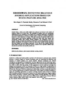
III. D ISTINGUISHING C AUSES FOR PACKET L OSS A. Overview In Fig. 1 we present a comprehensive overview for causes of packet loss in ad hoc networks. In general, a packet is sent from node A to node B. The expectation is that node B will relay it to the next hop which is either the destination or a node along the route to the destination. The packet is either received or not received by node B. There are several causes that may prevent a packet from being received. If Node B’s buffer is full then it cannot accept any new packets and drops them. Some packets may be corrupted due to channel error which makes them unreadable and will be dropped by node B. Since nodes in ad hoc network mainly use Carrier Sense Multiple Access/Collision Avoidance (CSMA/CA), packets may collide. Collisions may be natural or intentional. Natural collisions may happen when two nodes attempt to access the medium at the same time. Later we will show that collisions in ad hoc networks also depend on the traffic rate. When two or more packets collide they will both be corrupted and not received at node B. Intentional collisions can be caused by a node C that does not adhere to the rules of the MAC layer protocol. These attacks are considered as MAC misbehaving attacks [12] or as jamming. Finally, jamming attacks [13] can prevent a packet from being received. If a packet is received at node B then it may be forwarded correctly to the next hop, which is the best case. Node B may maliciously attempt to corrupt the packet and then forward
Packet is sent
Packet is Received
Packet is not Received
Forwarded after corruption
Forwarded Correctly
Dropped Maliciously
Fig. 1.
Jamming or Misbehavior
Buffer overflow
Collisions & Channel Errors
Overview of packet loss
PC RTS-col 1
IDLE
PC .(1-PC) 1
Collision Model
similar to the one presented in [2] in assuming causes of packet drops. Malone et al [5] presented a technique to estimate packet losses caused by collisions and by channel errors. The technique requires the knowledge of some statistics such as the number of successful transmissions out of the total transmissions over some period of time and the number of slots in which the station does not transmit. Next we look at detecting malicious packet dropping attacks. We do not consider reputation schemes and watchdoglike schemes (see for e.g., [10]) in detail as they do not distinguish between types of packet losses. Other work such as [6] use probes disguised as normal packets to detect malicious nodes and [7] considers a centralized authority that receives reports on statistics of various IP flows. Neither distinguishes between causes for packet loss. Differentiating malicious drops from overflow of buffer space in relay nodes in an ad hoc network is considered in [11]. The assumption is that packets are either maliciously dropped by a bottleneck node or due to buffer overflows. The sender S’s traffic rate is λ to receiver R through a bottleneck node X together with other traffic. Node X has a finite buffer size B which is assumed to be known to its neighbors. The empirical probability of packet loss at node X (number of dropped packets)/(number of sent packets) is compared to the loss for a Poisson source using an Erlang Prate B formula: (Λ/µ)B / k=0 (Λ/µ)B . If the empirical probability is significantly greater than the predicted probability, then node R suspects that node X is maliciously dropping packets. We do not consider buffer overflows in this paper and use very large buffer sizes in the simulations.
CTS-col
Pt 1 1
Forwarded Correctly
1
PCorrect
Transmit Data
Pe
Channel Error
Pm 1 Malicious Drop
Ack
Fig. 2.
State diagram of packet loss
it or forward a modified version of the packet. Node B may avoid acknowledging the packet to drain node A’s battery. The packet may also be maliciously dropped by node B, and our goal in this is to detect these two malicious activities. Assumptions and Scope of this paper: MAC misbehaving attacks [12] and jamming attacks [13] are considered beyond the scope of our work. We assume that a malicious node will either drop a packet or forward it correctly. We do not consider the case where a malicious node may forward corrupted packets to the next hop. Integration of MAC misbehavior, jamming, and forwarding of corrupted packets into our frame work is part of ongoing work. B. General Framework A state diagram for the different causes of packet loss that we consider is shown in Fig. 2. In the beginning the system will be in an idle state in which the node will be waiting for a packet to send. When a packet arrives, after sensing the medium to be free, the node sends an RTS packet. The system may move to an RTS-collision (RTS-col) state when two or more nodes that are within each other’s range transmit an RTS at the same time. This occurs with probability PC . The system may move to a CTS-col state when a hidden node (not in the transmitting node’s range but within the range of the receiving node) transmits something that collides with the CTS sent by the receiving node. CTS-col will also happen with probability PC but will only happen if there is no RTS collision, thus CTS-col will occur with probability (1 − PC )PC . A node will transmit a packet only if it receives a CTS reply to its RTS, that is, the Transmit data state will be reached if neither RTScol nor CTS-col are the previous states. Thus the probability
3
that a data packet is transmitted Pt , is: Pt = (1 − PC )(1 − PC .(1 − PC )) = 1 − 2PC + 2PC 2 − PC 3 The assumptions here are that the size of the RTS/CTS packets is small (also transmitted at the lowest data rate: 1 Mbps) and if either was not delivered correctly then most probably a collision occurred (this was also assumed in [2], [3]). After a packet is transmitted it will be either forwarded with probability PCorrect , lost due to channel errors with probability Pe , or maliciously dropped or not ACK-ed with probability Pm . Packets that are maliciously dropped may or may not be acknowledged. In the state diagram we assume that dropped packets will be acknowledged. Thus, a system that is in the Malicious Drop state will move to the ACK state if an ACK message is sent or return to the Transmit state if no ACK is sent. Packets lost due to channel errors will also not be acknowledged by the receiver, and will be retransmitted after some timeout. That is, when the Channel Error state is reached, the system will definitely return back to the Transmit state. For a packet to be received and forwarded correctly it must satisfy the following conditions: (i) it must be transmitted by the sender (ii) it must not be dropped due to channel errors (iii) it must not be maliciously dropped. Thus the probability to forward a packet correctly PCorrect can be computed as: PCorrect = Pt (1 − Pe )(1 − Pm )
(1)
Our goal is to solve this equation and find an estimated value of Pm . In what follows, we describe how nodes can estimate the values for PC , Pe , and PCorrect . In Section IV, we also consider the impact of wrong estimates. We note here that the state diagram assumes a steady state, that we are not strictly verifying whether the states are memoryless or not, and that we make several simplifying assumptions here (e.g., the limit on the number of retransmissions is not considered). The state diagram is not used analytically otherwise here, but is used to clarify the assumptions. In case RTS/CTS procedures are not employed, feedback to the sender based on header/data corruption as in [2] can be employed. However, we have not considered this approach in this paper. Collisions: One way of estimating PC is to use available analytical work. Collisions in 802.11 have been extensively analyzed by researchers. The most cited reference by Bianchi [14] and a related reference with modified assumptions [15] both used a complicated Markov chain model. In most of the analysis, an IEEE 802.11 infrastructure network with an access point is assumed. We assume an ad hoc configuration in which each node will only compete with neighbors that are within its transmission range and use simpler estimates. In [16], linearization was used to find an approximate value for PC that depends only on the contention window W and the number of nodes n, and is given by: 2W (n − 1) PC = (W + 1)2 + 2W (n − 1) Using this equation, PC is more than 50% if the number of nodes in the wireless LAN exceeds 20 nodes. In our simulations we have n = 13 and W = 31. This will estimate PC = 0.421 (PC = 0.24 if only neighbors are considered with
n = 6 for node 2 in Fig. 3). If we follow the analysis similar to [17], the probability of collision is Pc = 1 − (1 − τ )n−1 where n is the average number of contending nodes and τ is the average probability that a node sends a packet (approximately once every W if nodes always have packets to send). Thus we have: τ = 1/W and the probability of collision can be approximated as: PC = 1 − (1 − 1/W )n−1 For n = 6 and W = 31, PC = 0.15 which is close to the result in Fig. 4 for packets arriving every 0.1s. In all of the above approximations, PC is not related to the traffic rate and it is overestimated. Unfortunately, PC is actually related to the traffic rate as our simulations show in Section IV. Thus the approach we use is for nodes to count the number of RTS and CTS packets seen. A node sends an RTS packet after sensing the media to be free. Then the node will wait for a CTS packet and if it is not received within its specified time period then the number of packets lost due to collisions will be increased. Using the number of RTS and CTS packets that were counted during a time window w the probability that a packet was lost due to collision can be computed as: PC = (#RT S − #CT S) /#RT S
(2)
Channel errors: To model the channel error, the wireless channel is assumed to be a two state Markov chain with alternating good and bad states. This approach has been also used in [18] to analyze the performance of 802.11. The good and bad state durations are assumed to be exponentially and λ−1 distributed with means λ−1 g b , respectively. In [19] researchers performed exhaustive experiments and modeled 802.11 links to find the values of λ−1 and λ−1 for several g b PHY layer bit rates and three SNR levels (high, medium, and low). In this paper we use model parameters from [19] for 11 Mbps links at high SNR (around 32 dB) where the good and bad state mean durations are 0.08s and 0.0003s respectively. The model in [19] is a coarse model that can be used as is with some knowledge of operating data rates and SNR conditions by nodes. A priori training may also be used to estimate these parameters. In this case, Pe = 0.0003/0.0803 = 0.37%. Models for medium and low SNRS are not expected to change our conclusions. Energy Drain Attack: In this case, a malicious node intends to drain the senders battery by not sending ACKs and making the sender retransmit several times before sending an ACK. When the malicious node responds with an ACK to a data packet, the sender node will assume that the packet has been received and0 forwarded correctly. In this case, the sender node estimates PCorrect as: 0
PCorrect = #ACK/#RT S
(3)
The malicious node may drop the ACK-ed packet and not relay it to the next hop, but because the attack is directed towards draining the battery, the ultimate fate of the ACK-ed packet is not relevant. We note that overhearing may drain the battery as well, but leave consideration of this problem for the future.
4
C. Protocol Description We now present the steps that a sending node A will use to detect if its neighbor node B is maliciously dropping packets. Step(1): Node A will count the RTS messages it sent to node B during some time window w and also the CTS messages received from node B during the same time. Node A will use equation (2) (or the analytical overestimates) to compute PC . Step (2): Node A will use the model previously described for the value of Pe based on the link SNR. We assume symmetric links, and thus the SNR is expected to be equal at the sending and receiving sides. Step (3): If the goal of node A is only to prevent0 energy drain attacks then equation (3) is used to compute PCorrect . Step (4): If the goal of node A to detect malicious packet dropping then it will0 use monitoring through overhearing to get an estimate of PCorrect . Step(5): Node A will use equation (4) to compute the percentage of packets being maliciously dropped. If Pm is greater than some threshold value (which will be estimated later using the simulations) then the node is marked as being malicious and node A will take appropriate steps (inform other neighbors, remove it from routes, etc.).
number of nodes Routing Protocol Data rate Queue size Tx. range MAC layer protocol Simulation time Traffic type Packet size packet interval
13 DSR 11 Mbps infinity 250 m 802.11 500 sec CBR 512 B 0.25 sec
TABLE I S IMULATION PARAMETERS
12
8 0
4 1
2
3
5
7 6
9
11 10
Fig. 3.
Simulated Nentwork
3. We have 12 CBR traffic flows between different nodes as follows: 0 to 9, 1 to 9, 1 to 10, 1 to 12, 2 to 9, 2 to 10, 2 to 11, 2 to 12, 3 to 10, 3 to 11, 3 to 12, and 4 to 11. Each CBR traffic flow starts at a different time. Each of nodes 5, 6, 7, and 8 has 3 CBR traffic flows that goes through them. The goal of the simulation is to have node 2 use the protocol described in the previous section to check if any of nodes 5, 6, 7, and 8 is maliciously dropping packets (or draining battery). Node 2 monitors links: 2-5, 2-6, 2-7, and 2-8. In the simulations, we made node 6 intentionally drop a specific percentage of packets that go through it, however, nodes 5, 7, and 8 will not intentionally drop any packets. The simulation parameters that we used are shown in Table I (other parameters were default for ad hoc networks in ns2). The channel error model described in section III.B was implemented in ns-2. RTS and CTS packets were always received correctly. 0.16 0.14 0.12 0.1
Prob. of Colliision
Malicious Dropping Attack: In this case, the malicious receiving node may send an ACK message upon receiving a packet to be relayed and not forward the packet to the next hop. There are two possible ways to know if the acknowledged packet was forwarded or not, either by monitoring the node using overhearing capability (see [20] or [10]) or by having feedback from other nodes that are on the route to the destination. Feedback from other nodes will include communication overhead and is not instant. In this paper we prefer to monitor the receiving node. The node overhears the packets sent by the malicious receiver and detect which packets were forwarded 0 to the next hop nodes and computes the value of PCorrect . Probability of malicious packet dropping: The probability of packet loss due to malicious packet dropping is computed by a sending node using equation (1). Pe and PC are computed as discussed previously. To find an approximate value for Pm 0 the node uses the estimated value of PCorrect . Thus Pm can be computed as: ( � ) � � � 0 0 γ − PCorrect /γ, if γ − PCorrect > 0 Pm = 0 , Otherwise (4) where γ = (1 − 2PC + 2PC2 − PC3 )(1 − Pe ) The idea here is that if there is no malicious packet 0 dropping, the estimated PCorrect should take into account the potential natural causes for packet drops through γ. The probability of packet loss due to malicious packet dropping is computed and if this value is greater than some threshold value then the node is suspected to be maliciously dropping packets.
0.08 0.06 0.04 0.02 0
IV. P ERFORMANCE E VALUATION The performance of our protocol to detect malicious packet dropping is evaluated in this section using simulations. We used ns-2 to simulate the network configuration shown in Fig.
0
0.1
0.2
0.3
0.4
0.5
0.6
Packet interval (s)
Fig. 4.
Collisions for different traffic loads
Fig. 4 shows the probability of collisions for different traffic
5
25 Computed Pm m percentage
loads. The probability of collision PC was computed by node 2 by counting the number of RTS packets it sent, the number of CTS packets it received, with (2). As shown in Fig. 4, the smaller is the packet inter-arrival time, the more is the load and thus there is a higher probability of collision. The simulation was repeated 100 times and 95% confidence intervals are shown in Fig. 4. For all the other simulations we used packet intervals of 0.25 seconds which results in approximately a 2% collision probability. 0.5
20 15 10
MD ED
5
1 % threshold
0
0.45
0
0.4
5
10
15
20
25
Specified Pm percentage
0.35 0.3 0 25 0.25
Fig. 6.
Channel Error %
0.2
Computed Pm percentage
0.15 0.1
14
0.05 Link 2‐6
Fig. 5.
Link 2‐7
Link 2‐8
Channel Error %
Fig. 5 Shows the percentage of channel errors for the links: 2-5, 2-6, 2-7, and 2-8 in the simulations as seen by node 2 when it communicated with nodes 5, 6, 7, and 8, respectively. We used 95% confidence intervals. While we initially assume that node 2 uses the value 0.37 from the channel model, we consider the impact of making errors in this value later. Node 2 follows the steps of the protocol described in section III.C and computes Pm to check if any of nodes 5, 6, 7, or 8 is maliciously dropping packets or trying to drain its energy by asking for unnecessary retransmissions. The simulation results show that the computed Pm for nodes 5, 7, and 8 were almost zero. Thus there are no false alarms with this approach. Node 6 intentionally drops 2, 5, 10, 15, and 25 percent of the data packets that pass through it (going from node 2 to node 10). In this case, the values of Pm computed by node 2 are shown in Fig. 6. Again, the simulation was repeated 100 times and we used 95% confidence intervals. Fig.6 shows the “computed” Pm percentage values at node 2 for the energy drain attack (ED) and malicious dropping (MD) as a function of simulation “specified” malicious packet (or ACK) dropping levels. The match is not exact, but the computed Pm value tracks the actual packet drop values. We set a threshold value of 1% – that is if the “computed” Pm is greater than 1% then the node being monitored is suspected to be maliciously dropping packets. The results in Fig. 6 show that the protocol can detect any node that is maliciously dropping more than 4% of the packets that goes through it (MD case). Energy drain attacks that make the sender retransmit more than 2% of the packets are also detected with this threshold. The MD case in which node 6 is dropping only 2% of the packets is not detected by the protocol as the computed Pm percentage is less than 1%. We believe that detecting malicious packet dropping that is more than 4% is very reasonable, as smaller percentages are likely to cause less serious damage to the network operation. Fig.7 shows how sensitive our protocol is to estimation errors in Pe . The actual estimated value of Pe should be
MD with Pe=0% MD with Pe=4% MD with Pe=8% MD with Pe=10% 1 % threshold
12 10 8 6 4 2 0 0
2
4
6
8
10
12
14
16
Specified Pm percentage
Computed Pm percentage with different estimated Pe values
Fig. 7. 50
MD with Pc=1% MD with Pc=5% MD with Pc=10% MD with Pc=20% MD with Pc=33% 1 % threshold
45 Computed Pm m percentage
Link 2‐5
Computed Pm m percentage
0
40 35 30 25 20 15 10 5 0 0
10
20
30
40
50
Specified Pm percentage
Fig. 8.
Computed Pm percentage with different estimated PC values
around 0.37%. Fig.7 shows the values of the “computed” Pm as a function of the actually “specified” simulation value for different (erroneous) estimates of Pe while the real Pe was 0.37%. The assumption here is that node 2 made errors in estimating the value of Pe either because of using an incorrect model or because the channel changed in between. If node 2 underestimates Pe , the sensitivity of the protocol is improved, as lower Pm values can be detected (but this may also cause false alarms when Pe is large - medium or low SNRs and is estimated to be smaller). If Pe is overestimated significantly
6
(e.g., 10% instead of 0.37%), the protocol can detect a node that drops more than 12% of the data packets. Similarly, Fig.8 shows the sensitivity of the protocol to estimation errors in PC . The real PC value computed by node 2 using equation (3) is 2%. If however, as shown in Fig.8, a higher estimated value of PC is used (e.g., based on the analytical models), the protocol becomes less sensitive. For instance, if PC is mistakenly estimated to be 33% then only packet dropping of 50% can be barely detected. In summary, the estimated average numbers of collisions and channel errors together determine the extent to which malicious drops can be detected. Good estimates can detect very small percentages of malicious packet drops. Threshold value: In our simulations, we have used a 1% threshold value for a traffic rate that results in PC ∼ = 0.02 and used a channel error model with Pe ∼ = 0.0037. However, for different traffic loads for situations that have higher interference and higher Pe , a threshold of 1% may be too low. It is possible to use a higher threshold value at the expense of the ability to detect lower levels of packet drops. For example, a threshold value of 10% will ignore “computed” drops that are less than 10% but produce low, if any, false positives. Using a higher threshold value (≥ 50%) is still useful to detect higher malicious packet drop rates (e.g., black hole attacks). V. D ISCUSSION AND C ONCLUSION The problem of distinguishing between the different causes for packet drops is not simple as the causes may overlap with each other. Moreover, the problem of packet loss is nonstationary (the causes may change with time). For instance, collisions are related to the network traffic at that time, channel errors depend on signal fading and shadowing, which depend on the environment and has inherent randomness. Mobility will make the problem even harder, as malicious nodes may move and make it more difficult to predict the cause of packet loss. Route changes due to excessive drops are possible. While we believe the assumptions about distinguishing causes for packet drops based on RTS/CTS is reasonable, it is likely that RTS/CTS packets may also be lost due to errors and may not entirely prevent collisions of data packets. Finally, the topology we have used is limited in size and scope and results for random/grid like topologies are necessary. Investigation of these issues is part of ongoing work as also is the possibility of using measurements to verify this framework. In this paper, we present a simple method to distinguish between natural causes for packet drops by a node (collisions and channel errors) as against malicious packet drops by a relay node in an ad hoc network. If nodes can have reasonable estimates for collision probabilities and channel error probabilities, even fairly low levels of malicious packet drops can be detected significantly. Underestimates of the natural causes can cause false alarms while overestimates can allow some malicious packet drops to be undetected. ACKNOWLEDGMENTS This research was supported in part by the Army Research office MURI grant W911NF-07-1-0318. The authors thank anonymous reviewers for their comments to improve the paper.
R EFERENCES [1] Y.-C. Hu, A. Perrig, and D. B. Johnson, “Ariadne: a secure on-demand routing protocol for ad hoc networks,” Wirel. Netw., vol. 11, no. 1-2, pp. 21–38, 2005. [2] Q. Pang, S. Liew, and V. Leung, “Design of an effective lossdistinguishable mac protocol for 802.11 wlan,” Communications Letters, IEEE, vol. 9, no. 9, pp. 781–783, Sep 2005. [3] J. Kim, S. Kim, S. Choi, and D. Qiao, “Cara: Collision-aware rate adaptation for ieee 802.11 wlans,” INFOCOM 2006. 25th IEEE International Conference on Computer Communications. Proceedings, pp. 1–11, April 2006. [4] J.-H. Yun and S.-W. Seo, “Novel collision detection scheme and its applications for ieee 802.11 wireless lans,” Computer Communications, vol. 30, no. 6, pp. 1350–1366, —2007—. [5] D. Malone, P. Clifford, and D. J. Leith, “Mac layer channel quality measurement in 802.11,” Communications Letters, IEEE, vol. 11, no. 2, pp. 143–145, Feb. 2007. [6] M. Just, E. Kranakis, and T. Wan, “Resisting malicious packet dropping in wireless ad hoc networks,” in In Proc. of ADHOCNOW03. Springer Verlag, 2003, pp. 151–163. [7] F. Anjum and R. Talpade, “Lipad: lightweight packet drop detection for ad hoc networks,” Vehicular Technology Conference, 2004. VTC2004Fall. 2004 IEEE 60th, vol. 2, pp. 1233–1237 Vol. 2, Sept. 2004. [8] O. F. Gonzalez, M. P. Howarth, and G. Pavlou, “Detection of packet forwarding misbehavior in mobile ad-hoc networks.” in WWIC, ser. Lecture Notes in Computer Science, F. Boavida, E. Monteiro, S. Mascolo, and Y. Koucheryavy, Eds., vol. 4517. Springer, 2007, pp. 302–314. [Online]. Available: http://dblp.uni-trier.de/db/conf/wwic/ wwic2007.html#GonzalezHP07 [9] H. Ma, J. Zhu, and S. Roy, “On loss differentiation for csma-based dense wireless network,” Communications Letters, IEEE, vol. 11, no. 11, pp. 877–879, November 2007. [10] S. Marti, T. J. Giuli, K. Lai, and M. Baker, “Mitigating routing misbehavior in mobile ad hoc networks,” in MobiCom ’00: Proceedings of the 6th annual international conference on Mobile computing and networking. New York, NY, USA: ACM, 2000, pp. 255–265. [11] W. Zhang, R. Rao, G. Cao, and G. Kesidis, “Secure routing in ad hoc networks and a related intrusion detection problem,” Military Communications Conference, 2003. MILCOM 2003. IEEE, vol. 2, pp. 735–740 Vol.2, Oct. 2003. [12] S. Radosavac, A. A. C´ardenas, J. S. Baras, and G. V. Moustakides, “Detecting ieee 802.11 mac layer misbehavior in ad hoc networks: Robust strategies against individual and colluding attackers,” J. Comput. Secur., vol. 15, no. 1, pp. 103–128, 2007. [13] W. Xu, W. Trappe, Y. Zhang, and T. Wood, “The feasibility of launching and detecting jamming attacks in wireless networks,” in MobiHoc ’05: Proceedings of the 6th ACM international symposium on Mobile ad hoc networking and computing. New York, NY, USA: ACM, 2005, pp. 46–57. [14] G. Bianchi, “Performance analysis of the ieee 802.11 distributed coordination function,” Selected Areas in Communications, IEEE Journal on, vol. 18, no. 3, pp. 535–547, Mar 2000. [15] H. Wu, Y. Peng, K. Long, S. Cheng, and J. Ma, “Performance of reliable transport protocol over ieee 802.11 wireless lan: analysis and enhancement,” INFOCOM 2002. Twenty-First Annual Joint Conference of the IEEE Computer and Communications Societies. Proceedings. IEEE, vol. 2, pp. 599–607 vol.2, 2002. [16] M. Carvalho and J. Garcia-Luna-Aceves, “Delay analysis of ieee 802.11 in single-hop networks,” Network Protocols, 2003. Proceedings. 11th IEEE International Conference on, pp. 146–155, Nov. 2003. [17] J. Yin, X. Wang, and D. Agrawal, “Optimal packet size in error-prone channel for ieee 802.11 distributed coordination function,” Wireless Communications and Networking Conference, 2004. WCNC. 2004 IEEE, vol. 3, pp. 1654–1659 Vol.3, March 2004. [18] N. Gupta and P. R. Kumar, “A performance analysis of the 802.11 wireless lan medium access control,” Communications in Information and Systems, vol. 3, no. 4, pp. 279–304, 2004. [19] J. N. Arauz, “802.11 markov channel modeling,” Ph.D. dissertation, School of Information Sciences, University of Pittsburgh, 2004. [20] K.-F. Ssu, C.-H. Chou, and L.-W. Cheng, “Using overhearing technique to detect malicious packet-modifying attacks in wireless sensor networks,” Comput. Commun., vol. 30, no. 11-12, pp. 2342–2352, 2007.