Author manuscript, published in "17th Conference on the Computation of Electromagnetic Fields (COMPUMAG'09), Florianópolis : Brazil (2009)"
3. Wave Propagation
Detection of Defects in Wiring Networks using Time Domain Reflectometry M. K. Smail1, L. Pichon1, M. Olivas2, F. Auzanneau2, and M. Lambert3 1
hal-00441823, version 1 - 17 Dec 2009
Laboratoire de Génie Electrique de Paris, UMR 8507 CNRS, SUPELEC, Université Paris-Sud, Université Pierre et Marie Curie, 11 rue Joliot-Curie, 91192 Gif-sur Yvette cedex, France 2 CEA-LIST, Laboratoire de Fiabilisation des Systèmes Embarqués, 91191 Gif-sur-Yvette cedex, France 3 Laboratoire des Signaux et Systèmes, UMR 8506, CNRS, SUPELEC, Université Paris-Sud 3 rue Joliot-Curie, 91192 Gif-sur-Yvette cedex, France
[email protected] Abstract — A new technique is proposed to reconstruct faulty wiring networks from the time domain reflectometry response. The developed method is also for characterization of defects in the branches of the network. The direct problem (propagation along the cables) is modelled by RLCG circuit parameters computed by finite elements (FEM) and the Finite Difference Time Domain (FDTD) method. Genetic Algorithms (GAs) are used to solve the inverse problem. The proposed method allows to accurately locating wire faults. Some examples are presented to validate and illustrate the ability of this reconstruction method.
I. INTRODUCTION Aging wiring in cars, aircraft, trains, and other transportation mean is identified as a critical security area. Fault location in wiring is a major cause for concern in automotive health maintenance. As automotive wires age increases they become brittle and are subject to several electrical, chemical and mechanical stresses. This leads to the occurrence of defects in the wiring. Wiring networks can be affected with two types of faults: “soft ones” are created by the change of the impedance along the line due to simple deformation in the wire, “hard faults” such as open and short circuits. For the first type of faults, the reflectometry response of the faulty network presents a simple deviation or variation versus the impedance of the fault, in the defects location. In the case of hard faults the structure of network as well as the response changes. According to the application domain, the defects of cables may have catastrophic consequence [1]. There are several emerging technologies that may help to locate and characterize the fault on the wires [1]-[3]. The most widely used technique for testing wires is reflectometry. It is based on the same principle that radar. A high frequency electrical signal is sent down the wire, where it reflects from any impedance discontinuity such as open or short circuits. The difference (time delay or phase shift) between the incident and reflected signal is used to locate the fault on the wire. However the reflectometry response itself is not self-sufficient to identify and locate the defects in the wire. There is the need to solve efficiently the inverse problem which is to deduce knowledge about the defects from the response at the input of the line. For such analysis an adequate wave propagation model is required in order to simulate the response of the line.
The novelty of this paper is to propose an efficient method for the detection, characterization and localization of defects in faulty wiring networks using the time domain reflectometry response and genetic algorithms. As a first step a suitable model describes the propagation of the electromagnetic wave along multiconductors transmission lines (MTL) in the time domain: the model is based on the telegrapher’s equations where the per-unit-length electrical parameters matrices of R, L, C and G are computed by a finite element technique. Then the wave propagation equations are solved with the Finite Difference Time Domain (FDTD) method. In order to deal with the inverse problem a genetic algorithm is used to minimize the error between the reflectometry response and the response given by the direct model. Several examples illustrate the ability of the proposed approach. II. WAVE PROPAGATION MODEL The propagation in a multiconductor transmission line (including n conductors) can be modelled by a RLCG circuit model [4] and is governed by the telegrapher’s equations (MTL equations):
∂ ∂ V(z, t ) = − R.I(z, t ) − L. I(z, t ) ∂z ∂t ∂ ∂ I(z, t ) = −G.V(z, t ) − C. V(z, t ) ∂z ∂t
(1) (2)
where V and I are n x 1 vectors of the line voltages and line currents, respectively. The position along the line is denoted as z and time is denoted as t. The n x n matrices R (resistance), L (inductance), C (capacitance) and G (conductance) contain the per-unit-length parameters. The coefficients of these matrices are computed either with a 2D finite element approach for the case of uniform transmission lines or with a full wave approach for more complex configurations [5]. The case of twisted wire cables is treated with the approach developed in [6]. The time-domain analysis of the MTL is determined by the Finite Difference Time Domain (FDTD) method which converts the differential equations into recursive finite difference equations. III. RESULTS In the problem, both the reflectometry response (measured or simulated) and the direct model are used to characterize the defects or reconstruct the wiring network. From the
3. Wave Propagation reflectometry data of the wiring network under test, the methodology leads to solve an inverse problem: GA’s are used to minimize the objective function F given by:
Open
0.58m 0.98m JA
2.32m
Open
1/ 2
T v TDR ( t ) − v Mod ( t ) 2 F( v) = ∫ dt 2 TDR v (t ) 0
4.30m
JB
(3)
1.85m
Open
1.05m Open
TDR
Mod
where v (t) is the given initial impulse response and v the response given by the direct model.
Fig. 3. Reconstructed network.
(t) 0.3
Input
Open
Defect 1.75m
JB
Open
1.00m Open
Fig. 1. Studied network
10% Impedance change 20% Impedance change 60% Impedance change No change
0.1
60% 20%
0
10% -0.05
-0.1
0.4
Magnitude
0
-0.1
-0.2
-0.3
Reflectometry Response of the Inverse Model Measurements
-0.4
-0.5 2
3
4
5
6
7
8
9
Distance (meter)
4.25m
0.05
0.1
1
2.25m
JA
0.6
0.2
Open
0.60m 1.00m
Fig. 4. Comparison between the reflectometry responses of the network reconstructed with GA with the healthy version. IV. CONCLUSION This paper describes a numerical model and an inverse procedure dedicated to time domain reflectometry for the location and characterization of defects in wiring networks. The work addresses both the modification of local impedance and the reconstruction of faulty wiring networks affected by hard faults.
-0.15
-0.2
1.9
Magnitude
hal-00441823, version 1 - 17 Dec 2009
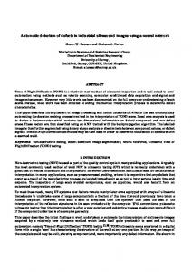
A. Identification of modified local impedance The faulty network shown in figure 1 is first considered. The terminations of the branches are open circuits. It is assumed to be affected by a single defect. The reflectometry response used as the input of GA corresponds to a defect located at 2 m from the input. The change of impedance (due to the defect) is respectively of the order 10%, 20% and 60% of the characteristic impedance of the healthy wire. Figure 2 illustrates the time variation of the signals corresponding to the characteristics of the defects deduced from GA.
1.95
2
2.05
2.1
2.15
2.2
ACKNOWLEDGMENT
2.25
0.2
This work is part of the project SEEDS (Smart Embedded Electronic Diagnosis Systems), in cooperation between Delphi, Serma Ingéniérie, MondiTech, Renault Trucks, CEA-LIST, INRIA, LGEP and supported by the RTRA Digiteo and Région Ile de France.
0
-0.2
Fault Location
-0.4
-0.6
REFERENCES 1
2
3
4
5
6
Distance (meter)
[1]
Fig. 2. Time Domain Reflectometry response B. Reconstruction of a wiring network This second example illustrates the performances of the approach for the reconstruction of a network (location of hard faults). The healthy wiring network of figure 1 is considered. The reflectometry response used as the input is obtained from measurements provided by a vector network analyzer in frequency domain. The parameters of GA are the lengths of the different branches L = [L1, L2… Li] with i is the total number of branch. Figure 3 shows the reconstructed network and Figure 4 compares the reflectometry response of the healthy network (measurements data) and the reconstructed one.
[2]
[3]
[4] [5]
[6]
C. Furse, Y. C. Chung, C. Lo, and P. Pendayala, “A Critical Comparison of Reflectometry Methods for Location of Wiring Faults,” Journal of Smart Structures and System, vol.2, no.1, pp. 25-46, 2006. C. Furse, Y. C. Chung, R. Dangol, M. Nielsen, G. Mabey and R. Woodward, “Frequency Domain Reflectometry for On Board Testing of Aging Aircraft Wiring,” IEEE Transactions on Electromagnetic Compatibility, vol. 45, no. 2, pp. 306-315, May 2003. C. Bucella, M. Feliziani and G. Manzi, “Detection and Localization of Defects in Shielded Cables by Time-Domain Measurements With UWB Pulse Injection and Clean Algorithm Postprocessing, IEEE Transactions on Electromagnetic Compatibility, vol. 46, no.4, pp. 597-605, 2004. C R. Paul, Analysis of Multiconductor Transmission Lines, New York: Wiley, 1994. C. Bucella, M. Feliziani, G. Manzi, “Three-Dimensional FEM Approach to Model Twisted Wire Pair Cables”, IEEE Transactions on Electromagnetic Compatibility, vol. 43, no.4, pp. 1373-1376, 2007. B. Essakhi, J. Benel, F. Duval, G. Akoun, B. Mazari and L. Pichon, “Interconnect Macromodeling from 3D Field Computation, IEEE Transactions on Magnetics, vol.44, no.6, pp. 1454-1457, 2008