Thabit & Abed
Iraqi Journal of Science, 2014, Vol 55, No.2A, pp:444-453
Detection of Subsurface Cavities by Using Pole- Dipole Array (Bristow's Method)/Hit Area-Western Iraq Jassim Muhammad Thabit1*, Ali Mishaal Abed2 1
Department of Geology, College of Science, University of Baghdad. Baghdad, Iraq Department of Applied Geology, College of Science, Anbar University, Ramadi, Iraq
2
Abstract The study area is located within the Hit area, western Iraq. The measurements of Graphical Bristow’s method were carried out by using Pole-dipole array, to delineate the anomaly of apparent resistivity caused by a known cavity target. The survey was applied along two traverses: traverse in W-E direction and traverse in SN direction above Um El-Githoaa cavity. Data interpretation of the traverse trending W-E, with a-spacing equal to(2m)identified the anomaly of the cavity at a depth of (2.6m), (1.6m) height, and( 9.5m) width, while the actual dimensions of depth, height, and width were (3.80m),( 2.2m), and (12.30m) respectively, with variations of depth equal to (1.2m), high (0.8m), and width( 2.8m). The data interpretation with a-spacing of (3m) over the same travers W-E identified small differences from actual dimensions of the cavity, which are approximately equal to (0.4m), (0.6m), and (1m) for depth, height, and width respectively. This means that the survey by using (a=3m) identified a very accurate detection and location of this cave; more than the survey of (a=2m).Therefore, the survey along the traverse S-N is also performed with (a=3m). The data interpretation indicated that the cavity of depth, height, and width are (3.3m),( 2.20m), and(18.6m) respectively, which are approximately the same as the actual dimensions of the cavity with small variations of about (0.5m) depth, (0.4m) high, and (1m) width. It is concluded that the aspacing is a very important factor, because of its effect on the accurate determinations of subsurface cavity. So, it must be taken into consideration in choosing a-spacing in the filed before taking the measurements by using Bristow's method. Keywords: Bristow's method, Pole-dipole array, Electrode spacing-a, Cavities.
( ﻗطﺒﯿن) طرﯿﻘﺔ ﺒرﺴﺘو-اﻟﺴطﺤﯿﺔ ﺒﺎﺴﺘﺨدام ﺘرﺘﯿب ﻗطب-ﺘﺤدﯿد اﻟﻛﻬوف ﺘﺤت ﻓﻲ ﻤﻨطﻘﺔ ﻫﯿت ﻏرب اﻟﻌراق 2
ﻋﻠﻲ ﻤﺸﻌل ﻋﺒد،*1ﺠﺎﺴم ﻤﺤﻤد ﺜﺎﺒت
ﺒﻐداد، ﺠﺎﻤﻌﺔ ﺒﻐداد، ﻛﻠﯿﺔ اﻟﻌﻠوم،ﻗﺴم ﻋﻠم اﻷرض
1
اﻟﻌراق، اﻟرﻤﺎدي، ﺠﺎﻤﻌﺔ اﻷﻨﺒﺎر، ﻛﻠﯿﺔ اﻟﻌﻠوم،ﻗﺴم اﻟﺠﯿوﻟوﺠﯿﺎ اﻟﺘطﺒﯿﻘﯿﺔ
2
:الخالصة
آخذت القياسات بطريقة برستو.تقع منطقة الدراسة في محافظة اآلنبار (منطقة ىيت ) غرب العراق
ﺘوزﻋت اﻟﻘﯿﺎﺴﺎت. وذﻟك ﻟﺘﺤدﯿد اﻟﺸذوذ اﻟﻨﺎﺘﺞ ﻋن ﺘﺄﺜﯿر أﺤد اﻟك ﻫوف، ﺒﺎﻻﻋﺘﻤﺎد ﻋﻠﻰ ﺘرﺘﯿب ﻗطب – ﻗطﺒﯿن -اذ ﻛﺎن أﺤداﻫﻤﺎ ﺒﺎﺘﺠﺎﻩ ﻏرب–ﺸرق واﻷﺨر ﺒﺄﺘﺠﺎة ﺠﻨوب،ﻋﻠﻰ اﻤﺘداد ﻤﺴﺎرﯿن ﻤﺘﻌﺎﻤدﯿن ﻓوق ﻛﻬف أم ﺠذوع أﺴﺘطﺎع،( ﻤﺘرا2) ﺘﺴﺎويa ﺘﻔﺴﯿر اﻟﺒﯿﺎﻨﺎت اﻟﻤﺄﺨوذة ﺒﺄﻤﺘداد اﻟﻤﺴﺎر اﻟﻤﺘﺠﻪ ﻏرب– ﺸرق وﺒﻔﺎﺼﻠﺔ ﻗطﺒﯿﺔ. ﺸﻤﺎل
__________________________
* Email:
[email protected]
444
Thabit & Abed
Iraqi Journal of Science, 2014, Vol 55, No.2A, pp:444-453
ﺒﯿﻨﻤﺎ اﻷﺒﻌﺎد اﻟﺤﻘﯿﻘﯿﺔ.( ﻤﺘرا9.5 )وﻋرﻀﻬﺎ،(ﻤﺘرا1.6) ارﺘﻔﺎع،( ﻤﺘر2.6) ﻤن ﺘﻤﯿﯿز ﺸذوذ اﻟﻔﺠوة ﻋﻠﻰ ﻋﻤق
،(ﻤﺘرا2.2) ،( ﻤﺘرا3.8) واﻟﻌرض ﻛﺎﻨت، اﻻرﺘﻔﺎع، اﻟﻰ اﻟﻔﺠوة أﺴﻔل ﻤﺴﺎر اﻟﻤﺴﺢ ﻤن اﻟﻘﯿﺎﺴﺎت اﻟﺤﻘﻠﯿﺔ ﻟﻠﻌﻤق واﻟﻌرض،( ﻤﺘرا0.8 ) اﻻرﺘﻔﺎع،ﻤﺘرا( اﻟﻰ اﻟﻌﻤق1.2 ) ﻤﻊ وﺠود ﻓرق ﺒﺤدود. ﻤﺘرا( ﻋﻠﻰ اﻟﺘواﻟﻲ12.3)و ( ﻤﺘرا ﻟﻨﻔس اﻟﻤﺴﺎر ﻓﻘد أظﻬرت اﺨﺘﻼف ﻗﻠﯿل ﻋنa=3)أﻤﺎ ﺘﻔﺴﯿر اﻟﻤﻌطﯿﺎت اﻟﻰ اﻟﻔﺎﺼﻠﺔ اﻟﻘطﺒﯿﺔ.(ﻤﺘرا2.8) ،ﻤﺘرا( اﻟﻰ اﻟﻌﻤق1.0 ) و،(ﻤﺘرا0.6 )،(ﻤﺘرا0.4 ) أﻷﺒﻌﺎد اﻟﺤﻘﯿﻘﯿﺔ ﻟﻠﻛﻬف ﻓﻲ اﻟﺤﻘل واﻟﺘﻲ ﺘﺴﺎوي ﺘﻘرﯿﺒﺎ اﻟﻰ متر أستطاع أن ) ا3=a) ﯿﺘﺒﯿن ﻤﻤﺎ ﺘﻘدم أن ﺎﻟﻤﺴﺢ ﺒﺎﺴﺘﻌﻤﺎل اﻟﻔﺎﺼﻠﺔ اﻟﻘطﺒﯿﺔ.واﻟﻌرض ﻋﻠﻰ اﻟﺘواﻟﻲ،أﻷرﺘﻔﺎع
لذلك.متر ) ا2=a) ﯿﺤدد اﻟﻤوﻗﻊ واﻷﺒﻌﺎد اﻟﻬﻨدﺴﯿﺔ ﻟﻛﻬف أم ﺠذوع ﺒدﻗﺔ أﻛﺒر ﻤن اﻟﻤﺴﺢ ﺒﻔﺎﺼﻠﺔ ﻗطﺒﯿﺔ ﺘﺴﺎوي أشارت تفسيرات المعطيات.متر ) ا3=a) شمال بفاصمة قطبية-تم أنجاز المسح بأمتداد المسار المتجو جنوب ( ﻤﺘرا3.3) وﻋرض ﯿﺴﺎوي اﻟﻰ، أرﺘﻔﺎع،اﻟﺤﻘﻠﯿﺔ ﺒﺄﻤﺘداد ﻫذا اﻟﻤﺴﺎر اﻟﻰ وﺠود ﻛﻬف أم ﺠذوع ﻋﻠﻰ ﻋﻤق
وﻫذﻩ اﻟﻨﺘﺎﺌﺞ ﺘﺴﺎوي ﺘﻘرﯿﺒﺎ اﻷﺒﻌﺎد اﻟﺤﻘﯿﻘﯿﺔ اﻟﺤﻘﻠﯿﺔ ﻤﻊ وﺠود ﻓﺎرق.ﻤﺘرا( ﻋﻠﻰ اﻟﺘواﻟﻲ18.6) و،(ﻤﺘرا2.2)، وﻤن اﻟواﻀﺢ أن. ( ﻤﺘرا1.0 ) واﻟﻌرض، ( ﻤﺘرا0.4 ) اﻻرﺘﻔﺎع، ( ﻤﺘر0.5) ﻗﻠﯿل ﻓﻲ اﻟﻌﻤق ﯿﺴﺎوي ﻟذﻟك ﯿﺠب ان ﻨﺄﺨذ، ( اﻟﻤﻨﺎﺴﺒﺔ ﻋﺎﻤل ﻤﻬم ﺠدا ﻓﻲ ﺘﺤدﯿد اﻟﺘﻛﻬف ﺘﺤت اﻟﺴطﺤﻲa ) أﺨﺘﯿﺎراﻟﻔﺎﺼﻠﺔ اﻟﻘطﺒﯿﺔ .ﺒﻨظر اﻻﻋﺘﺒﺎر ﺘﺤدﯿد ﻫذا اﻟﻌﺎﻤل ﻗﺒل أﺠراء اﻟﻤﺴﺢ ﺒطرﯿﻘﺔ ﺒرﺴﺘو
Introduction: Detection and delineation of subsurface cavities and abandoned tunnels using geophysical methods have gained wide interest in the last few decades. The most widely used surface methods include electrical resistivity, electromagnetic, gravimetric, seismic techniques and recently GPR method. Of these methods, the resistivity has been the most extensively used [1, 2, 3, 4, 5, 6]. One of the resistivity techniques is the Bristow's method. There are some researches such as Bristow [5], which applied the Pole-dipole electrode array in a manner which allowed direct graphical interpretation of the cavity targets in approximate depth, position and size. Using this method in field studies, Bristow was able to describe the approximate position of several known passages over karst terrains. Bates [6] used the Bristow's method to delineate a number of known cavities. After making some slight modifications, he was also able to locate a relatively small target cavity. Fountain et al. [7] were able to detect both air-filled and mud-filled cavities. Greenfield [4] located a solution-filled cavity. Ushijima et al. [8] delineated air-filled cavities, all of which are confirmed by drilling. Another researches [9, 10, 11, 12, 13] concluded that the Bristow method is a powerful tool not just for detection, but also for delineation of cavities and it is probably the most sensitive electrical resistivity technique advanced for those purposes. There are few previous studies in Iraq that used resistivity method for detecting cavities; for example Al-Ane [14] used Wenner array to detect the cavities in Hamam Al- Aleel, north Iraq. The resistivity map was drawn which appeared high positive anomalies, where that present of the cavities within gypsum rocks. Al-Gabery [15] collected twelve horizontal profiles, along which resistivity measurements were carried out using Wenner, Schlumberger and Pole-dipole (Bristow’s method) array configurations. It is concluded that the best result was obtained from the Pole-dipole array configuration by using the graphical Bristow method. Another resistivity method is 2D (Two Dimension) imaging surveys, which have been used for shallow engineering and environmental studies, and in following some previous 2D imaging studies are used in detection of subsurface cavities in the world [16, 17, 18].However, 2D imaging has a high cost in comparison with Bristow technique. In the present study, Bristow's method technique is applied in detecting a natural-formed subsurface cavity, which is called Um El-Githoaa with a (3.8m) depth, (2.2m) height, and (12.5m) width within the Fatha Formation in Hit area, western Iraq (Figure 1). Fatha Formation is one of the most aerially widespread and economically important formations in Iraq, which is included in the known cavity studied within the gypsum rock [19]. It comprises anhydrite, gypsum and salt, interbedded with limestone and marl [20], as shown in (Figure 2). The purpose of this study was to evaluate the usefulness and suitability of the Bristow's technique for detecting and imaging the dimensions of these types of subsurface cavities.
445
Thabit & Abed
Figure 1- the location of the Um ElGithoaa cavity (Hit area).
Iraqi Journal of Science, 2014, Vol 55, No.2A, pp:444-453
Figure 2- Stratigraphic succession of the Fatha Formation in Hit area (20).
Traditional Bristow’s Method: An early application of the resistivity method is described by Palmer in 1959 [21], in reference to the location of subterranean caves. This method employed a symmetrical four-electrode configuration in which the half-array electrode spacing ratio was held constant as the array was expanded to provide depth sounding. Bristow modified the pole-dipole electrode array in a manner which allowed direct graphical interpretation of the cavity targets in approximate depth, position, and size [5]. Using this method in the field studies, Bristow was able to describe the approximate position of several known passages over karst terrains. Moreover, he discovered two cavities and verified their existence through boring and excavation. Bates in 1973 applied Bristow’s method to delineate a number of known cavities [6], after making some slight modification; he was also able to locate a relatively small target cavity. The successful results achieved by [6] indicated that Pole-dipole method was potentially applicable to the issue of locating shallow cavities in soil associated with sinkhole formation and underground mud flows in karst terrain. Several field examinations of Bristow’s method have been conducted with various degrees of success by [7, 8, 9, 10, 13, 22]. The Pole-dipole electrode array (Figure 3) incorporates two current and two potential electrodes arranged linearly. One current electrode is placed at an effective infinity, which may be greater than five to ten times the length of distance (P1C1) of the survey line. The two potential electrodes are located at a fixed separation equal of spacing (a). The potential difference is measured between two potential electrodes, by moving current electrode (C1) incrementally with (n=1, 2 ...) for a distance (na) equal approximately to (10a) on either side of the local current electrode (C1), and along the traverse. The measured resistivity profiles will overlap, and the voltage measurements are then expressed as apparent resistivities. These resistivities are indicated by the measured voltage given the relative positions of the electrodes, and assuming the ground has invariant electrical properties throughout [13].Therefore, the apparent resistivity values are plotted against the potential electrode at midpoint position, as shown in( Figure 4) to determine the cavity.
Figure 3- Geometry of the Pole-dipole array for resistivity measurements [13].
446
Thabit & Abed
Iraqi Journal of Science, 2014, Vol 55, No.2A, pp:444-453
Figure 4- Graphic interpretation procedure of Pole-dipole (Bristow's method) resistivity data [13].
On a scale drawing of the vertical section along the survey line, an intersection of two or more equipotential hemispherical shells having radii corresponding to the current to potential electrode separation distance at which resistivity anomalies are observed will locate the subsurface cavity. When this method is applied with sufficient overlap of the resistivity profiles, the subsurface zone of intersection can provide a reasonably good indication of the cavity target, such as cross-section size and depth [23]. Advantage of Bristow's method: With detection of subsurface cavities, there is a good probability that the geological noise may cause mistakes for cavity conditions. To overcome this problem to a useful extent, the interpretation technique devised of [5], and advanced by [6] and [4]; by using high resolution Pole-dipole array is recommended. Its advantage is that the geological noise is greatest near the ground surface, and is spatially distributed, whereas the cavity target is localized. With this technique, overlapping resistivity profiles can be used to separate noise anomalies near the surface from a cavity target at depth. The usefulness of Pole-dipole resistivity profiles is evident in the survey results, no prior knowledge of the target location is required, and both position and depth of cavity along traverse can be derived from the analysis. By demanding that several circular arc intersections, e.g. Three or more, accumulate at an anomaly of subsurface location before declaring it a suspected target, the redundancy of the survey data is used advantageously to enhance the validity of target interpretation [11]. Practical methods are used to analyze anomalies in apparent resistivity caused by the unknown cavity, this method is based upon direct interpretation techniques. Field work: The Um El-Githoaa cavity is located at (N 33° 42-52=, E 42° 48- 55=) about (5Km) to the north of Hit. It is situated in an area surrounded by gypsum within the Fatha Formation. The shape of the cavity is ovulate, the maximum diameter is about (19.3m) at (286° direction), while the minimum is (15.8m) and perpendicular to the maximum. The Bristow’s method (Pole-dipole array) is used to collect apparent resistivity measurements along two traverses, W-E traverse and a perpendicular traverse in S-N direction (Figure 5). The Terrameter SAS (4000) instrument was used for measuring apparent resistivity in the field. The filed layout of Bristow's method: the Current electrodes(C1,C2) of Pole- dipole were planted along the traverse W-E with (50m) separation, and the potential measurements were collected with interval spacing(a) of potential electrodes(P1,P2) equal to (2m), and moving incrementally over intervals of (2m). The multiple current electrode separations were increased to (60m), with potential electrode separation (a= 3m) and horizontal shift of (3m). Current electrodes were laid out along the survey line, and the potential differences at a given location corresponding to each current electrode were measured.
447
Thabit & Abed
Iraqi Journal of Science, 2014, Vol 55, No.2A, pp:444-453
Figure 5-Sketch shows the locations of survey lines.
In the Pole-dipole array (Figure 3) the potential measurement electrodes are relatively close together, the equipotential lines at each electrode contact on the surface may be considered as the edges of curved equipotential surfaces extending below the surface [11].The restricted subsurface region in which an underground anomaly might have influence on the apparent resistivity as determined from the positions of electrodes C1, P1 and P2, as shown in (Figure 4). The survey of the Pole-dipole array by using Bristow's method employs depth sounding profile measurements, in which the potential electrode pair is moved incrementally away from the current source station, first in one direction and then in the opposite direction along the traverse. Then, by moving the current source location along traverse at incremental distances, so that the measured resistivity profiles will overlap the intersection of two or more equipotential hemispherical shells, having radii corresponding to the current–to–potential electrode separation distances, at which resistivity anomalies are observed, which will locate the subsurface cavity. When this method is applied with sufficient overlap of the resistivity profiles, the subsurface zone of intersection can provide a reasonably good indication of the cavity target, such as cross-sectional size and depth. Interpretation: The Pole-dipole apparent resistivity measurements are presented as pseudosection to show lateral and vertical variations of resistivity with depths, as shown in (Figure 6, 8, and 10).The pseudosection is not a true resistivity cross-section, because the vertical scale is not a true depth. However, these pseudosections show anomalous results with high apparent resistivity, which are considered as an indication of weak zones. The actual size and location of these zones can be delineated by the graphical interpretation of the resistivity profiles using the Bristow's method (Figure7, 9, and 11). Figure (6) shows the apparent resistivity pseudosection of the data interpretation of the Pole-dipole measurements (Bristow's method) along traverse W-E, with a-spacing of (2m). It appears increasing in apparent resistivity values near the position of the cave reaching approximately (1410 Ω.m); this may reflect the presence of the cavity near the middle-distance of the traverse line. Another anomaly which is located at the left side of cavity may represent another unknown cavity. The upper part of this section is observed the highest anomalous results of apparent resistivity values, which are caused by the near surface inhomogeneity of dry gypsum rocks.
448
Thabit & Abed
Iraqi Journal of Science, 2014, Vol 55, No.2A, pp:444-453
Figure 6- Apparent resistivity pseudosection along a traverse W-E, with a= 2m.
The upper part of (Figure 7) shows the Maximum residual resistivity anomalies ranging between (500-700 Ω.m).Therefore, they delineate several high apparent resistivity anomalies (H1, H2…), which may be due to the cavity. Graphical interpretation of the Pole-dipole data acquired along the traverse W-E at the lower part of (Figure 7), shows the circular arcs are drawn around each current station at radii corresponding to higher resistance perturbations, than the average apparent resistivity of the host medium, which are represented a shallow gypsum solution of the Um El-Githoaa cavity. The intersecting arcs horizontally aligned a cavity of (2.6m) depth, (9.5m) width, and (1.6m) height, while the actual dimensions of the cavity were (3.80m) depth to the roof, (12.30m) width, and (2.2m) high.
Legend:
Anomaly Location of inside Pole- dipole array. H
Anomaly Location of outside Pole- dipole array. High apparent resistivity anomaly.
Figure 7- Intersecting arcs and interpreted anomaly location for the Bristow's method along a traverse W-E, with a= 2m
Figure (8) shows the apparent resistivity pseudosection of the data interpretation for an overlapping the same Pole-dipole survey line, with (a=3m) of potential electrode spacing. High anomalous results
449
Thabit & Abed
Iraqi Journal of Science, 2014, Vol 55, No.2A, pp:444-453
of apparent resistivity appear in the section, which are surrounded by lower background resistivity; this anomaly is located near the middle-distance of the survey line, and may be reflecting the location of Um El-Githoaa cavity.
Figure 8- Apparent resistivity pseudosection along a traverse W-E, with a= 3m
Figure (9) shows the interpretation of the apparent resistivity data for the same Pole-dipole survey with (a=3m) of potential electrode spacing (a). Maximum residual resistivity anomalies range between (700-800 Ω.m), which may indicate the presence of the Um El-Githoaa cavity, as shown in the upper part of (Figure 9).Meanwhile, the lower part shows the circular arcs intersecting; this determined the location of the cavity. Its depth corresponds accurately to the actual depth of the cavity, except for a small difference of about (0.4m) can be identify, while the width varies about (1.0m) and the height about (0.6m).This means that the survey by Bristow's method of (a=3m) indicates a very accurate detection and location of this cave, more so than the method of (a=2m).
Legend:
Anomaly Location of inside Pole- dipole array. H
Anomaly Location of outside Pole- dipole array. High apparent resistivity anomaly.
Figure 9- Intersecting arcs and interpreted anomaly location for the Bristow's method along a traverse W-E, with a= 3m.
450
Thabit & Abed
Iraqi Journal of Science, 2014, Vol 55, No.2A, pp:444-453
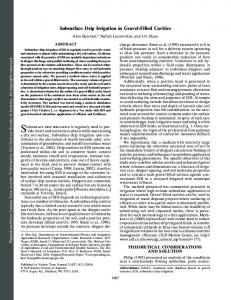
Figure (10) presents the apparent resistivity pseudosection of the data processing of Pole-dipole survey (Bristow's method) along another traverse with) a=3m); this traverse is perpendicular to the first traverse at S-N direction. The high anomalous results of apparent resistivity appear in the section, which are surrounded by lower background resistivity, which may indicate the location of Um ElGithoaa cavity. Also, Figure (10) shows two apparent resistivity responses of Pole-dipole measurements in addition to the cavity anomaly. The first locates at the upper part of section near the Um El-Githoaa cavity, may be caused by surface inhomogeneity of Gypsum rocks. The second is located at the southern part of the section, and may be pointed to unknown cavity. Figure (11) indicates the interpretation of the apparent resistivity data along the S-N traverse with (a=3m). Maximum residual resistivity of cavity anomalies ranged between (570-800 Ω.m) .The lower part of this figure explains the circular arcs that were drawn about each current station at radii corresponding to higher resistance perturbations, than the average apparent resistivity of the host medium. The area of arc intersections determines the location of the cavity with dimensions of depth, width and height ;( 3.3m), (18.6m), and (2.20m) respectively. The dimensions which are achieved from interpretation equal approximately to the actual dimensions of the cavity, with small variations of depth equal to (0.5m), height (0.4m), and width (1.0m).
Figure 10- Apparent resistivity pseudosection along a traverse S-N, with a= 3m
Legend:
Anomaly Location of inside Pole- dipole array. H
Anomaly Location of outside Pole- dipole array. High apparent resistivity anomaly.
Figure 11- Intersecting arcs and interpreted anomaly location for the Bristow's method along a traverse S-N, with a= 3m.
451
Thabit & Abed
Iraqi Journal of Science, 2014, Vol 55, No.2A, pp:444-453
Conclusions: The conclusions of this study can be briefed as follows: 1- Data interpretation of graphical Bristow's method analyses the anomalies in the apparent resistivity, which caused by the Um El-Githoaa cavity (Hit area), along the traverse trending W-E line. It is based upon direct interpretation techniques with potential electrode spacing (a- spacing) of (2m). The anomaly indicated a cavity at a (2.6m )depth, (1.6m) height, and (9.5m ) width, while the actual depth, height, and width are (3.80m),( 2.2m), and (12.30m) respectively, with differences of( 1.2m), (0.8m), and( 2.8m) respectively. 2- Bristow's method with an overlapping along the same traverse W-E above Um El-Gthoaa cavity, with (a=3m) potential electrode spacing (a) is performed. Data interpretation indicated small differences of about (0.4m), (0.6m), and (1.0m) from the actual depth, height, and width of cavity respectively. These differences are less than the differences of (a=2m). 3- Bristow's method along traverse S-N above the Um El-Githoaa cavity with (a= 3m) is applied. The data interpretation indicated that the depth, height, and width of the cavity are (3.3m), (2.20m), and(18.6m) respectively, which are approximately similar to the actual dimensions of the cavity with small variations of depth, height, and width (0.5m), (0.4m), and (1.0m) respectively. 4- The survey by Bristow's method with electrode spacing (a) equal to 3m indicated a more accurate detection and location of Um El-Githoaa cavity, than the method which had a-spacing equal (2m). 5- It is concluded that the (a) spacing is a very important factor, because its effect on the accurate determination of subsurface cavity. So, it must be taken into consideration when using Bristow's method. Acknowledgments The authors are grateful to thank college of science and head of geology department – Baghdad University. We would like to thank dean of College Science and the staff of applied geology department – Anbar University for providing requirements to achieve the field work. Finally we would like to thank my friends, senior geologists (Mohammed M. A. Al Hameedawie, and Ahmed Srdah ALZubedi), and Baraa Y. Hussein for helping us in field work and providing necessary information concerning the studied area and this work. References 1. Cook K. L., and Van Nostrand R. G. 1954. Interpretation of resistivity data over filled sinks. Geophysical Prospecting, 21, pp: 716–723. 2. Vincenz A. 1968. Resistivity investigations of limestone aquifers in Jamaica. Geophysics, 33, pp:980–994. 3. Dutta N., Bose R., and Saikia B. 1970. Detection of solution channels in limestone by electrical resistivity method. Geophysical Prospecting, 18, pp: 405–414. 4. Greenfield R. J. 1979. Review of geophysical approaches to the detection of karst. Bull.Assoc. Eng. Geol., 16, pp: 393–408. 5. Bristow, C. M., 1966. A new graphical resistivity technique for detection of air-filled cavities. Studies in speleology, vol. 7, pp: 204-227. 6. Bates, E. R., 1973. Detection of subsurface cavities. U.S. army engineer waterways experiment station, Misc. Pap. , S-73-40, pp: 63. 7. Fountain, L. S., Herzig, F. X., and Owen, T. E., 1975. Detection of subsurface cavities by surface remote sensing techniques. Federal Highway Admin .Report FHWA-RD-75-80p. 8. Ushijima, K., Mizunaga, H. and Nagahama, S. 1989. Detection of cavities by the misa-a-lamasse and pole-dipole resistivity surveys. Proc. MMIJ/ IMM Symposium, pp: 125-128. 9. Myers, J. O. 1975. Cave location by electrical resistivity measurements, some misconceptions and practical limits of detection, Trans., British Cave Research Association, 2, pp: 167-172. 10. Kirk, K. G., and Werner, E. 1981. Handbook of geophysical cavity-locating techniques with emphasis on electrical resistivity. Federal Highway Admin, Publication FHWA-IP-81-3. 11. Fitch, A. A. 1983. Developments in geophysical exploration methods-5. Applied science publishers LTD, 262p. 12. Lowry, T., and Shive, P. N. 1990. An evaluation of Bristow’s method for the detection of subsurface cavities. Geophysics, 55, pp: 514-520.
452
Thabit & Abed
Iraqi Journal of Science, 2014, Vol 55, No.2A, pp:444-453
13. Elawadi, E., El-Qady, G., Salem, A., and Ushijma.2001. Detection of cavities using pole-dipole resistivity technique. Memoirs of the Faculty of Engineering, Kyushu University, Vol. 61, No. 4, pp: 101-112. 14. Al-Ane, J. M.1993. Detection subsurface cavities by using the electrical resistivity method in Hamam Al-Aleel area. Jour. Geol. Soc. Iraq ,Vol. 26 , No. 1 , pp: 13-26. 15. Al-Gabery, A. S. M. 1997. Geophysical application for engineering purpose-site study. Ph. D. Thesis (Unpublished), in Arabic, Univ. of Baghdad, coll. Of Scie. Iraq, 177p. 16. Zhou, B., Beck, B. F., and Adams, A. L. 2002. Effective electrode array in mapping karst hazards in electrical tomography. Environmental geology, 42, pp: 922-928. 17. Van Schoor M. 2002. Detection of sinkholes using 2D electrical resistivity imaging. Journal of Applied Geophysics 50, pp:393– 399. 18. Roth, M. J. S. and Nyquist, J. E. 2003. Evaluation of multi-electrode earth resistivity testing in Karst. Geotechnical Testing Journal, ASTM, 26, pp:167-178. 19. Jassim, S.Z., and Goff, J. 2006.Geology of Iraq. Dolin, Prague and Moravian Museum, Brno.341p. 20. Al-Ghreri, M. F. T. 2007. Bio stratigraphic succession of the formations in the upper Euphrates valley in the area between Hit and Al-Qaim. PhD. thesis, geology department, college of science, Baghdad University. 189p. 21. Palmer, L. S. 1959. Location of subterranean cavities by geoelectrical methods, The Mineral Mag. (London) 91, pp: 131-147. 22. Greedy, D. P. 1975. Resistivity over caves: Bull. British Cave research Assn., 9, pp: 5-6. 23. 23. Owen, T. E. 1983. Detection and mapping of tunnels and caves: Developments in Geophysical Exploration Methods: A. A. Fitch (ed.), Applied Science Publishers Ltd., Vol.5, pp:161-258.
453