New approach to the detector construction database system design is presented in the paper. The most ... communication problems over WAN (Internet) we decided to apply model ... e.g. connection checking, parsing remote databases' log files, inform ... appliance, which is time-consuming, and maintenance of the resulting ...
Computing in High Energy and Nuclear Physics, 24-28 March 2003, La Jolla, California
Detector Construction Database System for ALICE Experiment W.S. Peryt, T. Traczyk, M. Janik, D. Jarosz, P. Mazan, B. Pawlowski, K. Stanislawek, P. Szarwas, M. Szuba, D. Tukendorf, P. Warecki, J. Wojcieszuk - for ALICE Collaboration Warsaw University of Technology, ul. Koszykowa 75, Warsaw, PL New approach to the detector construction database system design is presented in the paper. The most specific features of applied model are following: (i) distributed (local) databases located at laboratories involved in production, tests and assembly of components and central repository located at CERN. (ii) generic data structures used in design of both local and central databases. (iii) advanced monitoring system with check-in/check-out capabilities for component's flow between labs (iv)making use of generic data structures in user application common for quite different subdetectors (v) using of XML language for data transfers between local databases and the central one.
Specific feature of our approach to the data structure is using so-called “generic structure”. In relational database it means that one set of tables is used for storing data of various structure. It is achieved by designing universal flexible data structures, driven by meta-data (called “dictionaries”). There are two main groups of advantages following from generic structures: (i) concerning flexibility of data structures and (ii) related to application construction. The more detailed description of these topics can be found in further part of this paper. Detector Construction Database System for ALICE consists of several auxiliary subsystems. One of them, Components' Circulation Tracking System, is responsible for keeping order in the Alice databases system by tracing of places where the components currently are, managing components' statuses, managing access rights for components' data etc. Another one, Remote Computer State Analysis System (RCSAS), is responsible for monitoring of remote databases. Its main functions are: performing tests on remote servers, e.g. connection checking, parsing remote databases’ log files, inform administrators about errors found on their servers during tests, e.g. by e-mail, gathering and reporting information on tests’ results. RCSAS has three-layer architecture: database – where it stores all necessary information, main program (splitted into two parts (client and server) and Web application - for data presentation. For security reason connection between server and client is over SSL The system is extensible, that means new tests and actions can be easily added. Essential, from the practical point of view, part of the whole system is communication server (called LabServer), which is a standalone daemon. It allows data exchange between National Instruments LabVIEW and SQL databases.
1. INTRODUCTION ALICE collaboration, which prepares one of the future experiments at LHC/CERN, came into production phase of its detector. ALICE detector consists of many subdectors, designed and manufactured in many laboratories and commercial firms, located mainly in Europe, but also in U.S., India, China and Korea. More than 1000 people and 65 institutions are involved in this enterprise. To assure apropriate environment for this specific task, strictly related to tests of particular components, measurements and assembly procedures, work on Detector Construction Database System started 2 years ago. There are several points which have influnce on design of our system architecture. Many detector components must migrate between manufacturers and laboratories during test and assembly phases. We should be able to trace and register all these movements and synchronize the physical location of components with ownership of related data in database accordingly. The tests/measurements will produce huge amount of data. Practically almost all of them must be stored in database for further analysis and use. Data comes mainly from test benches with software based on LabVIEW suite. The most convenient and reliable solution should assure undisturbed, direct population of database with these data, i.e. without intermediate storage as disk files. Taking into account the above and to avoid potential communication problems over WAN (Internet) we decided to apply model with distributed local (we call them “satellite”) databases located in labs involved in detector production and central repository located ad CERN. The choice of DBMS for Central Database was rather obvious (Oracle) but it wasn't the case for satellite databases. The comprehensive and objective comparison of MySQL, PostgreSQL and Oracle was made to choose DBMS optimally. Communication between satellite databases and the central one is based on the following assumptions: messages are passed in XML, mainly off-line (batch processing), without any satellite-satellite communication. The “requestresponse” model is applied (like in HTTP) and only satellite database can initiate communication.
THKT002
The system as a whole is still under development but several satellite databases already work, central database at CERN is also installed. Further satellite database are in status nascendi.
1
ePrint NONE
Computing in High Energy and Nuclear Physics, 24-28 March 2003, La Jolla, California
generic structure, where Type and Property Definition entities represent metadata, but Object and Property Value entities represent the data describing real objects.
2. DATA STRUCTURES Main assumptions The data collected in satellite databases will be gathered in the central database. It can be done quite easily only if very similar data structures are used for all the satellite databases and the central one. It means, that the data structures for all laboratories, and all detectors and component types should be almost the same. The only way to achieve this in relational database is to use generic data structures. Generic approach makes possible use of one common set of tables for all types of detectors and their components. In generic approach, also a universal “core” application can be created, with possibility to create some more specialized application modules for particular needs.
Typical (specialized) structure versus generic structure Typical specialized (non-generic) structure contains a separate table or set of tables for each type of objects (having different set of properties), and a separate column (attribute) for each property. It means, that if one wants to describe several types of appliances, he should create separate set of tables for each type. In big systems number of tables can be quite high (hundreds), and number of columns can be very high (thousands). Such data structure is complex and very difficult to maintain. It also means, that separate specialized application (containing forms, data browsers, reports, etc.) should be created for each type of appliance, which is time-consuming, and maintenance of the resulting system must be very costly. Figure S.1 shows an example of simple specialized structure.
Type # Id * Name ...
Property value * Value
Property definition # Id * Name * Optional? * Data type ...
Figure 2 Generic structure Advantages In our case, the most important advantage of generic data structures is that the same structure can be used in all satellite databases, and the entire system is therefore much easier to maintain. Structure of the central database can be very similar to the structure of satellite ones, so it is easy to understand the relationships between central and satellite data; no complicated translations between satellite and central structures are required; it is also much easier to introduce changes to both structures. The same generic application can be used on top of all the databases. The application can be dictionary-driven, so it is much easier to maintain. The structure is flexible, so new types of components can be introduced with no need to change the database structure. The structure is also quite simple, it contains about 20 tables, so it is quite easy to understand and to memorize.
Object type A # Id * Property A1 Object type B * Property A2 # Id * Property A3 Object type C * Property B1 ... # Id * Property B2 * Property * Property B3 C1 * Property C2 ... * Property C3 ...
Disadvantages The generic structure is not so straightforward as the specialized one. There may also be more performance problems comparing to not-generic structures (in our case the performance of the generic structure has been tested on large data volumes and proved to be sufficient). The metadata (dictionaries) must be distributed to satellite sites, and changes in the dictionaries should be synchronized in all databases. Procedural constraints (triggers) in the database are necessary to enforce data integrity (e.g. proper typing of values). The generic application is a bit more difficult to create than “normal” one, but we have to create and to maintain
Figure 1 Typical (specialized) structure Generic structure is dictionary-based. It contains the data stored in universal, flexible structures, and metadata (dictionaries), which define the meaning and other features of particular data entries. Metadata contain, for example, dictionaries of object types, properties, etc. In generic approach, one generic set of tables is used for all objects. It means, that the number of tables and columns can be reasonably small, but number of rows in data tables must be definitely greater. Figure S.2 shows an example of basic
THKT002
Object # Id * Name ...
2
ePrint NONE
Computing in High Energy and Nuclear Physics, 24-28 March 2003, La Jolla, California
only one universal application instead of many different specialized applications).
precision of numbers are preserved and scientific notation can be used. The same structure can be used to store a table representing connections between parts of the component. BLOBs (Binary Large Objects) can also be stored in this structure to store binaries: pictures (photographs, etc.) and other binary files. Each process can have several parameters; processes of the same type have identical set of parameters. Data types of these parameters are defined similarly to data types of components’ parameters.
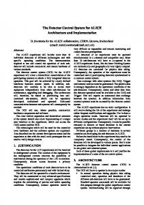
Proposed data structure Proposed generic data structure is shown on Figure S.3. Careful design of primary keys enables the data to be easily integrated into central database (no key conflicts should occur) and the tables and indexes to be easily partitioned. Dictionaries (drawn in gray) are maintained in central repository, supplied from central database to laboratories, and are read-only in satellite databases. Components’ data, created and updated in satellite databases at laboratories are copied to central repository. Components are identified by globally unique internal numerical identifier, user code (locally unique) and a serial number (unique for specific component type). Component state contains properties representing existence (exists, assembled, broken, destroyed), final quality assessment, final acceptation mark, etc. Full history of state changes is recorded Component derivation describes assembling or partitioning of the components, represented by a digraph: nodes represent components, arcs represent composition or derivation (a component may be assembled of other components or derived, e.g. by partition or disassembling, from another one). The location of the component in compound component (e.g. location slot no) can also be recorded. Full history of the assemblage and partition processes is recorded. Components’ parameters Each component can have several parameters. Components of the same type have identical set of parameters but, certainly, values of these parameters may vary. Parameter is identified by a parameter code and a component type code. Values of parameters are stored in text format and can be converted to proper data types as needed, e.g. to calculate an aggregation (sum, average, etc). Data type of each parameter must be defined. Elementary data types are: string, float number, integer number. Derived data types can be defined by enumeration or by restriction of range of allowable values. Each value change is validated against its data type by a database trigger. Full history of changes of component parameters’ values is recorded. Processes are used to store information related to tests, manufacturing processes, measurements etc. Each component can be described by several types of processes, and many instances of each process type (e.g. many repetitions of particular test type). Compound process can include other processes. Complex test results can be stored as series of multidimensional results, represented by a table of n columns: n– 1 coordinates and a test result value. The table is stored in one relational table row, so reasonable query performance is ensured. Object-relational data type (nested table) is used, so each separate data cell can be retrieved using SQL query. Numerical results are stored in text format: scale and
THKT002
Open structure Generic structure features can be used to extend the abilities of the database: new data types, parameters, processes. But the structure should still be refined to reflect new or just discovered needs. The structure itself is extended only if we discover some important data that cannot be stored in current structure in efficient and legible way or we find out that some information is so important and/or common that is should be “honored” by creating separate attribute(s) or new entities for it.
3. MONITORING OF COMPONENTS’ FLOW AND DATA FLOW Purpose Components Flow Monitoring Subsystem is one of the most important parts of the whole System. Its importance comes from the fact that it keeps order in the system as a whole and implements mechanisms that allow avoidance of loosing components during their trips from one testing laboratory to another. The subsystem also provides functionality that helps to maintain consistency of data collected during the test process. Generally the subsystem realizes two main tasks: 1. monitoring of flow of tested components, 2. monitoring of flow of data concerning these components. The following subsection provides detailed descriptions of the tasks.
Monitoring of components The first goal of the Components Flow Monitoring Subsystem is to provide mechanisms allowing components tracking during their travel between laboratories participation in tests. To achieve this, the central inventory of components, which contains actual location, status and history of each component, was introduced. The figure below shows how the monitoring of components is realized in practice. At the beginning each component has to be registered to the system. As registration is usually done in the satellite database, the central inventory has to be notified to make a new component visible to all parts of the system. During registration globally unique identifier for each component is generated.
3
ePrint NONE
Computing in High Energy and Nuclear Physics, 24-28 March 2003, La Jolla, California
Arrival/departure of a component to/from laboratory is also registered in the central inventory. It is performed by checkout/check-in operations provided by the subsystem. Destruction of a component, if occurs, is recorded as well.
Both parts are implemented in java language and communicating each other through the web with use of XML messages. The following figure shows a subsystem’s architecture schema.
Central database
Satellite XML
4. REMOTE COMPUTER MONITORING SYSTEM The goal for Remote Computer Monitoring System} is the ability to check the state of a remote computers from one central place. When we are talking about a state of a remote system what we mean is the availability of miscellaneous resources and network services installed on the host being monitored. RCMS was developed because of the need to monitor the state of satellite database systems, those storing information about current production state of ALICE detector parts (the whole production system consists of one central database and number of satellite database systems).
Encountered problems and their solutions Unfortunately the basic model described in the previous subsections doesn’t cover all requirements. The list of required features that had to be added comprises: 1. enforcing users to enter proper location of a particular component, 2. possibility of data transfer from satellite database to some auxiliary database (e.g. on notebook), 3. delays prevention in case of long-lasting abnormal conditions like communication failures. As a solution for the first problem dependence between component and data check-in/check-out operations was introduced. In a typical situation a particular satellite database can check-out data of a given component only if it checked-out the component itself before. To provide the second feature, special authorization mechanism was introduced. A satellite database that has the component itself can pass write access to its data to other satellite database. To avoid delays in the test process in case of abnormal conditions the subsystem provides special mode which allows modification of data in satellite database even if there is no possibility to check it out from the central database.
Architecture RCMS is build using three tier application model. In RCMS those three tiers includes: presentation tier - in particular this is a web interface to view, find, filter etc. data in data base (test results). This part is made using JSP pages and servlets. business logic tier - the heart of every application. In RCMS this part includes test invoker, test runner, tests and actions. All these parts are described later. data management tier - database which stores information about monitored hosts and user privileges (users of web applications - administrators of monitored hosts). Particularly interesting is the middle, business logic part of the RCM S system and that is why it will be explained in more detail in this paper. The whole system is written in Java programming language thus it is very portable among operating systems. Heart of RCMS system (the part which actually performs monitoring) consis ts of following: Tests Services and resources of a remote host being monitored are checked during tests. Single test is actually a single Java class with a method runTest() which performs a test. There are two major types of tests. First group includes test which do not require an account on monitored system this includes e.g. ping tests. Second group includes tests like the one which checks free space on a hard drive, so the tests which require an local account on the system being monitored. Tests in different groups are differently invoked. New tests can be added simply by writing new Java test
Implementation The architecture of the Components Flow Monitoring Subsystem has to be compliant with the architecture of the system as a whole. For that reason the subsystem consists of two parts: 1. central – co-working with the central inventory, 2. satellite – co-working with a particular satellite database.
THKT002
Central servlet
This part of the Components Flow Monitoring Subsystem is responsible for a distribution of a write access to the components’ data collected during tests. It ensures that in “normal” circumstances only one satellite database can modify data of the particular component at the same time. It also guarantees that version of component’s data that is updated in the given laboratory is always up-to-date. As in case of the components’ monitoring, used solution is based on a central inventory which contains such information like name of the database that has write access to data of the particular component and number of a current version of a data. Operations provided by the subsystem in the context of monitoring of data flow are also similar to those used to monitor components’ flow. If a particular laboratory wants to have write access to component’s data it should check-out it from the central database. When modifications are completed, data should be checked-in back.
Satellite databases
XML
Monitoring of data flow
4
ePrint NONE
Computing in High Energy and Nuclear Physics, 24-28 March 2003, La Jolla, California
class. Which test to run are defined on a host basis so for a different host we can have different test sets to run. Actions After a test finishes an result is returned. For each result returned test invoker triggers actions. Action can actually be any thing. Action can store result to database or send SMS or e-mail message to administrator of an monitored server about some kind of an error which occurred during a test. Which actions to run are defined on a host basis so for a different host we can have different action sets to trigger. Because action is actually a Java class new actions can be easily added just by creating new Java class. Test Invoker Invoker is responsible for running test. It reads data form database (data about test, actions and monitored hosts) and performs test and triggers actions when a test finishes. Test invoker should be installed only on one system (the monitoring system). It can run a test by it self only for the first group of tests (those which do not require account on a monitored computer). For the second type of test it uses test runner. Test Runner Test runner should be installed on every monitored system. It receives tests (instances of a test classes) from test invoker, runs a test on it's behalf and returns result back to the test invoker.
use the same classes on invoker and runner sides so there is no threat of test invoker and test runner having different versions of the same test class. As s aid before both test runner and invoker have it's separate configuration files which allow to customize their runtime behavior. No data is sent unencrypted. New test and actions can be added to support more functionality. Because of it's flexibility Remote Computer Monitoring System can be very powerful tool for system administrators to help them diagnose and inform about problems on system their administer.
5. LabsServer Populating the databases with acquired data provides an interesting challenge of designing a generic and robust interface between the LabVIEW application and the RDBMS, as LabVIEW itself doesn't offer such a possibility. We have designed a separate tool for this purpose: LabServer. LabServer is a standalone program written in POSIXcompliant C, designed to operate as a networking daemon – ie. to remain in the background, waiting for incoming client connections. As one is accepted, the daemon spawns a separate instance of itself which then processes the requests, allowing its primary one to carry on listening – thus being able to handle concurrently as many client connections as configured for.
All of these parts can be configured using configuration files which consists of an key, value pairs. Those parameters are used to customize test, actions, test invoker and test runner. How it works Figure shows simplified view of how the whole RCMS system works. When the test invoker starts it reads its configuration file and then connects to the database to check which tests should be run and which host to monitor. After getting this information it starts separate thread for each test it invokes. Maximum number of simultaneous threads can be limited by appropriate variable in configuration file. In each thread a test is invoked, that is for each test appropriate Java class is downloaded from the network (you describe where action and test classes are located as a runtime parameter). Then, when a test belongs to the first group of tests, invoker performs it otherwise, when test belongs to a second group of tests, invoker connects to test runner on monitored system, authenticates it self using username and password (these two are configured per host basis) and send test object to the remote host. The connection between test invoker and test runner is encrypted so neither passwords, test and results are sent unencrypted. When test runner receives a test it first downloads test class from the same place as the test invoker did and after performing test returns test result to the test invoker over this secure SSL connection. After receiving test result (no mater of what kind of test) test invoker triggers appropriate actions and after this it destroys thread of this test invocation. While the test invocation threads are running test invoker in, it's ma in loop, waits (using sleep} system function) for the next tests run cycle. When defining test for a particular host one has to also define time interval between subsequent test invocations for test being defined so the system knows how long can it sleep before the next test invocation cycle. Dynamic tests and actions class loading give the ability to
THKT002
Such a solution has got several advantages over implementing such functionality into the LabVIEW application. First of all, keeping the database access separate allows using the same data source with different database systems – the two currently supported are MySQL and PostgreSQL, with plans for Oracle support in the future; the application-daemon protocol doesn't have to change. Second, different components of the setup can run on different machines, each of them suited for its purpose. Last but not least, unlike LabVIEW, LAbServer and all the libraries it co-operates with are Open Source. There are two ways in which LabServer can operate. In raw mode, the daemon directly transmits SQL queries and their results between the application and the database. In parsed mode, the daemon accepts input data in the predefined format, converts them to a sequence of SQL queries and fills the tables accordingly. There are currently two branches of LabServer available. The older one, versioned as 1.0.x, contains the original raw mode code as well as a custom parser/formatter designed to work with version 1.13 of the database structure; it is known to be stable. The newer one, to be versioned as 1.1.x but marked 1.0.9x at present, has undergone a complete rewrite of the parsed mode code in order to reflect the changes in both the input format (valid XML) and the database structure (1.23c); it has already been confirmed operational, but awaits testing in production environment.
5
ePrint NONE
Computing in High Energy and Nuclear Physics, 24-28 March 2003, La Jolla, California
Due to its modular design, the core of LabServer itself is independent of any libraries other than the standard C one. The modules requiring additional software are: • MySQL and PostgreSQL support – their client API libraries (libmysqlclient and libpq respectively); • host-based access control – the popular TCP Wrappers suite (libwrap); • the new-style parser – GNOME XML library version 2 (libxml2).
and distinct. Presentation layer is made by means of Java Server Pages technology (JSP). JSPs live withing Web server and can create pages differently based on velues returned from business layer. Business layer is Jakarta Tomcat servlet container with servlets. Servlets are responsible for managing data stored in database. Database tier consists of PostresSQL or Oracle database. To fullfil all this requirements developers have decided to use Model-View-Controller (MVC) design pattern. MVC is a way of decomposing an application into three parts: the model, the view and the controller. Controller – is responsible for intercepting and translating user input into actions to be performed by the model, this is servlet which gathers all request derived from clients, for example: register new component. Model – represents an application’s data and contains the logic for accessing and manipulating that data. Any data, that are part of the persistent state of application reside in the model objects. The services that a model exposes seems to be generic enough to support a variety of clients. View – is responsible for rendering the state of the model. View forwards user input to the controller. Model consist of pure Java classes and uses Data Access Objects (DAO) design pattern to encapsulate access to data stored in database. Moreover DAO allows for cross-database and cross-schema portability. These Java classes expose abstract methods for accessing and updating the state of the model and for executing complex processes encapsulated inside the model. By glancing at DAO’s public method list, it should be easy to understand how to control model’s behavior, for example public Collection getDefinedComponents(String detectorCode). This application seems to be well designed and we are able to switch to EJB, but now we do not do that, because EJB is probably to complex as far as this application is concerned. To build this application Struts framework was used. Struts is one of the Apache projects and this is a framework for building Java based web applications. More information about Struts are available at http://jakarta.apache.org/struts . Sometimes there is a requirements to presents component’s or processes data as graphical images. In order to do it Root and Carrot is used. Root is an objectoriented framework aimed at solving the data analysis challenges of high-energy physics. Images are produced by means of root. Carrot is module for Apache web browser, and allows to present graphical images produced by root directly in web browser. For more information about root and carrot refer to http://root.cern.ch and http://carrot.cern.ch respectively.
6. User application User application for construction database. User application is one of the most important thing, which has to be created. This part of the whole system allows end users to work with data stored in databases, satellite database as well as central database. In order to prepare high quality product, building process will be based on RUP (Rational Unified Process) and by means of Unified Modeling Language (UML). UML is de facto standard methodology for ilustrating and modeling software engineering concepts in an unambiguous way. UML is a highly imp ortant achievement is object-oriented methodology and this is a common mechanism for developers to communicate and design. RUP provides a detailed processes, activities, and tasks to be undertaken by team members is clearly defined roles. First of all system disigners had to collect user requirements. Without this, it can be situation, when nobody will want to use the final product. End users help developers with discovering real requirements for application. The main requirements are: application should be accessible through web browser. This is also knows as “thinclient” and is quite challenging endeavor. A thin-client application is one in which ther server side is responsible for generating the user interface into the application. This product should be able to work with different database management systems. In this case there will be: PostgreSQL as satellite database (i. e. in Nanates, or Strasbourg) and Oracle as sattelite database (Darmstadt) and as central database (CERN). Next requirements was that, it must be easy way to separete “model layer” and presentation layer. One of the main requirements, maybe not for users, but surely for developers, is that, developers should be able to add new module as easy as possible. For example, data exchene module and “check-in, check-out” module will be integrated with this user interface. This application will be created for a long time, and developers should be able to remove and add new functionality. Application architecture is very important issue. After discussion tree tier architecture was chosen. This tree tier architecture consists of: presentation tier, business tier and database tier. Each layer is completely independent
THKT002
6
ePrint NONE
Computing in High Energy and Nuclear Physics, 24-28 March 2003, La Jolla, California
DEFINITION OF PARAMETER of type
# * o o o *
PARAMETER CODE NAME SEQUENTIAL NO UNITS OF MEASURE DESCRIPTION IS ACTIVE
DETECTOR
# DETECTOR CODE * NAME o DESCRIPTION o CATEGORY
group of
defines
PARAMETER
defined by # V A L I D F R O M o VALID TO o VALUE
of type
in group
MANUFACTURER
delivers
# TYPE CODE * NAME * IS ACTIVE o DESCRIPTION
source of
described by includes of type
s o u r c e o f derivative
derivative
processed by
of type
in process .
consists of
DATA TYPE
# DATA TYPE CODE * NAME * ELEMENTARY TYPE o DESCRIPTION
belongs to
belongs to
DEFINITION OF PROCESS # * * o o o *
PROCESS CODE NAME PROCESS TYPE SEQUENTIAL NO DESCRIPTION VT MAX ROWS IS ACTIVE
consists of defines defined by
c o n s i s t s o hf a s p a r a m e t e r s
manufactured by
in group
coded by
includes
delivered by
COMPONENT # o o o * * o
COMPONENT ID USER CODE SERIAL NUMBER DESCRIPTION IS SKELETON IS VIRTUAL PRODUCTION DATE
processed by
PROCESS
# PROCESS DATE o DESCRIPTION o VALUE TABLE o PROCESSED BY o INSPECTED BY * IS VALID * IS SKELETON
.
DEFINITION OF VT COLUMN value type
.
constrained by of type
.
# o o o o *
COLUMN NO COLUMN TYPE LABEL UNITS OF MEASURE DESCRIPTION IS ACTIVE
in process
DEFINITION OF PROCESS PARAMETER # * * o o o *
PARAMETER CODE NAME PARAMETER TYPE SEQUENTIAL NO UNITS OF MEASURE DESCRIPTION IS ACTIVE
described by
defines
derivative
in
derivative
COMPONENT DERIVATION
consists of
# o * o o o
VALID FROM VALID TO DERIVATION TYPE SECTOR NO POSITION NO DESCRIPTION
has
describes
COMPONENT STATE
of test .
BLOB
as VT column # * o o o of o o
ALLOWABLE VALUE
source of source of
for
for
# SEQUENTIAL NO * VALUE o HIGH VALUE o MEANING o NUMERICAL VALUE
consists of
creates code
COMPONENT TYPE belongs to
belongs to
COMPONENT GROUP
described by belongs to
* DERIVATION TYPE o DESCRIPTION o QUANTITY o MAX SECTOR NO o MAX POSITION NO
DATA BASE
of
includes
consists of
COMPONENT TYPE DERIVATION
site
# MANUFACTURER CODE # DATABASE CODE # GROUP CODE located in * NAME * NAME * NAME * IS LAB o DESCRIPTION creates o DESCRIPTION
NO BLOB VALUE BLOB DATE FILE NAME FILE PATH FILE OWNER DESCRIPTION
# o * * o o o o
VALID FROM VALID TO EXISTENCE COMPLETE QUALITY ACCEPTED LOCATION DESCRIPTION
PROCESS PARAMETER defined by
o o
VALUE DESCRIPTION
Figure 3. Data structure for satellite database
THKT002
7
ePrint NONE