Determining the Area Function of Spherical Indenters for Nanoindentation. Andrew J.Bushby. 1 and Nigel M. Jennett. 2. 1. Department of Materials, Queen Mary, ...
Author’s preprint of MRS Symp Proc 649 (2001) Q7.17.1
Determining the Area Function of Spherical Indenters for Nanoindentation. Andrew J.Bushby1 and Nigel M. Jennett2 1 Department of Materials, Queen Mary, University of London, UNITED KINGDOM 2 NPL Materials Centre, National Physical Laboratory, Teddington, UNITED KINGDOM. ABSTRACT Nanoindentation with spherical tipped indenters provides a powerful technique for exploring surface mechanical properties through the application of Hertzian mechanics. The full range of mechanical response can be obtained from elastic, through the yield point to a range of permanent deformation. However, the successful application of the technique requires accurate calibration of the indenter tip geometry. In this paper methods based on indentation into a number of reference materials are used to characterise a range of spherical tipped indenters with nominal radii from 5 to 50 microns. A traceably calibrated metrological AFM is also used to determine the actual shape of one of the indenters. The sensitivity of each method to test parameters is discussed. Coincidence of the data from both methods validates the determined shape of the indenter and offers the opportunity to cross-correlate the calibration of both instruments with high sensitivity. INTRODUCTION Spherical indenters are a useful weapon in the armoury of nanoindentation. They allow the determination of a wide range of mechanical behaviour and can provide complementary information to experiments with pointed indenters (pyramids and cones)[1]. Specifically they can provide: material responses exclusively in the elastic regime for both bulk and thin film materials[2]; yield behaviour, in the form of the elastic limit[3]; indentation stress-strain curves can be generated, using appropriate techniques[4]; data for comparison with axisymetric numerical models; and, the geometry can be used for certain critical instrument calibration issues such as the determination of instrument frame compliance. The successful application of spherical nanoindentation techniques requires accurate calibration of the indenter tip geometry. In nanoindentation diamond indenters tend to be used for their high hardness and elastic modulus. However, the indenters often deviate from an ideal spherical shape due to the difficulty of polishing an anisotropic crystal into a spherical shape. Calculation of the effective shape, or area function, for pointed indenters is often based on indentation into reference materials[5]. Methods using two reference materials have shown good agreement with direct imaging using atomic force microscope (AFM) techniques[6]. In this paper we discuss similar methods for calibrating the effective radius of spherical indenters, Reff, by indentation into reference materials with known properties using Hertzian contact mechanics and by directly imaging the indenter on a traceably calibrated metrological atomic force microscope (AFM). DEPTH SENSING INDENTATION (DSI) METHOD For elastic contact between a sphere and a planar surface, the total elastic displacement, he, from Hertzian contact mechanics, as given by Johnson[7], is:
Author’s preprint of MRS Symp Proc 649 (2001) Q7.17.1
1/ 3
9 F he * 16 E
2/3
1 R
1/ 3
(1)
where F is the applied force, R is the radius of the sphere and E* is the composite modulus of the sphere and the planar surface given by
1 s 1 i 1 * Es Ei E 2
2
(2)
where E is Young’s modulus, is Poisson’s ratio and subscripts s and i refer to the surface and indenter respectively. In reality, we measure in the laboratory 9 he hm ho C f F 16
1/ 3
F E *
2/3
1 R eff
1/ 3
(3)
where hm is the measured penetration, ho is the penetration correction associated with contacting the surface, Cf is the instrument frame compliance, Reff is the effective indenter radius and is a function of the depth of the sphere in contact with the surface, hc. The effective indenter radius can be obtained by indenting into reference materials with known elastic properties and rearranging equation 3 to give Reff in terms of the measured quantities F and hm. Input values for the elastic properties of the indenter and the instrument frame compliance, Cf, are also required. Ideally, the reference materials should be homogeneous, isotropic and with a perfectly flat surface, free from artefacts (eg. surface damage due to polishing). It is important to validate the values for Cf , E* and the function Reff (hc) by indenting into a number of reference materials spanning a wide range of elastic moduli. Superposition of the curves, as in Figure 1, can only be achieved if all the input parameters have been accurately determined. 50
Effective Radius / m
45
Table I. Elastic constants of reference materials.
40 35 30 25
FS
20
InP
15
CrC
10 5 0 0
100
200 300 400 Depth Below Contact / nm
Figure 1. Reff vs hc for purely elastic indentation into reference materials, Rnom = 50m, Cf = 0.24nm/mN.
500
Material Fused Silica BK7 glass InP (single crystal) Fe (single crystal) Cr 1%C W (single crystal) Diamond
E / GPa 72 85 95 210 335 410 1150
0.17 0.21 0.26 0.28 0.22 0.29 0.07
Author’s preprint of MRS Symp Proc 649 (2001) Q7.17.1
For small radius indenters (R < 10m) the range of depth over which indentation in the elastic regime can be maintained is limited by the reference material with lowest ratio of elastic modulus to hardness (typically glass or fused silica). To extend the range of calibration into the elastic-plastic regime, it is necessary to consider the elastic unloading of the elastic-plastic indentation. In this case the Equation (1) becomes 9 he 16
1/ 3
F * E
2/3
1 1 R R'
1/ 3
(4)
1 1 where is the relative curvature between the sphere and residual impression. R R' a 2 hr2 R' and (5) 2hr where hr is the depth of the residual impression and a is the radius of the circle of contact under load given by
a 2 2Rhc hc2
(6)
For non ideal indenters an effective radius, Reff(hc), may be assigned in a similar manner to the elastic case. Rearranging equation 4 and substituting equations 5 and 6 gives a quadratic in terms of hc and hr, the positive root of which is Reff. Reff can be obtained as a function of hc by using the partial-unloading routine of Field and Swain[4]. As with the elastic case, it is necessary to validate Cf , E* and the function Reff(hc) by indenting into a number of reference materials spanning a wide range of elastic moduli. Again, superposition of the curves, as in Figure 2, can only be achieved if all the input parameters have been accurately determined. 5 Effective Radius / m
Effective Radius / m
14 12 10 8 FS FS Elastic BK7 Fe W AFM data
6 4 2 0 0
100
200
300
400
500
600
Depth below contact / nm
Figure 2a. Reff vs hc for elastic-plastic indentation into reference materials, Rnom = 10m, Cf = 0.24nm/mN.
4.5 4 3.5 3 2.5 W InP FS
2 1.5 1 0.5 0
700
0
100
200
300
400
Depth below contact / nm
Figure 2b. Reff vs hc for elastic-plastic indentation into reference materials, Rnom = 5m, Cf = 0.24nm/mN.
The indentation test method is susceptible to thermal drift and to measurement uncertainties in F and h. The resulting Reff vs h relation is particularly sensitive to uncertainties
Author’s preprint of MRS Symp Proc 649 (2001) Q7.17.1
in h since R 1/h3. Also, the two surfaces in contact both have a non zero surface roughness. The method is limited at low h by the interaction of roughness asperities and deviation from ideal elastic behaviour, e.g. due to the presence of oxide films, porosity or absorbed layers. In general, hard materials with a low surface roughness (e.g. glasses and semiconductor materials) will give more accurate representations of Reff at low h. In this range the coincidence of the curves for different materials is dictated by the value of E* and is relatively insensitive to Cf. At high h the method is limited for ductile materials by the effects of pile-up or sink-in and, for brittle materials, by cracking. All of these effects may change the apparent stiffness of the system. At high h the coincidence is very sensitive to Cf, and may be used to determine Cf to within 2%. This result is independent of any calibration error in h. ATOMIC FORCE MICROSCOPE (AFM) MEASUREMENTS
Effective Radius / m
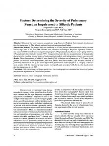
Indenter tips were imaged with a traceably calibrated metrological AFM to determine the actual shape of the 10m radius indenter. The X, Y and Z axes of the AFM were calibrated using an etched Si sawtooth artefact that had been traceably calibrated for sawtooth period and sawtooth angle sum. Traceability was derived from a HeNe laser, Jamin interferometer. The method and calibration of the metrological AFM used has been thoroughly described elsewhere [8, 9]. The AFM probe radius was estimated by scanning the corners of cubic TiN crystals, which had been deposited onto steel by PVD. Images of the corners of these crystals consist of the locus of the crystal and the AFM tip. The radius of the smallest features in an image provides a ‘worst case’ estimate of the AFM probe radius and yielded radii in the range 9-20nm. The indenter tips were scanned in the X direction and in the Y direction with a scan size of 7.7m. The scans were repeated at a scan size of 3.9m to increase pixel resolution. The indenter was then rotated through 90 and the complete X and Y scan sequence repeated. 14 12 10 8
0 X 7.8um 90 X 7.7um 90 X 3.9um 90 Y 7.7um 90 Y 3.9um
6 4 2 0 0
200
400
600
800
Distance from tip / nm
Figure 3. AFM data presented as a contour plot giving an impression of the overall shape and sphericity of the indenter. 80 equally spaced contours at 28nm height intervals.
Figure 4. Reff vs h from AFM data for various scan and sample rotations.
Both mechanical and thermal drift can be experienced during the time of a scan (512s). The lateral drift of the AFM image was estimated to be below 1% by tracking the movement of
Author’s preprint of MRS Symp Proc 649 (2001) Q7.17.1
features on the image over time. The Z detector had a bit-noise limited signal resolution of 0.44nm. Rotating the sample between two sets of scans and changing the scan direction can show when these effects have been minimised by reproduction of the same shape. This is easier to see for pyramidal indenters but is more difficult to recognise with a spherical indenter. Drift in the Z axis is particularly difficult to detect as this causes a tilt in the image rather than a distortion to the symmetry. Reproducibility of images from different scan directions and sample positions was used to indicate that the final data taken was not significantly affected by drift or other scan induced artefacts in the images. The AFM image is a good indication of the sphericity of the tip, Figure 3. The cross sectional area, A, of the image at a series of height steps from the apex, h, was calculated using a pixel counting algorithm. This was then converted to Reff vs h (Figure 4) using Equation 6, so that A = a2 = (2hReff - h2)
(7)
DISCUSSION
Effective Radius / m
Hertzian mechanics links the unloaded geometry of the indenter to the loaded contact area. AFM directly measures the unloaded shape. Therefore, the derived functions of Reff from each method should be coincident. In practice, the zero of the two displacement scales may not coincide. Both methods are subject to uncertainties and sources of error. In the indentation test, contact is often defined as that between the solid surfaces and does not include the asperity or any surface layer effects, e.g. capillary water layers, hydrated layers etc. In the AFM measurement, the zero in h is the highest point in the scan and corresponds to the extreme of the combination of shape, vibration, other noise and roughness asperities. These two reference points are therefore not the same and it is necessary to translate the AFM data by a few nanometres in h to obtain the same reference datum and hence agreement between the two data sets. AFM surface roughness measurements of the indenter indicated that translations of at least 2nm would be required. An objective criterion for translation of the AFM data is required. The initial values of Reff are extremely sensitive to translation of the h scale. Often, Reff will switch from an initial steep increase in Reff (from near zero) to a steep decrease (from near infinity). Translation of the h scale to obtain initial Reff values at the transition between these extremes, corresponds to eliminating the effect of asperities in the shape of the indenter and is therefore equivalent to the surface contact definition often applied to the indentation data. This procedure has been adopted in the AFM data presented in Figure 2 12 and Figure 4. 10 8 6
Figure 5. A 5% change in the depth calibration of the indentation system results in a vertical translation of the Reff vs h function (- - - )
4 2 0 0
100
200
300
400
500
Depth below contact / nm
600
700
Author’s preprint of MRS Symp Proc 649 (2001) Q7.17.1
A systematic difference in the depth calibration of either instrument gives rise to a vertical translation of the Reff vs h relation, Figure 5. Coincidence of the curves from both methods validates the determined shape of the indenter and offers the opportunity to crosscorrelate the calibration of both instruments.
CONCLUSIONS 1. Traceable calibration of diamond indenters by metrological AFM provides an independent calibration input to the indentation process and is therefore highly recommended. 2. Given the third power relationship of h in the Hertz equation, a reliable independent measurement of indenter area function and reference sample modulus enables a very sensitive indirect calibration of DSI instrument displacement and can be more sensitive than some commonly used, traceable, direct calibration methods. 3. Self consistency in the Hertz based spherical indentation method allows accurate determination of frame compliance by indentation into multiple reference materials. 4. The ability to exactly match the form of AFM and indentation derived radius functions indicates that the use of an effective radius in the Hertz equation is a valid method to describe both elastic and elastic-plastic indentation contact.
REFERENCES 1. B.R.Lawn , J. Am. Ceram. Soc., 81, 1977-1994, (1998) 2. A.J.Bushby, “Nano-Indentation Using Spherical Indenters”, accepted for publication in Nondest. Test. and Eval., 2000. 3. A.J.Bushby, et al “ Physical Origin of a Size Effect in Nanoindentation” this volume. 4. J.S.Field and M.V.Swain, J. Mater. Res., 8, 297-306. (1993) 5. W.C.Oliver and G.M.Pharr, J. Mater. Res., 7, 1564-1583, (1992) 6. K. Herrmann and N.M.Jennett et al “Progress in determination of area function of indenters used for nanoindentation” Proc ICMCTF2000, San Diego (to be published in Thin Solid Films) 7. K.L.Johnson, “Contact Mechanics”, Cambridge University Press, (1985) 8. N M Jennett; G Shafirstein; S R J Saunders. in Hardness Testing in Theory and Practice Proc. 9th Int. Symp. Hardness Testing in Theory and Practice, Düsseldorf, Nov 1995 VDI Berichte, 1194 pp201-210 Publ. VDI-Verlag GmbH, Dusseldorf, (1995) 9. Nigel M Jennett and Jan Meneve; Mat Res Soc. Symp Proc. 522, 239-244, (1998) ACKNOWLEDGEMENTS The authors would like to acknowledge the financial support of the European Commission under Contracts MAT1-CT94005 ‘FASTE’ and SMT4-CT98-2249 ‘INDICOAT’ and of the UK Government Department of Trade and Industry.