We study event processing in locally distributed real- time systems. The objective is to use event-triggered communication together with a time-synchronization.
2007 International IEEE Symposium on Precision Clock Synchronization (ISPCS) for Measurement, Control and Communication Vienna, Austria, October1-3, 2007.
Determinism in Event-Triggered Distributed Systems with Time Synchronization*
Edward A. Lee, Slobodan Matic Electrical Engineering and Computer Sciences University of California, Berkeley {eal, matic}@eecs.berkeley.edu
Abstract We study event processing in locally distributed realtime systems. The objective is to use event-triggered communication together with a time-synchronization protocol, in particular, IEEE 1588 over Ethernet, to achieve the similar level of determinism as in statically scheduled time-triggered systems. Given a distributed application with component properties and input event rate characterization, we discuss an analytic procedure that bounds performance parameters. These parameters are also necessary for deterministic implementation of the application. The procedure is experimentally evaluated on a setup with standard software and networking components.
1. Introduction One of the main problems in the design of networked systems of embedded computers that control physical processes is to map a desired behavior on a distributed computing platform under given physical constraints. The typical constraints bound the time needed for computation and communication over shared resources. The deterministic and timely response is often required to achieve fault-tolerance. For instance, replica determinism demands the redundant nodes to take the same decision at about the same time. Most software architectures and communication protocols used in deterministic real-time systems are time-triggered, i.e., all actions are initiated by temporal events that follow a global statically computed schedule. The time-triggered approach is preferred for its compositionality, because component integration does not introduce new performance dependencies. However, *This work was supported in part by the Center for Hybrid and Embedded Software Systems (CHESS) at UC Berkeley, which receives support from the National Science Foundation (NSF award #CCR0225610), the State of California Micro Program, and the following companies: Agilent, Bosch, DGIST, General Motors, Hewlett Packard, Infineon, Microsoft, National Instruments, and Toyota.
it becomes inefficient with increasing system complexity, especially if the network traffic is irregular. On the other hand, event-triggered approach, where a communication action can be started by a non-temporal event, is preferred for flexibility and, often, implementation simplicity. In this paper, we concentrate on the eventtriggered approach, where the schedule unfolds dynamically during runtime, depending on the occurrences of different events. We focus on the Ethernet as the underlying network, although the definitions and analytic procedures can be applied to other local networks. In recent years, there were several successful approaches in industry to replace different field-bus and information networks with the Ethernet [1]. This technology has considerably evolved to reduce and eliminate collisions by introducing switched Ethernet solutions and dual duplex links. The application-to-application delays on small networks were reported to be less than a millisecond even with link utilization above 95%. However, real-time behavior and determinism are still a concern, since Ethernet in its basic form is event-triggered and asynchronous with respect to network access. Therefore, most solutions either enhance the switch architecture or adapt the node network driver. Some of the relevant techniques include PROFINET [2] (time-slotting), EtheReal [3] (enhanced switch scheduling), Powerlink [4] (master-slave), and TTEthernet [5] (time-triggered switch). Within the context of time-triggered systems Kopetz [6] defines timely and deterministic transmission channel with the following three properties: 1) the message delay is bounded and the bounds are a priori known, 2) the receive order of messages is the same as the send order, and 3) the receive order of messages sent simultaneously is a priori known. In this work, we study similar requirements for timely and deterministic input-output behavior of event-triggered distributed systems. Here the requirements address timing and order of event processing only, and allow for more flexibility in the event communication order. The future cyber-physical systems will consist of hundreds of information processing components and the
global control of the information traffic will be unlikely to succeed. In this study, the common global time will be used to process the events locally, but not to control the access to the network in the static manner. Our experimental setup consists of nodes containing clocks synchronized using the IEEE 1588 protocol. By using node and network resources only minimally, this synchronization protocol achieves the common notion of time with tens of nanoseconds precision. In addition, a real-time operating system is needed to achieve software preemption and interrupt latencies in the order of tens of microseconds. The estimation of upper bounds of synchronization and other event processing latencies is important not only for performance, but also to enforce deterministic behavior, since the event scheduler decisions depend on these bounds. One of the objectives of the paper is to study pros and cons of real-time deterministic event-triggered systems built on open source software, standardized protocols and off-the-shelf communication components. In that respect our approach is similar to the one presented in [7]. In such solutions, a careful static analysis replaces run-time mechanisms in order to achieve timely behavior or to avoid traffic overloads. The structure of the paper is as follows. Sec. 2 characterizes the notion of deterministic input/output behavior as used in the rest of the paper. Sec. 3 gives details about our experimental setup and a simple motivating distributed application which serves for the evaluation of the technique as presented in Sec. 5. In Sec. 4 we study a procedure for performance bounds estimation which is necessary for the correct application implementation. Sec. 6 concludes the paper and gives pointers for the future work.
triggered systems. Fig. 1 graphically represents the conditions. The first requirement addresses bounded communication delay. If a message is sent at a time instant t, then it will be received in the time interval [t+dmin, t+dmax], where dmin and dmax are communication delay bounds that are known in advance. If a system requires small communication jitter, as is often the case in time-triggered approaches, then values dmin and dmax should be close to each other. The second requirement defines the receive order of messages. The order of message receive time instants is the same as the order of message send time instants. Note that this is a rather strict requirement since such a communication system imposes a global order among messages that may easily come from independent traffic flows. This requirement is typically enforced by some type of static allocation of communication slots, like in TDMA-like protocols. Finally, we have the determinism requirement for simultaneous messages, i.e., for messages with equal or extremely close send time instants. The assumption here is that the nodes are time-synchronized. If send time instants of several messages are equal within synchronization accuracy, then the order of message receive time instants is fixed and known in advance. This entire definition of timely deterministic communication can be extended for multicast communication channels.
2. Time and Event Order Determinism Rather than formally defining the notion of determinism that we focus on in this paper, we introduce it by referring to an already existing one in the realm of time-triggered systems. In a time-triggered system each action is started when a certain temporal event happens, i.e., when a certain predefined time-instant is reached. An action can be as varied as sensor sampling, message sending, task execution, etc. In case of a distributed system this assumes time-synchronization, i.e., the common notion of time among nodes. Also, the communication subsystem, a bus or a network, typically knows message transmission instants. So, transmissions are triggered autonomously by the communication subsystem, and not by the nodes or environment. Since there typically exist multiple independent flows (channels) in the system, the time and message-order determinism has to be guaranteed. Kopetz [6] defines the following three conditions as the requirements for timely deterministic communication in dependable time-
Figure 1. Deterministic time-triggered network.
2.1. Event-triggered system In an event-triggered system, an action is started when a certain non-temporal event happens, e.g. when the environment changes its state and generates an interrupt. Thus, signals that control these actions may originate out of the computer system, and message transmissions may be triggered explicitly by the applications that run on the system nodes. This, however, automatically means that an unpredictable environment, e.g. unbounded number of interrupts, results in a non-deterministic behavior. So, to avoid this,
a mechanism that bounds the uncertainty in event occurrence is necessary, e.g. traffic shaping. In an event-triggered system, the communication subsystem is not specified with precise communication time instants. Even though there is a certain level of flexibility in communication, we still want to have deterministic input-output behavior for processing of each event. Thus, although similar to the previous definition, the following definition of a timely deterministic event-triggered system (Fig. 2) is less restrictive.
a priori knowledge of the expected behavior. So, message omissions can be detected at the receiver side. This, however, means that time-triggered solutions are often more complex to implement than eventtriggered solutions because more global information is needed to be shared among nodes. In addition, eventtriggered approach is preferred for its flexibility. Flexibility implies that the full behavior of a node is not restricted a priori, e.g. not restricted to single time instants but to certain time intervals. This may lead to significant performance advantages, for instance bandwidth efficiency or buffer space, especially if network traffic is aperiodic. The rest of the paper describes one such solution developed out of standard computation and communication components. We present the analysis that is needed to ensure that such a system satisfies the definition of the deterministic eventtriggered system discussed above.
3. Motivating Example and Implementation
Figure 2. Deterministic event-triggered system. If an event occurs at a time t, then it will be processed in the time interval [t+dmin, t+dmax]. In terms of inputoutput behavior this requirement reads as follows, if an input (sensing) event occurs at t, the output (actuation) event will be processed in [t+dmin, t+dmax]. Again, dmin and dmax are estimated and bounded in advance. Second, the order of event processing is the same as the event occurrence order. So, the message receive order is not directly important. Third, if two events are simultaneous, that is, if occurrence instants of several events are the same, then the order of event processing is known in advance. So, if a difference in occurrence times of the two events falls within synchronization accuracy, the system cannot tell which event occurred first, so it has to react in a predefined order (e.g. safety reasons). The tradeoffs in selection between time-triggered and event-triggered approach are widely discussed in the literature [8]. For instance, time-triggered approach is preferred for its compositionality. In such an approach, the interface of each node with the rest of the distributed system is a set of preassigned time instants or time-slots. The integration of a set of nodes into a complete system does not lead to any change of the temporal properties of the node. Thus, the temporal properties of every host with respect to its interface can be tested in isolation. Also, it is often noted that error detection is much easier if the actual behavior of a node can be compared to some
Our experimental setup consists of Agilent demo nodes [9] communicating via switched Ethernet network and containing synchronized clocks (Fig.3). Each node consists of an FPGA device and an embedded processor. Each FPGA device performs the IEEE 1588 timesynchronization protocol [10]. The protocol is suitable for local networks comprising of several subnets and only minimally uses bandwidth, computing and memory resources. In the hardware-based FPGA solution the packets of the synchronization messages are captured and time-stamped low in the protocol stack to reduce the jitter, thus increasing the precision of the synchronization. A real-time version of the Linux kernel that runs on each processor is needed to achieve software preemption and interrupt latencies in the order of tens of microseconds. In this project we used real-time kernel patch Xenomai [11] which runs the conventional Linux kernel as the idle task, i.e., only when all real-time tasks are inactive. To reduce the unpredictable effects of standard Linux kernel services Xenomai enables interrupt shielding, i.e., it allows immediate handling of interrupts (or even running user-level threads) regardless of Linux kernel attempts to lock out or disable interrupts. We experimented with the small star network topology using COTS Fast Ethernet switches. The basic protocol is the UDP/IP protocol and the common global time is not used to control the access to the network. On each node a network driver interacts directly with the network card and performs traffic shaping that is required to ensure the nodes do not flood the network. The network driver threads are given the highest priorities in the system preventing interference from other applications and achieving minimal schedulerinduced delays.
t1. Only after t1’ the controller node can process the event and be sure that no other event from 2 occurred before the event on 1. When this timing constraint is satisfied, it encodes the control action as a certain delay D and sends back the packet with time-stamp t1+D. However, if it also received a message from node 2 before time t1’, it has to decide which event should be processed first. To satisfy the simultaneity requirement, this step includes a priori order if the time stamps are sufficiently close to each other.
2
IN 2 OUT2
Figure 3. Experimental setup.
3
SWITCH
The synchronization protocol enables a methodology for measurement and control that is based on the common global time. Sensors can timestamp their data locally and actuators can generate actions at the precise time instants. In addition, we can have synchronized data sampling and synchronized actuation. The processing of an event is based on its timestamp, and not on the unpredictable receipt time of the message that delivers the event. Although the scheduler has some flexibility, it has to ensure that events be safely processed with respect to the occurrence order, i.e., the order imposed by the time-stamps of events. Consider a simple distributed application shown on Fig. 2. There are two nodes 1 and 2 that serve both for sensing and actuation, and the distributed controller node 3. All three nodes contain clocks synchronized using IEEE 1588 protocol and are directly connected through a single switch. On every input event that is sent from any node, the controller has to send back to the same node the reaction, e.g. a control action. Since in our setup each node has only one binary output port (TTL level signal), in this example the control action is simply the time instant of the output pulse. A constant control delay between input and output events, i.e., as small as possible delay jitter, can be, but is not a necessary objective in this example. When an event at time t1 occurs, the node 1 timestamps it, and sends it to the controller node with some flexibility. This event-triggered control system should process events as early as possible, but, more importantly, it has to ensure determinism with respect to event occurrence order. So, the controller has to wait for a certain amount of time before it processes that event and before it sends the output back. It has to make sure that no other events on node 2 occurred before t1, but the packet with this event has not arrived yet. Let P be the synchronization precision, i.e., the maximum difference of clock values for all node pairs and at all times. So, it has to wait until its clock does not show time t1’ = t1 + d2M + P, where d2M is the maximum communication delay from node 2. The time t1’ is the upper bound on the arrival time of a packet from node 2 that also occurred at
1
IN 1 OUT1
1 3 IN1
3
t1
t1
1
t1+D
t1,proc
OUT 1
t1+D
Figure 4. Simple distributed application with the corresponding timeline.
4. Performance Modeling The input-output response time D from the previous example is directly related to the largest communication delay. So, both the application correctness with respect to the event order and application performance depend on the upper bound of the communication delay dM. If two nodes are connected by a switch, the communication delay, i.e., the total application-toapplication delay, can be separated in three parts: the software delay, the frame transmission delay, and the switch delay. Similar to the example and our implementation, in this analysis we assume that an event occurrence triggers an interrupt after which a message that contains the time stamp is sent over the network. So, the upper bound on the software delay ds , is determined by the upper bounds of interrupt dint and network ddrv driver latency, ds = dint+ddrv. The frame transmission delay dfrm is the time to transmit the frame over a link. If the total size of the frame is N bytes and the link bandwidth is B, then dfrm=N/B. The switch delay (the upper bound denoted with dsw) consists of the switch multiplexing delay (dmux) and switch queuing delay (dque). The former delay is the time needed for a frame to cross the switch even though the switch is empty, where the latter delay is the time in which a frame waits in a switch queue to be processed. When real numbers are taken into account, the communication delay bound dM=ds +dfrm+dsw often
decisively depends on the switch delay dsw which, in case of uncontrolled network access, is not constant and depends on the network load, topology, etc. One way to bound such delay is to use Network Calculus [12], a theoretical framework developed for performance analysis in networks of components. Each component represents a set of computing or communication processes. This theory takes into account a characterization of the resources (resource model) and the possible input event sequences of a component (input event model) to calculate its output event model. Event can either be a communication event, e.g. a request for packet transmission, or a computation event, e.g. a request for task execution. The event and resource models are typically given with two cumulative functions of the time interval δ. For each δ, the event arrival function a(δ) is the maximum number of events that can occur (arrive) at an input of the component in any time interval of length δ. Likewise, for each delta, the resource service function s(δ) is the minimum number of events that is guaranteed to be processed in any time interval of length δ. The network calculus theory introduces several operators on the two functions which are used to calculate the output event model or the maximum processing delay of a component. Fig. 5 illustrates the computation of the maximum switch delay dsw for the example with two event flows. Here we closely follow a similar analysis presented in [7]. Basic switch functionality is assumed in this model. When a packet arrives at the switch, its output port is determined and a direct transmission is attempted. If another packet is being sent at the time, the packet is stored in a queue. The event flow k that comes from node k is described with an arrival function ak(δ) which bounds the number of bytes transmitted from node k in any interval of time δ. We assume that on each originating node some form of traffic shaping is applied to the flows. In particular, by the adjustment of certain networking system variables, one can set parameters σk and ρk such that the switch arrival function ak(δ) be the linear function ak(δ)=σk+ρk⋅δ. In such a solution, σk represents the burst - the maximum number of bytes requested to be sent at a single time instant. Similarly, ρk is the maximum allowed long-term average rate of the flow k. When one takes into account the link k transmission rate Ck, and the maximum size M of a packet in bytes (for Ethernet M=1514), the resulting arrival function is the minimum of two linear functions, ak(δ) = min{Ck⋅δ + M, σk+ρk⋅δ}. In this simple model, both flows have the same priority, and thus the same switch queuing delays. So, the total arrival curve is the sum of the arrival curves at individual ports, as shown in Fig. 5. The traffic described with such a function can be generated with a token bucket traffic shaper on each node. Even standard Linux kernels have the support for such shapers. To lower the CPU load, in most practical
implementations traffic control is performed only periodically on each traffic shaping interval Ts , i.e., the bucket is filled once every Ts time units. This interval can be increased at the cost of larger bursts and larger delays. In any case, once the reserved average rate for a link k is set to ρk, the burst can be determined from σk=ρk⋅Ts +M (see [7] for details). The service function provides a means to express the availability of the component to process the data on its inputs. In particular, for a switch, s(δ) is a lower bound on number of bytes that can be transmitted from the switch in time δ. A good model for s(δ) is so called bounded-delay resource model that takes into account the inherent time in which the resource might not be available. For a switch, that amount of time is exactly equal to dmux, the delay of a packet incurred even when there is no queuing. In this case the value of the service function s(δ) is 0 for δ=dmux, where C is the capacity of the output link. According to the network calculus the maximum event processing delay of a component is given by the maximum horizontal difference between arrival and service curves (see Fig. 5). This approach gives the upper bounds that are correct, but not necessarily tight. After all function expressions are taken into account, and with certain justifiable approximations [7] the switch delay bound is given with dsw = (σ1+σ2)/C+dmux.
δ Figure 5. Switch delay estimation.
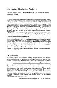
5. Experimental Evaluation In this section we discuss the results of our experiments with the setup presented in Sec. 3 implementing the distributed application from Fig. 4. We first compute the bound of the communication delay dM and compare it with the measured values. In the second part we give some experimental evidence that the requirements for the timely deterministic event-triggered system given in Sec. 2 are satisfied in this setup.
events). In this example, the input events on both nodes are generated with the period T=1ms. The delay D (Fig. 4) is set to 950µs, so that the output event for the previous cycle could be shown on the same scope plot preceding the next input event for 1000-950=50µs. All figures show exactly this delay with 0.1µs accuracy. Fig. 11 and 12 illustrate simultaneity requirement. In this example, events on node 1 have higher processing priority when occurring at the same time (within very small pre-specified interval) as events on node 2. As shown on Fig. 12, even if the input event on node 2 occurs about 2µs before the input event on node 1, the controller node 3 has to process it later and additionally delay the output on node 2. 450 400 350 300
Count
250 200 150 100 50 0 360
380
400
420
440 Time [us]
460
480
500
520
Figure 6. Communication delay dM histogram. 90 80 70 60
Count
For the communication delay measurements both node 1 and node 2 send frames of N=1000 bytes every T time units. The experiments were repeated tens of thousands of times for three different values of T (1ms, 0.5ms, 0.2ms). The arrival times were registered on node 3 and the maximum value of the measured delay is shown in Tab. 1 under column dM. Fig. 6 shows a histogram of the measured delay for T=1ms. For the estimation of the delay bound dM we follow the procedure from Sec. 4 and first estimate each partial delay. Fig. 7 shows the histogram of the measured interrupt latency. The interrupt latency was measured in experiments with very high CPU utilization by comparing the event time stamp registered by the FPGA hardware with the corresponding interrupt routine start time instant. From Fig. 7 we conclude that dint=55µs. In this analysis we further assume that the network driver delay is twice the value of the traffic shaping interval Ts in order to take into account also the receiver side delay. Since Ts was set to 100µs we have ddrv=200µs. The Fast Ethernet link bandwidth B is 100Mb/s, so dfrm=N/B=80µs. The switch multiplexing delay bound was estimated to be dmux=60µs in a series of experiments in which we compared the delays between the two nodes connected with and without the switch. Finally, the switch delay dsw and the total communication delay dM are calculated using the expressions from Sec. 4 and the corresponding values are given in Tab. 1. The last column of the table shows the relative difference between estimated and measured values of the communication delay. Such numbers are expected since all steps taken during estimation, including the network calculus procedures, result in conservative upper bounds. The difference increases as rates of flows decrease. This only means that the rare worst cases that the analysis has to take into account are even less likely to occur in the experiments with smaller traffic rates. T[ms] ρk[MB/s] σk[B] dsw[µs] dM[µs] dM[µs] ∆[%] 1 1 1614 318 653 510 22 0.5 2 1714 334 669 550 18 0.2 5 2014 382 717 610 15
50 40 30 20 10 0 20
25
30
35 40 Time [us]
45
50
55
Figure 7. Interrupt latency histogram. Table 1. Estimated and measured delay.
50
40 Counts
The figures 9-12 show that all three requirements (time, order and simultaneity) discussed in Sec. 2 can be achieved with less than a microsecond accuracy which is close to the synchronization accuracy. The histogram of the synchronization precision P is shown in Fig. 8. The precision was measured in an experiment in which one node directly triggers the other node. It is clear that the deviations between the clocks in this network with a conventional switch are less than a microsecond. Fig. 9 and 10 illustrate bounded delay time and event ordering requirements. The figures show periodic instances of event pulses (wider pulses represent input
60
30
20
10
0 -800
-600
-400
-200
0 Time [ns]
200
400
600
800
Figure 8. Time-sync. precision histogram.
Figure 9. Time and order requirements. IN1 before IN2.
Figure 10. Time and order requirements. IN1 after IN2.
Figure 11. Simultaneity requirement. IN1 before IN2.
Figure 12. Simultaneity requirement. IN1 after IN2.
6. Conclusion In this paper we focused on locally distributed systems that have to process events in the strict order of their occurrence and with certain timing guarantees. We implemented and evaluated such a system that uses open software with real-time extensions and standard networking components equipped with a time synchronization protocol. An important part in this solution is the estimation of the communication delay bounds that are directly used for the event scheduling decisions. We were able to accomplish the level of event processing determinism typically associated with the time-triggered approaches, keeping the flexibility and
simplicity at the same time. However, we noticed that with the decrease of the traffic load the estimated upper delay bounds become conservative, which may result in performance degradation. Also, this approach does not address fault-tolerance run-time mechanisms. Thus, achieving timely behavior requires components behave the way they are specified in the delay estimation step. Two extensions of this work are worth mentioning for future research. One direction is studying the effects of more complex network topologies where the issues of time synchronization become more important. There exist research results in applying the network calculus theory for cases beyond simple star topology [13].
This paper considers only a very simple type of distributed applications. Each node runs a single event processing task and the network traffic is simple. More complex applications require more complex local event scheduler. The relevant dependency relation and other theoretical concepts were developed within the Programming Temporally Integrated Distributed Embedded Systems project [14]. However, there are several concurrency issues to be resolved for implementations of such solutions, including various combinations of interrupt preemption and prioritization, safe event queue operation, and locks on thread rescheduling during nested interrupt handlers. References [1] M. Felser, “Real-Time Ethernet - Industry Perspective”, Proceedings of the IEEE, vol. 93, no. 6, pp. 1118–1129, 2005. [2] http://www.profinet.com/ [3] H. Hoang, M. Jonsson, U. Hagström, A. Kallerdahl, “Switched Real-Time Ethernet with Earliest Deadline First Scheduling − Protocols and Traffic Handling”, in Proc. IPDPS, 2002, pp. 94-99. [4] http://www.ethernet-powerlink.org/ [5] K. Steinhammer, P. Grillinger, A. Ademaj, and H. Kopetz, “A Time-Triggered Ethernet (TTE) Switch”, in Proc. DATE, 2006, pp. 794–799. [6] H. Kopetz, A. Ademaj, P. Grillinger, and K. Steinhammer, “The Time-Triggered Ethernet Design”, in Proc. ISORC, 2005, pp. 25–36. [7] J. Loeser and H. Haertig, “Low-Latency Hard RealTime Communication over Switched Ethernet”, in Proc. ECRTS, 2004, pp. 13–22. [8] H. Kopetz, Design Principles for Distributed Embedded Applications, Springer, 1997. [9] Agilent Technologies, IEEE 1588 Demonstration Kit, 2005. [10] J.C. Eidson, Measurement, Control and Communication Using IEEE 1588, Springer, 2006. [11] P. Gerum, “Xenomai – Implementing a RTOS emulation framework on GNU/Linux”, 2005 [12] J.Y. Le Boudec, P. Thiran, Network Calculus, LNCS vol. 2050, Springer Verlag, 2001. [13] J.P. Georges, E. Rondeau, T. Divoux, “Evaluation of Switched Ethernet in an Industrial Context by Using the Network Calculus”, in Proc. WFCS, 2002, pp. 19-26. [14] Y. Zhao, J. Liu, and E. A. Lee, “A Programming Model for Time-Synchronized Distributed Real-Time Systems”, in Proc. RTAS, 2007, pp. 259–268.