While there is no universal approach to this synthesis, a number of technologies have emerged: SunSoft's Java,. Microsoft's DCOM, and OMG's CORBA, to name ...
Engineering Component-Based Systems with Distributed Object Technology Kurt Wallnau, Edwin Morris, Peter Feiler, Anthony Earl, and Emile Litvak Software Engineering Institute, Carnegie Mellon University, Pittsburgh, USA Abstract. Distributed object technology (DOT) is the synthesis of object technology and distributed systems technology. While there is no universal approach to this synthesis, a number of technologies have emerged: SunSoft’s Java, Microsoft’s DCOM, and OMG’s CORBA, to name just a few. The recent explosion of the worldwide web has given impetus to the adoption of DOT. In this paper we survey a broad range of implications concerning the use of DOT for integrating systems from large-scale software components. We discuss the architectural implications of DOT in terms of design patterns and middleware, and highlight the pragmatics of encapsulating components with DOT. We describe recent experiments we have conducted concerning interoperation among different DOTS. Finally, we outline some techniques that we have found to be useful for keeping abreast of the quickening developments in DOT.
1
Distributed Objects and Component-Based Systems
Distributed object technology (DOT)—the marriage of object technology with distributed systems technology—represents a significant advance in software technology. The recent emergence of the worldwide-web—web browsers and open protocols such as HTTP, has given added impetus to the adoption of DOT. It is our belief that the synthesis of technologies such as objects, distribution, hypertext, open protocols and browsers will continue over the next few years, and promises to revolutionize the kinds of large-scale software applications that we develop, and the way in which we design and implement them. In this paper we focus attention on the impact of DOT on the development of component-based systems (CBS)[1]. In our work, component-based systems are those systems that are predominantly assembled from off-the-shelf components, where these components: exhibit significant aggregate functionality and complexity (e.g., database management systems, geographic information systems); are regarded as black boxes for integration purposes; and execute in heterogeneous environments. Distributed object technology is important for CBS because it: • enables us to embrace design concepts that are more powerful than functional approaches typically used when integrating off-the-shelf components; • has a profound impact on re-engineering decisions concerning re-implementation vs. restructuring by encapsulation of components; • directly addresses technical issues of distribution and heterogeneity that are central to our conception of CBS.
To appear in Lecture Notes on Computer Science, Springer-Verlag
Section 2 discusses the impact of DOT on the design of CBSs, centering on issues of software architecture and design patterns. Section 3 highlights practical aspects of component wrapping, by describing the implementation of a design pattern described in Section 2. Section 4 takes up the question of interoperability among different DOTs (CORBA, Java, and Microsoft’s COM). Section 5 steps back from the details of DOT to describe techniques for understanding and exploiting the rapid evolution—and synthesis—of DOT technologies. In Section 6 we summarize the key points of this paper.
2
Impact of DOT on the Design of Component-Based Systems
The 1990’s has seen considerable focus of attention on the topic of software architecture. While many different perspectives on the topic exist, there is general agreement that software architecture deals with design abstractions for system-level concerns, i.e., something larger than a single computer program. As noted by Garlan and Shaw [2], such issues include “gross organization and global control structure; protocols for communication; synchronization, and data access; physical distribution.” DOT provides mechanisms that address many of these concerns in a way that builds upon already proven abstraction mechanisms available in object technology (OT). The significance of these distribution extensions to OT is that software designers now have at their disposal the means of expressing abstract system designs and, more importantly, now have tools for quickly fabricating working versions of these designs. That is, there is a more direct path now than ever before from abstract architectural concepts to concrete implementation of these concepts. To explore the impact of DOT on architectural aspects of CBS we examine two characteristic elements of CBS architecture: design patterns for component encapsulation, and distributed middleware for the integration of encapsulated components. We illustrate the central ideas through example systems, focusing on high-level architectural issues at the expense of discussing implementation details. 2.1 DOT Design Patterns for Component Encapsulation The notion of design pattern has been embraced by the OT community as a means of expressing reusable design abstractions that solve specific, well-bounded problems [3]. We believe that the application of design patterns to component encapsulation is understudied, and that design patterns based on DOT can extend, and help formalize, our conceptualization of component encapsulation and integration. To illustrate, we distinguish between two broad categories of encapsulation: functional, and structural. Functional encapsulation translates an application interface (i.e., what it does) from one mechanism for accessing component functionality to another. For example, a compiler can be encapsulated so that requests to it can be delivered from a publish/subscribe service in addition to the usual command-line requests (i.e.,the un-encapsulated component). We refer to this as a functional encapsulation because the interface to the encapsulation reflects the functionality of the component being encapsulated. In contrast, structural encapsulation translates functional interfaces to interfaces that describe a coordination model, i.e., a model that defines how components interact regardless of their functionality. The encapsulation of a compiler as a filter in a Unix pipe and
To appear in Lecture Notes on Computer Science, Springer-Verlag
filter model (see [2]) is a simple illustration of a structural encapsulation. In this illustration the interface to the encapsulated component is based on Unix pipes, while the functionality of the underlying compiler is implicit in the protocol used within the overall coordination model—source code delivered via pipe as input to the filter, object code delivered via pipe as output from the filter. There are pros and cons to both functional and structural encapsulations. Functional encapsulation provides multiple mechanisms to access the same component functionality. Structural encapsulations, however, are more germane to architecture-level design issues, especially those that arise in distributed, heterogeneous systems—for example, how components executing remotely synchronize their activities. Since DOT addresses heterogeneity and distribution, it seems natural to employ it via structural encapsulation. It can also be argued that functional encapsulation is redundant since (presumably) the functionality of a particular off-the-shelf component is known a priori, while the coordination model it implements is usually implicit in its function-oriented APIs—in the same way that functionality is implicit in the structure-oriented pipe/filter illustration, above. The ConsistencyManager pattern illustrated in Figure 1 is a structural encapsulation Consistency
OutputQueue
ExternalState() Instruction() Update() Status?() Consistent?()
PushEvent() PullEvent() ...
various types of OMA event channel
ComponentA
ComponentB
ExternalState() Instruction() Update() Status?() Consistent?()
ExternalState() Instruction() Update() Status?() Consistent?()
execute operation write output to channel
Fig. 1. ConsistencyManager Pattern for Structural Encapsulation pattern that is designed to enable long-running, stateful components to interact via potentially unstable wide-area network connections [4]. Each component is modeled as a state machine that accepts some input specification, and executes an update operation to make this externally-specified data consistent with some internal state. The component can be in various states: it can be active (i.e., currently updating) or inactive; if inactive it can be consistent (the derived state matches the externally specified state) or inconsistent. Data generated as a result of an update, which may execute over a period of hours or days in the case of computationally intensive algorithms such as finite element analysis, is queued to an event channel, of which many varieties with alternative coordination models are defined by the Object Management Group’s (OMG) Object Management Architecture (OMA) [5]. This pattern is quite general, and can be used to encapsulate any component
To appear in Lecture Notes on Computer Science, Springer-Verlag
that maintains internal state that depends upon some input data, and for coordinating the execution of several of these encapsulated components in a distributed system. DOT does not require that a system make exclusive use of either functional or structural encapsulation; in fact, it may be desirable to use both forms of encapsulation. One design that illustrates this point was developed by a vendor in the document printer industry (referred to hereafter as PCo). PCo was attempting to develop a software product line for a family of printers. What distinguishes high-end printers from less expensive printers is speed—simply put, pages per minute. Thus, one design objective was to ensure that printer software could be configured for various degrees of concurrency, depending upon available computing resources (high-end printers, for example, might employ as many as 20 SPARC processors running in a shared-memory configuration). Another design objective was to maximize software reuse across printers by code factoring and unit replacability—strategies typical of object-oriented and product-line thinking. Figure 2 depicts the DOT-based architectural concepts used to satisfy these twin design objectives (performance and unit replacability). In this design both structural and functional encapsulation are used in a two-level (nested) design pattern. The top-level pattern (the Coordinator pattern) is structural; it defines objects that are used to channel data to software executing on particular processors. The Coordinator pattern is foData Flow... con_status?
pro_status?
data_input
register_for
instruction
data_output
Coordinator objects Functional objects
Fig. 2. Hybrid Patterns for Distributed, Concurrent, Embedded Processing cused on design issues relating to performance and concurrency, and makes the design amenable to be analyzed and tuned along these lines. As with the Consistency pattern, Coordinator objects provide functions to route data to an object (data_input), probes for determining the execution state of objects (con_status and pro_status, for status on producers and consumers, respectively), and an operation for passing specific computation instructions to the object (instruction). Parallel operations are defined to allow objects to act as both producers and consumers of data. One metaphor used by the designers to describe this pattern was “pushing data through logic.” The structural pattern was used to encapsulate one or more functionally-encapsulated objects. The PCo architecture exploits another feature of DOT that is derived from its OT heritage: the ability to define a highly-factored class lattice. Thus, in addition to defining a top-level design pattern that is focused on performance considerations, PCo also uses OMG’s Interface Definition Language (IDL) to model the functionality of the printer domain. This model expresses a deep, rich class hierarchy; plug-replaceable components implement these classes, and are “plugged into” the overall printer architecture as defined by the Coordinator pattern. These function-oriented interface definitions round out the
To appear in Lecture Notes on Computer Science, Springer-Verlag
overall architecture, which now addresses both functional (product-line reuse) and structural (performance) aspects of the design. The reader will have noticed that different conventions are used to illustrate the Coordinator and ConsistencyManager patterns. This is intentional, because Figure 2 reflects the way the PCo designers described their design—as nested objects, like a Russian doll. We have preserved this metaphor (although we have simplified its presentation) in order to highlight the way in which DOT can be used as a bridge between the abstract metaphorical concepts that are essential to intellectually grasp the architecture of a system, and the concrete implementation of these metaphors as software objects. 2.2 DOT for Distributed Middleware Another important architectural concept for CBS that is often (but not always) used in conjunction with component encapsulation is middleware. Although middleware is broadly defined [6] the use of a variety of commercial products purporting to be middleware is no longer an exceptional occurrence—in fact, it is increasingly commonplace, and usually well-motivated. For example, publish/subscribe middleware products allow a looser coupling among components and the definition of message sets for classes of components; taken together, these go a long way towards plug-interchangeable software components. As is the case with design patterns for encapsulation, DOT may influence our thinking about the role and construction of middleware. To explore this possibility we start with an abstract view of middleware, at least from the CBS perspective. We think that Figure 3 is a reasonable place to start because it is consistent with middleware products with components bridges, wrappers, agents mediators, ambassadors, encapsulators, proxies,...
optional middleware service core middleware services
{
Application-Specific Services General Integration Services Fig. 3. A General View of Middleware
which we are familiar, and because it distinguishes middleware features that are useful for understanding the role of DOT for implementing middleware. At the topmost level there are components which we intend to integrate. Between these components and the core middleware are encapsulation services: these may be provided by the middleware, or they may need to be developed by the integrator. Encapsulation services go by many names: glue, wrapper, agent, mediator, proxy, encapsulation, ambassador, and probably others. While these terms may have precise meanings in some contexts, overall they are used without any great uniformity. The core services consist of basic integration services (e.g., publish/subscribe), and higher-level services that facilitate integration within specific application domains.
To appear in Lecture Notes on Computer Science, Springer-Verlag
As in the discussion of component encapsulation, we illustrate by example how DOT can be used to implement each of the “layers” depicted in Figure 3. We use for our illustration a prototype middleware system that we developed in order to evaluate the viability of using the OMA to support wide-area distributed workflow management [7]. Although the system we describe is just a partially-implemented research prototype, it is representative. See [8] for an industrial-strength illustration of these same concepts in the domain of real-time, distributed simulation. Figure 4 depicts the most relevant aspects of the prototype workflow management middleware in terms of the general middleware model from Figure 3. Our prototype demonstrated the integration of three kinds of workflow process definition component
process execution component
process participation component
stub
stub
stub
request
install
request
Agent Services
manage
Workflow Management Services
OMA Integration Services
read/write process state
admin. objects activity objects
data model/persistence, naming service lookup
workflow engine objects
retrieve done tasks persistence for event queues
OMA relationships, persistence, naming, properties, etc.
—OMA Object Service
client application objects
post new tasks
engine’s event channel objects
post done tasks
retrieve new tasks
client’s event channel objects
—OMA Application Object
Fig. 4. CORBA-Based Middleware for Workflow Management management components: process definition components which define workflow models, process execution components which interpret and manage the state of workflow models, and process participation components which provide task-oriented end-user interfaces. Process execution and participation components were plugged into the middleware via agents—CORBA objects that represented these components within the middleware. A different mechanism (mediators) was used to plug process definition components into the middleware—mediators would allow alternative process definition formalisms to interoperate. The mediator services were not fully implemented and are therefore not depicted in Figure 4. Using agents meant that the components being integrated could be implemented as pure clients of the middleware, which greatly simplifies component integration: the agents were server objects that could receive requests, while the client components could decide when to retrieve these requests. Having the middleware manage the agents has other advantages as well, including centralized security and process management policies. Agents, administrators, and activities (objects that model workflow processes) comprised the application-specific layer of the core middleware.
To appear in Lecture Notes on Computer Science, Springer-Verlag
The OMA provided the general integration services. OMA event channels reduced the need for synchronous communication so that workflow execution could continue even in the face of network partitions that isolate groups of participants from each other. Location transparency provided by CORBA simplified the creation of participant topologies: engine and participant event channels could reside on distant machines as easily, and as transparently, as if they resided on the same machines. Other OMA services, such as persistence, relationships, and naming provided general-purpose integration services upon which the more application-specific workflow services were constructed. Agents were defined via structural encapsulation patterns. In addition to earlier arguments made regarding structural encapsulation, we believed that these patterns provided the best means of guarding against skewing of the middleware toward functionality peculiar to one or more workflow component vendors. Similarly, structural encapsulation might also provide some insulation against the inevitable introduction of new component features—a basic coordination model is likely to be more stable than the components themselves. Figure 5 illustrates the structural interfaces used for the agents, and shows the
❶
❷
from process definition tool
Engine Component
❶
involve_user
register_process
terminate_process
register_user
authorize_activity
❹
❹
Participant
Engine
Admin launch_process
Participant Component
❸ invite_participation
❺ ❹
process_completed commit_activity
❹
“chained” event channels
Fig. 5. Structural Encapsulation of Workflow Components basic sequencing of the application-level coordination model as numbered steps. Thus, workflow models and participants are registered, perhaps concurrently, as a first step. Participant registration results in the creation of a participant agent, which is used by an engine agent (previously registered on the Admin objects, although this is not illustrated) to invite a participant into a workflow; once the invitation is accepted an engine/participant event channel chain is established. Further details can be found in [7]. On the whole, the proximity of DOT to issues of software and system architecture, including distribution, coordination, and heterogeneity, offers software designers new mechanisms for expressing and implementing innovative, application-specific designs. This is certainly true of CBSs, where new approaches to encapsulation and integration via distributed middleware seems not only possible, but increasingly commonplace.
To appear in Lecture Notes on Computer Science, Springer-Verlag
3
Pragmatics of Encapsulating Components for DOT
A number of DOT design concepts were described in the previous section. Ultimately, however, a critical determinant of the suitability of these design concepts will be the economics of component encapsulation. It is important that we begin to develop a better understanding of the cost factors associated with encapsulation. We might start to develop this understanding from a theoretical standpoint. For example, the fact that we need to encapsulate a component implies that the component, in its original (un-encapsulated) form, is somehow mismatched to its new intended operating environment. Encapsulation, then, is the technique to remove mismatches between components [9], as for example between an off-the-shelf component and some middleware service. The cost of encapsulation will be proportional (in some way) to the amount of adaptation—i.e., mismatch removal—that must be performed. Assuming this to be true, this raises some interesting questions regarding the use of structural versus functional encapsulation patterns. Recall that earlier we argued that functional encapsulation of off-the-shelf components was redundant, while structural encapsulation abstracted over an orthogonal (to functionality) range of design issues. When considering the cost of component encapsulation, the flip-side of this argument may hold true—the development cost of functional encapsulation will be less than that of structural encapsulation, since translating from one functional interface to another frequently requires less mechanism than imposing a uniform coordination model on components that implement disparate coordination models. Although this cost argument might not always hold true, this proved to be the case in a prototype integration of Sandia National Labs SEACAS components [4]. Figure 6 provides a cutaway view of components encapsulated by the ConsistencyManager pattern (refer to Figure 1). A few details about the components, the integrated system, the system coordination model, and ORB limitations are required before proceeding to a description of this illustration: • Some of the components being encapsulated were highly interactive (e.g., 3-D display tools), while others were computationally-intensive and long-running (e.g., finite element analysis tools running for several hours per-simulation). • The integrated system supported interaction among encapsulated components running remotely from each other on a wide-area, and potentially unreliable, lowbandwidth network. Design sessions might last hours, days, or weeks. • The coordination model emphasized asynchronous or very lightweight interaction among objects. For example, the update() operation was synchronous, but did not wait for completion of an update (which might take hours to complete). • The commercial ORB we used did not support multi-threaded servers, or provide much support for persistence. For various reasons both were required to implement the coordination model, and thus both became elements of the encapsulation. The above details are sufficient to illustrate that “component mismatches” are not just bilateral between two integrated components, but multi-lateral. For example, there are mismatches between the components to be encapsulated and the coordination model: the components were not designed to run in a wide-area distributed system, or to be viewed in object-oriented terms. There are also mismatches between the ORB and the coordina-
To appear in Lecture Notes on Computer Science, Springer-Verlag
tion model: single-threaded ORB servers would cause blocking on long-running tool executions. Additional mismatches arose between the operating system and the coordination model: Unix signals and other process status indicators were not always well-matched to the states defined on the ConsistencyManager pattern. Finally, there were mismatches between the component and the ORB: in particular, the way a component reported anomalous behavior, e.g., Unix errno vs. CORBA exceptions. The cutaway (Figure 6) describes the encapsulation via layers, with each layer corresponding to some aspect of component mismatch. The bottom two layers resolve mismatches between the ORB and coordination model, the next layer removes mismatches between the ORB and the encapsulated component, and so forth. The numbers indicate a rough sequence of control flow through the these layers. In step ①, a request on an enObject Server
Component Mismatches Repairs component/coordination • updates as transactions OS/coordination • process state to object state ORB/component • data parsing to exceptions and object state ORB/coordination • multi-threaded server for multi-user objects
{ { {
{
②
③
update
Process Harvester
⑥
Component fortran program
100111 111001 110000
④
⑤
Component Data Harvester Adaptor Homegrown Asynchronous I/O Event Manager ORB-Vendor Connection Management
“/bin/tail -f”
UNIX socket 100111 111001 110000
① Fig. 6.
UNIX data file UNIX process
Pragmatics of Structural Encapsulation
capsulated component is received from a client. Since the ORB is not multi-threaded, we needed to detect these requests and do our own multiplexing; we did this by using a conventional Unix programming technique involving asynchronous I/O, and by exploiting ORB features that provided programmatic access to the sockets that connect objects to clients. Steps ② and ③ perform various consistency and locking steps, and ultimately execute the component via a fork/exec. Steps ④ through ⑥ manage one or more Unix processes that are associated with the update() operation. Fuller details of this implementation can be found in [4]. The key point to note that the encapsulation was not a trivial matter, and required significant expertise in Unix, the CORBA specification, ORB product internals, and numerous aspects of the components themselves. It is quite likely that a simple functional encapsulation would have been less costly to develop (although even then some of the above mismatches would still apply). The choice of structural over functional encapsulation, then, will be governed by the degree to which the system design needs make explicit the policies regarding the interaction of components. Alternatively, the choice of structural versus functional encapsulation may be indicated by which aspect of the system is likely to remain, or needs to remain stable. Design elements hardened into interfaces as opposed to left implicit in protocols are going to be more difficult to change. To appear in Lecture Notes on Computer Science, Springer-Verlag
4
Interoperability of Distributed Object Technologies
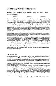
The SEACAS encapsulations described in the previous section provides an example of wrapping a legacy system with DOT in order to make non-distributed components available in a distributed environment, and to improve their overall integration. However, the rapid evolution of DOT quickly turned the newly encapsulated and integrated SEACAS system into a legacy system. In particular, new releases of the CORBA product we used had become available, and several new mechanisms to enable greater interoperability between DOT infrastructures had emerged. First, CORBA 2.0 compliant implementations had become available that implement the Internet Inter-ORB Protocol (IIOP)—a protocol that promises interoperability of different vendor ORBs. Thus, a client using one vendor’s ORB could access objects implemented with another vendor’s ORB. Second, the emergence of Java technology during this time period offered new opportunities for creating platform independent user interface clients that are distributable over the Web; in addition, various techniques for combining Java and CORBA had become available. Finally, bridges between CORBA and Microsoft’s COM technologies were released that opened doors for making SEACAS available directly to client applications without resorting to Java and browsers. This rapid evolution of DOT and the continuing trend toward heterogeneous computing environments makes it clear that it is not sufficient to select a single DOT for encapsulating legacy systems; in all likelihood the selected technology will be overtaken and surpassed by alternate technologies on at least some platforms. If this is the case, an important consideration during the design of distributed object systems must be the potential for interoperability between alternate DOT technologies. Such interoperability is not assured, since the alternate technologies differ along a wide range of dimensions, including object models, data mappings, communications protocols, security mechanisms, and even the favored system architecture. Nevertheless, there are strong market pressures on all DOT vendors to insure interoperability among DOTS—what is in question is under whose terms this interoperability will occur. To assess the state of inter-DOT interoperability, we constructed three experiments based on the (by now) legacy SEACAS encapsulations: • A Java-based ORB client referred to as orblet. This results in a platformindependent client that uses Java and web browsers for user interaction, and that interfaces client-side ORB libraries written in Java. • A Java-based front end using Java Remote Method Invocation (Java RMI). This results in applets that have no knowledge of CORBA, and that use an intermediate server that map between CORBA objects and Java objects. • A Visual Basic front end that interfaces CORBA objects via OLE. This results in a PC-based OLE server that maps CORBA object access into OLE objects, and makes those objects available to PC presentation tools via COM services. These three scenarios are illustrated in Figure 7, which shows the three scenarios running horizontally, while host machines connected via LAN are shown vertically. Clients and servers are illustrated abstractly as rectangles with rounded corners. The circles contained within these clients and servers represent objects, and these objects interact with remote objects via the protocols that label the double-headed arrows that connect ob-
To appear in Lecture Notes on Computer Science, Springer-Verlag
network boundaries Solaris 2.4
SUNOS 4.1.3
PC/Windows-NT
IIOP Applet using CORBA/IIOP “ORBlet”
IIOP PP
legacy SEACAS objects
shadow SEACAS objects
PP COM CORBA/COM Bridge
Visual Basic Client using COM
RMI Scenario Orblet Scenario COM Scenario
Applet using Java/RMI
RMI
shadow Java objects
Fig. 7. Inter-DOT Interoperability Scenarios jects—IIOP, RMI, and proprietary Orbix protocol (PP). In the following three sections we elaborate on our experiences in developing prototypes for each of these scenarios. These descriptions are experience reports of using DOT products at a particular point in time. Our objectives in conducting these experiments were modest: we were really seeking to become familiar with inter-DOT plumbing, and accordingly focused most of our efforts on low-level, messy details—as you might expect with a plumbing job. 4.1 The Orblet Scenario An orblet is a Java applet that can interact with (remote) CORBA objects. The combination of CORBA and Java seems quite natural, and numerous arguments can be made concerning the utility of integrating Java and CORBA, for example combining small, mobile Java objects with large, immobile CORBA objects. One technique used to integrate Java and CORBA is simple—the ORB vendors rewrite their client-side libraries in Java. These libraries are delivered to the running applets, which then use the basic socket connection services provided by the Java runtime environment to communicate with remote CORBA objects using IIOP. Another technique for integrating CORBA and Java involves IIOP tunneling—embedding IIOP messages within HTTP. This technique is useful for dealing with firewalls, but obviously requires the use of an HTTP server that understands tunneling. Such servers exist, but we did not use them In this scenario we used both Iona’s OrbixWeb and SunSoft’s Joe. Before we could write SEACAS orblets we needed to modernize the SEACAS encapsulations, as the ORB version we used to implement these encapsulations did not support IIOP. We had two choices: we could re-compile the legacy SEACAS servers with the
To appear in Lecture Notes on Computer Science, Springer-Verlag
new IIOP-compliant version of the ORB, or we could encapsulate the legacy objects in objects that support IIOP. We choice to encapsulate for several reasons. First, the new version of the ORB was not wholly upward compatible with the previous release—we did not wish to revisit the details of the ConsistencyManager implementation. Second, the new encapsulation was bound to be very thin, mostly concerned with exporting an IIOPcompliant interface; thus the cost of encapsulation versus re-compilation seemed attractive. Since we were not dealing with a high-performance application (users execute SEACAS services via a WAN, after all), the performance overhead incurred by an extra object invocation seemed acceptable. To get the most from this interoperation experiment, we not only combined Java and CORBA, but also combined different implementations of CORBA. For our IIOP encapsulation we used Orbix v2.1. This was necessary since the legacy encapsulation used Orbix v1.3, and we needed to use the proprietary Orbix protocol to access these legacy objects. However, on the orblet side we used SunSoft’s Joe. Thus, SunSoft’s client-side ORB libraries were used to access, via IIOP, Orbix objects that, in turn, used PP to access the legacy objects. While this worked well for the most part, interoperability was hindered by a lack of standardization of higher level services, differing IDL bindings, and inconsistent client-side class structures. However, while we experienced problems, we were ultimately able to glue the system together, in spite of the fact that a number of the technologies used were in Beta release—and in spite of the fact that several versions of these Beta products were released during the eight weeks comprising our effort! The orblet approach allowed us to create a thin client which consists of nothing more than a Java GUI and ORB capability running in web browser. The resulting orblets could be downloaded from the HTTP server machine, and provided direct access to our shadow and indirect access to our legacy servers. 4.2 The Java RMI Scenario Java RMI is a distributed object model for the Java language that retains the semantics of the Java object model, making use of distributed objects as transparently possible. RMI has become part of the official Java v1.1 specification. Two forms of distributed objects are supported by RMI. First, copies of Java objects can be passed as parameters to other, potentially remote, processes. Second, a reference to a Java object that has been declared to be a remote can be passed to other, potentially remote, processes. The remote process invokes methods, performs operations, and does exception handling as if the object were local. Java RMI follows the client/server model in that method invocations on remote objects are routed to a server process on a machine where the remote object resides. All communication is performed through a particular (RMI) port. If firewalls prevent the use of this port, Java RMI transparently embeds (tunnels) the RMI request in a HTTP request. Stubs and skeletons for remote objects are dynamically loaded. The starting point for our Java RMI scenario implementation was the orblet implementation discussed in section 4.1. In that implementation the client takes advantage of the platform independence of Java by utilizing a Java implementation of an ORB interface, which interfaces to the ORB server via IIOP. The use of Java RMI allowed us to investigate several additional issues, including interoperation between two distributed object models (CORBA and RMI), increased separation of concerns and modularization
To appear in Lecture Notes on Computer Science, Springer-Verlag
of the application, increased platform independence of the application by introducing a platform independent server, and a still lighter-weight client. We developed a shadow Java objects server that has the knowledge of interfacing with CORBA ORBs. The shadow Java objects server is both an ORB client and a RMI server simultaneously, and maps between CORBA and Java objects. Since the shadow Java objects server was constructed using SunSoft’s Joe (i.e., Joe provided the Java client libraries that use IIOP), it potentially can be downloaded and executed on another platform, although we did not test this capability. Note that the shadow Java objects is a client of the shadow CORBA server rather than the legacy CORBA server; this was necessary because Java-based development tools are not available to interface to the legacy server platform. The RMI-based applet is retrieved by the client browser from the HTTP server; it establishes a connection with the shadow Java server through the RMI naming services. While many aspects of Java have reached a level of stability such that customers are beginning to build serious systems, Java RMI is still a rapidly evolving technology. One area of Java RMI that is still evolving is the interaction of distributed objects, dynamic loading of classes, and security concerns. Mapping between the Java RMI and CORBA object models was not troublesome. However, the experiment highlighted design issues regarding the assignment of responsibility to various system components, and the resultant ramifications on DOT interoperability. In keeping with the basic design philosophy of web browsers and the downloading of applets, we developed a very “thin” Java RMI client with little functionality beyond the user interface. This preferred architectural model of the Java RMI approach was in direct contrast to the preferred approach in the “thick” client experiment (section 4.3) where the rich PC operating environment naturally led to a tendency to increase the responsibilities of (i.e., “thicken”) the client. 4.3 The OLE/COM to CORBA scenario The OLE/COM to CORBA scenario exercises an “interoperability bridge” between Microsoft/COM and CORBA. The bridge technique and a detailed COM/CORBA mapping is part of the specification of CORBA 2.0. We used the Orbix Desktop for Windows 2.0.2. implementation of this CORBA/COM bridge. Unlike the other experiments, which use IIOP interfaces between clients and servers, the OLE/COM to CORBA bridge uses PP—support for IIOP is promised for subsequent versions of this product. To provide programmatic access to the bridge an Orbix-OLE wizard (a code generator) is used. The wizard accepts as input OMG IDL and produces as output an OLE Server providing an OLE Automation interface corresponding to each IDL interface. For each remote (CORBA) object accessed by a PC client, a local OLE proxy object is created. Each client reference intended for the remote object is actually made as a reference to the local proxy object using standard OLE Automation syntax. The code for the local proxy objects is generated by the Orbix-OLE Wizard; in addition to acting as “servers” to the PC client, local proxy objects operate as CORBA clients. When an operation or attribute is invoked on the local proxy object, the proxy forwards the request to the real CORBA object via the Orbix ORB residing on the client platform. Thus, in contrast to the two thin client scenarios, this scenario required that an ORB be resident on the client host. The design of the OLE/COM to CORBA experiment scenario was straightforward; a Visual Basic client that mimics the user interface provided by the orblet client was built.
To appear in Lecture Notes on Computer Science, Springer-Verlag
This client was connected to the shadow SEACAS server. However, a major difference between this experiment and those involving Java-based clients was immediately apparent in our work. While Java-based clients tended to be thin, a Visual Basic client can be constructed to take advantage of the wealth of computing resources in the PC environment. For example, we elected to use the graphing capabilities of Excel to view the results of operations on SEACAS objects. Exploiting the resources of a PC client is not a priori bad design, but there are some obvious trade-offs regarding platform heterogeneity. While we were able to build a thick PC client that provided access to our shadow server, it was clear that the mapping between the Visual Basic/OLE/COM environment and the CORBA environment was not complete. The failure to completely map CORBA exceptions to the Visual Basic/OLE/COM world was particularly troublesome, since it interfered with our ability to debug the distributed system.
5
Accommodating Technology Evolution
Given the changing design metaphors, new cost equations, and emerging technologies associated with DOT, it is difficult for any organization to determine when any particular technology is appropriate for a specific use, particularly since scarcely a week passes without some new and often dramatic technology being released. Considering only internet technology, Applets, Beans, Orblets, Pointcast, Agglets and so forth are emerging from what can only be described as a technology “horn of plenty.” This startling pace is reflected in a new term, “internet years” e.g., one internet year equals seven weeks 1. A practical approach for assessing technology maturity and forecasting trends is needed. To address these needs we have developed a technique for performing situated technology assessments, i.e., assessments that determine whether a given technology is suitable for use in a particular setting, and how to best use the technology. The methods for performing situated evaluations, known as “technology delta” techniques, are described in [10]. One of the key ideas of technology deltas is to isolate the new or distinguishing features of a technology (its “delta”), and apply this delta to solve model problems in an application domain. Model problems describe key problems isolated from extraneous complications. For example, a model problem may involve assessing the technical and economic feasibility of wrapping a legacy database server with Java. An engineering solution for a large system involves far more than the sum of solutions to a set of model problems. However, the use of model problems allow the analyst to focus attention on narrowly defined problem settings, thereby providing greater precision in the construction of an evaluation experiment and in the interpretation of the results of the experiment. Model problems also economize effort; this is particularly important when evaluating fast-changing DOT. For fast-changing technologies, experiments based on model problems can be likened to single frames in a motion picture: each frame represents a “snapshot” of the state of the technology at a particular point in time. Like motion pictures, the value of each frame is realized most fully when each frame is linked with
1.
Scott McNeally, CEO of Sun Microsystems, at JavaOne stated that the internet is running in “dog years”, i.e., every internet year is about 7 weeks.
To appear in Lecture Notes on Computer Science, Springer-Verlag
candidate technologies
a series of related frames to give a sense of time and motion, i.e., how the technologies are evolving over time. The technology delta evaluation framework (Figure 8) embodies a number of important principles regarding technology assessment. First, of course, is the notion that the potential impact of a technology is best understood in terms of its feature delta. That is, while all of the features of a technology are relevant to understand the technology and how to apply it, to understand the value-added of a new technology it is essential to focus attention on its distinctive features, i.e., to discover its value-added with respect to some other technologies. This is particularly important with regard to DOT—a recent paper technology domain genealogy
problem domain habitat
Descriptive Modeling Phase
business objectives
situated technology comparative anatomy hypothesis formulation
experiment design
Experiment Design Phase
experiments and evaluation criteria compatibility study
benchmarks
model problems Experimental Evaluation other “lab” demonstrator Phase techniques study
technology assessment Fig. 8. Technology Delta Evaluation Framework listed thirteen mechanisms for providing inter-operation between Windows NT and Unix platforms without even listing DOT capabilities such as CORBA and Java/RMI [11]. Second, it is not sufficient to simply describe the distinctive features of a technology; it is also essential to evaluate these features in a well-defined and sharply-focused usage context. The technology delta framework exhibits a strong bias towards the use of rigorous experimental techniques for evaluating feature deltas. Specifically, hypotheses are formed about how a feature delta supports a defined usage context, and experimental techniques are then used to confirm or refute these hypotheses. We view the technology delta framework as addressing a necessary but not sufficient aspect of DOT evaluation. The framework is intended to address the technical aspects of determining valued-added, and leave questions pertaining to, e.g., technology transition and return on investment, to disciplines better equipped to deal with such issues.
To appear in Lecture Notes on Computer Science, Springer-Verlag
6
Closing Thoughts
Advances in distributed object technology have been dramatic in the past few years. These advances have been largely driven by increasing demand for component interoperability, heterogeneity, and distributability. The world-wide web has played no small part in conditioning end-user demand and, therefore, indirectly conditioning the demand of third-party integrators for more robust and open distributed object technology. It may be that the days of proprietary, closed systems and “vendor lock” are numbered, although the vested interests will not necessarily go quietly into the night. However, we are hopeful. In the meantime organizations will struggle with questions regarding the adoption of DOT. In this paper we have surveyed a number of topic areas in which such questions might arise in the context of CBS, i.e., implications of DOT on the design of CBSs, and the pragmatic aspects of encapsulation and interoperability among DOTs. We also briefly described some techniques that we have found useful in helping us to “step back” from the latest technologies and survey the fast changing technology landscape.
References 1.
Brown, A., and Wallnau, K.: Engineering of Component-Based Systems, Proceedings of the Second International Conference on Engineering of Complex Computer Systems, Montreal, Canada (1996) 2. Garlan, D., and Shaw M.: An Introduction to Software Architecture, Advances in Software Engineering and Knowledge Engineering (1), River Edge, NJ: World Scientific Publishing Company (1993) 3. Gamma, E., Helm, R., Johnson, R., and Vlissides, J.: Design Patterns: Elements of Reusable Object-Oriented Software, Addison-Wesley, ISBN 0-201-63361-2 (1995) 4. Wallace, E. and Wallnau, K.: A Situated Evaluation of the Object Management Group’s Object Management Architecture, in Proceedings of Object Oriented Programming Systems, Languages and Architectures (OOPSLA), USA (1996) 5. Soley, R. (ed.): Object Management Architecture Guide, John Wiley and Sons, Inc. (1995)S 6. Rymer, J.: The Muddle in the Middle, Byte Magazine, April (1996). See also The Middleware Riddle in the same issue. 7. Wallnau, K., Long, F., and Earl, A.: Toward a Distributed, Mediated Architecture for Workflow Management, in Proceedings of the NSF Workshop on Workflow and Process Automation in Information Systems, State of the Art and Beyond, see on-line proceedings at http://info.acm.org/coe/e7000010.html, USA (1996) 8. Calvin, J., and Weatherly, R.: An Introduction to the High Level Architecture (HLA) Runtime Infrastructure (RTI), in Proceedings of the 14th DIS Workshop on Distributed Simulation. 9. Garlan, D., Allen, R., and Ockerbloom, J.: Architectural Mismatch or Why It’s Hard to Build Systems Out of Existing Parts, Proceedings of the International Conferences on Software Engineering, Seattle (1995) 10. Brown, A., and Wallnau, K.: A Framework for Evaluating Software Technology, IEEE Software, September (1996) 39-49. 11. Auditore, P.: A Kludge Beyond Relief, HP Professional, January (1997) 28-36.
To appear in Lecture Notes on Computer Science, Springer-Verlag