Development of Digital Readout Electronics for the CMS Tracker
Emlyn Peter Corrin
High Energy Physics Imperial College London Prince Consort Road London SW7 2BW
Thesis submitted to the University of London for the degree of Doctor of Philosophy
November 2002
1
Abstract The Compact Muon Solenoid (CMS) is a general-purpose detector, based at CERN in Switzerland, designed to look for new physics in high-energy protonproton collisions provided by the Large Hadron Collider. The CMS tracker has 10 million readout channels being sampled at a rate of 40 MHz, then read out at up to 100 kHz, generating huge volumes of data; it is essential that the system can handle these rates without any of the data being lost or corrupted. The CMS tracker FED processes the data, removing pedestal and common mode-noise, and then performing hit and cluster finding. Strips below threshold are discarded, resulting in a significant reduction in data size. These zero suppressed data are stored in a buffer before being sent to the DAQ. The processing on the FEDs is done using FPGAs. Programmable logic was chosen over custom ASICs because of the lower cost, faster design and verification process, and the ability to easily upgrade the firmware at a later date. This thesis is concerned with the digital readout electronics for the CMS tracker, working on the development of the FED, and verifying that it will meet the requirements of the detector. Firmware was developed for the back-end FPGA of the FED, implementing the CMS-wide common data format. Each event is wrapped in a header/trailer containing information such as the trigger number, bunch-crossing number and error-detection information. The firmware was developed in VHDL, and will be incorporated into the back-end FPGA of the FED, both in the tracker, and in the other subdetectors. A study was performed, looking into the flow of data and buffer levels in the FED. A program was written in C++ that models the behaviour of the FED buffers. It was shown that during normal operation the FED can handle occupancies of up to 4 % with 100 kHz random triggers, assuming a sustainable output rate of 200 Mbyte/s. Even when the trigger rate was increased to its maximum of 140 kHz, the FED buffers did not overflow as long as the occupancy remained below 2.5 %. These results confirmed that the FED buffers should never overflow in normal operating conditions.
2
Acknowledgements I would like to thank everyone in the High Energy Physics group for their help and support during my three years there. In particular Geoff Hall for his supervision and guidance, Costas Foudas for his help and for spending so much time proofreading my thesis, and Peter Dornan for letting me work with the group. Thanks also to John Coughlan, Rob Halsall, Bill Haynes, Peter Sharp, and Mike Johnson at RAL. I would also like to thank the Particle Physics and Astronomy Research Council (PPARC) and the Rutherford Appleton Laboratory (RAL) for funding my project. I would especially like to thank Greg, Mark, Barry, Jonni, Etam, Rob, and Matt for the great atmosphere both in the lab and also over a coffee or a pint. Above all I would like to thank my girlfriend Sandra for her help and moral support while writing my thesis. Thanks also to my grandmother Win, my sister Naomi, my mum Marie-Pierre, Laurent, and all the rest of my family. I dedicate this thesis to my dad, Ian, and my grandfather, George, for inspiring me towards an inquisitive mind.
3
Contents Abstract....................................................................................................................2 Acknowledgements..................................................................................................3 Contents ...................................................................................................................4 List of Figures..........................................................................................................8 List of Tables .........................................................................................................11 Glossary .................................................................................................................12 Chapter 1:
Introduction....................................................................................15
1.1
The Large Hadron Collider (LHC) ........................................................15
1.2
Physics at the LHC ................................................................................16
1.2.1
The Higgs.......................................................................................16
1.2.2
CP Violation ..................................................................................18
1.2.3
Supersymmetry ..............................................................................18
1.3
The Compact Muon Solenoid (CMS)....................................................19
1.3.1
The Magnet ....................................................................................20
1.3.2
The Tracker....................................................................................22
1.3.3
The Electronic Calorimeter (ECAL) .............................................24
1.3.4
The Hadronic Calorimeter (HCAL)...............................................25
1.3.5
The Muon Detectors ......................................................................26
1.3.6
The Trigger ....................................................................................28
1.4
Summary................................................................................................29
Chapter 2: 2.1
Field Programmable Devices.........................................................30
Digital Logic..........................................................................................30
2.1.1
Combinatorial Logic......................................................................32
2.1.2
Sequential Logic ............................................................................34
2.2
Programmable Logic .............................................................................34
2.3
History of Programmable Logic ............................................................36
2.3.1
The PROM.....................................................................................36
2.3.2
The PLA and PAL .........................................................................37
2.3.3
The CPLD......................................................................................38
2.3.4
The FPGA......................................................................................39
4
Contents 2.4
Memory Technology .............................................................................40
2.4.1
Fuses and Antifuses .......................................................................40
2.4.2
The EPROM and EEPROM ..........................................................41
2.4.3
SRAM ............................................................................................42
2.5
The Xilinx Virtex-II Range of FPGAs ..................................................43
2.5.1
Logic Blocks ..................................................................................45
2.5.2
I/O Blocks ......................................................................................47
2.5.3
Routing Resources .........................................................................49
2.6
The Design Process................................................................................50
2.6.1
Design Entry ..................................................................................50
2.6.2
Verilog ...........................................................................................52
2.6.3
VHDL ............................................................................................52
2.6.4
Simulation and Synthesis...............................................................54
2.6.5
Device Programming .....................................................................54
2.7
Summary................................................................................................56
Chapter 3:
The CMS Tracker Readout System ...............................................57
3.1
Overview................................................................................................57
3.2
The Silicon Detectors ............................................................................58
3.3
The APV Readout Chip .........................................................................59
3.3.1
Preamplifier ...................................................................................61
3.3.2
Shaping Filter.................................................................................61
3.3.3
Pipeline and FIFO..........................................................................61
3.3.4
APSP..............................................................................................61
3.3.5
Analogue Multiplexer....................................................................63
3.3.6
Slow Control..................................................................................64
3.4
The APVMUX.......................................................................................65
3.5
The Optical Link....................................................................................65
3.6
The Front-End Driver ............................................................................66
3.7
The S-LINK64 .......................................................................................67
3.8
The DAQ ...............................................................................................67
3.9
Control and Monitoring .........................................................................68
3.9.1
Timing, Trigger and Control (TTC) ..............................................68
5
Contents 3.9.2 3.10
The Tracker Control System (TCS)...............................................69
Summary................................................................................................69
Chapter 4:
The Front-End Driver ....................................................................70
4.1
The FED Front-End Modules ................................................................71
4.2
The Front-End FPGA ............................................................................75
4.2.1
Housekeeping ................................................................................76
4.2.2
Monitoring .....................................................................................77
4.2.3
Configuration.................................................................................77
4.2.4
Data Path........................................................................................78
4.3
The Back-End FPGA.............................................................................82
4.3.1
Common Data Format ...................................................................83
4.3.2
CRC ...............................................................................................84
4.4
Implementation of Common Data Format.............................................86
4.5
Summary................................................................................................92
Chapter 5: 5.1
The APV Buffers ...................................................................................94
5.1.1 5.2
The APV Emulator ........................................................................94
Modelling the FED ................................................................................95
5.2.1 5.3
Analysis of Data Flow and Buffering in the FED .........................93
Source Data....................................................................................97
Simulation Results .................................................................................99
5.3.1
Zero-Suppression Mode.................................................................99
5.3.2
Raw-Data Mode...........................................................................108
5.4
Summary..............................................................................................110
Chapter 6:
Perspectives .................................................................................111
6.1
FED Schedule ......................................................................................111
6.2
FED Testing.........................................................................................111
6.2.1
JTAG and Boundary Scan Testing ..............................................112
6.2.2
Basic Analogue Tests ..................................................................112
6.2.3
Basic Digital Tests .......................................................................112
6.2.4
More Advanced Tests ..................................................................113
6.3
Conclusions..........................................................................................113
6
Contents Appendix A:
Common Data Format Implementation ...................................115
A.1
fed_data_format.vhd............................................................................115
A.2
builder.vhd ...........................................................................................118
A.3
fifo.vhd.................................................................................................122
A.4
mem64_general.vhd.............................................................................124
A.5
mux.vhd ...............................................................................................125
A.6
pck_crc16_d64_ccitt.vhd.....................................................................126
A.7
pck_crc16_d64_x25.vhd......................................................................128
Appendix B:
Common Data Format Verification Code................................132
B.1
testbench.vhd .......................................................................................132
B.2
tester.vhd..............................................................................................135
B.3
main.c...................................................................................................139
B.4
crcmodel.h ...........................................................................................141
B.5
crcmodel.c............................................................................................144
References............................................................................................................147
7
List of Figures Figure 1.1: The LHC site, (a) map, (b) aerial view. ..............................................15 Figure 1.2: Higgs production at the LHC. .............................................................16 Figure 1.3: Principle decay modes of the Higgs at CMS. .....................................17 Figure 1.4: The CMS detector. ..............................................................................19 Figure 1.5: Transverse view of the CMS detector. ................................................20 Figure 1.6: Diagram of the CMS superconducting magnet system.......................21 Figure 1.7: The CMS tracker. ................................................................................22 Figure 1.8: A prototype microstrip detector module from the tracker. .................23 Figure 1.9: An ECAL crystal.................................................................................24 Figure 1.10: An assembled half-barrel of the HCAL. ...........................................25 Figure 1.11: A Muon drift tube..............................................................................26 Figure 1.12: A Muon cathode strip chamber. ........................................................27 Figure 1.13: A Muon resistive plate chamber. ......................................................28 Figure 1.14: The CMS level-1 global trigger. .......................................................29 Figure 2.1: Bipolar transistors (npn and pnp) and their symbols. .........................30 Figure 2.2: JFET transistors (n-channel and p-channel) and their symbols. .........31 Figure 2.3: MOSFET transistors (n-channel and p-channel) and their symbols. ..32 Figure 2.4: A CMOS inverter and transmission gate, and their symbols. .............32 Figure 2.5: CMOS NAND and NOR gates and their symbols. .............................33 Figure 2.6: CMOS transparent latch and flip-flop and their symbols. ..................34 Figure 2.7: Memory used as programmable logic. ................................................36 Figure 2.8: A very small PLA................................................................................37 Figure 2.9: Architecture of a CPLD. .....................................................................38 Figure 2.10: Architecture of an FPGA. .................................................................39 Figure 2.11: Example of a fine-grained logic cell. ................................................40 Figure 2.12: Antifuses: (a) ONO, (b) amorphous silicon. .....................................40 Figure 2.13: An EPROM memory cell: a) schematic, b) use in wired-AND........41 Figure 2.14: An SRAM memory cell. ...................................................................42 Figure 2.15: Xilinx Virtex-II Architecture. ...........................................................44 Figure 2.16: Virtex-II logic blocks: (a) CLB, (b) slice..........................................45
8
List of Figures Figure 2.17: (a) I/O banks in Virtex-II flip-chip packages, (b) an I/O block. .......48 Figure 2.18: Virtex-II routing resources................................................................49 Figure 2.19: The FPGA Design Process................................................................50 Figure 3.1: An overview of the tracker readout system.........................................57 Figure 3.2: A silicon microstrip detector...............................................................58 Figure 3.3: The APV25-S1. ...................................................................................60 Figure 3.4: The APV25 APSP circuit....................................................................63 Figure 3.5: A typical APV output frame ...............................................................64 Figure 3.6: The FED and DAQ racks (top) and a FED crate (bottom). ................66 Figure 3.7: Overview of the CMS DAQ system....................................................67 Figure 3.8: Schematic of the tracker control system. ............................................69 Figure 4.1: Schematic of the Front-end driver.......................................................70 Figure 4.2: Schematic of a FED front-end module................................................71 Figure 4.3: Schematic of a FED front-end module analogue section....................72 Figure 4.4: Schematic of a FED front-end module two channel ADC..................73 Figure 4.5: Schematic of the FED front-end FPGA. .............................................75 Figure 4.6: Basic schematic of the housekeeping block........................................76 Figure 4.7: A pair of channels from the datapath block. .......................................78 Figure 4.8: Graphical representation of the clustering algorithm..........................80 Figure 4.9: Diagram of the back-end FPGA..........................................................82 Figure 4.10: Common data format header and trailer............................................83 Figure 4.11: Graphical representation of the CRC algorithm (for CRC-8)...........85 Figure 4.12: Block diagram of the header formatting block. ................................88 Figure 4.13: A short period of the simulation........................................................90 Figure 5.1: Data flow and buffers in the tracker readout system...........................93 Figure 5.2: The APV Emulator System.................................................................94 Figure 5.3: Graphical representation of the FED buffer model.............................96 Figure 5.4: Distribution of event sizes in strips per detector, from Monte-Carlo. 97 Figure 5.5: Estimated distribution of event sizes in strips per APV......................98 Figure 5.6: Zero-suppression, front-end: events lost vs. output rate. ..................100 Figure 5.7: Zero-suppression, front-end: events lost vs. occupancy. ..................101 Figure 5.8: Zero-suppression, back-end: events lost vs. output rate. ..................102
9
List of Figures Figure 5.9: Zero-suppression, back-end: events lost vs. occupancy....................103 Figure 5.10: Zero-suppression, back-end: maximum occupancy vs. output rate.104 Figure 5.11: Zero-suppression: peak level of data buffer vs. occupancy. ...........105 Figure 5.12: Zero suppression: peak level of header buffer vs. occupancy. .......106 Figure 5.13: Raw data, front-end: events lost vs. trigger rate..............................108 Figure 5.14: Raw data, back-end: events lost vs. trigger rate..............................109 Figure 5.15: Raw data: maximum trigger rate vs. output rate. ............................110
10
List of Tables Table 2.1: Truth tables for NAND and NOR gates. ..............................................33 Table 2.2: Summary of Programming Technologies.............................................43 Table 2.3: Virtex-II family members.....................................................................45 Table 2.4: Virtex-II block-RAM configurations. ..................................................47 Table 4.1: Rules for data size reduction in the FED..............................................81 Table 4.2: Common data format header and trailer fields. ....................................84 Table 4.3: Parameters for the reference CRC........................................................91 Table 4.4: Synthesis results for the header building code. ....................................91 Table 5.1: Peak header buffer levels....................................................................107
11
Glossary ADC APSP
Analogue-to-Digital Converter. Analogue Pulse Shape Processor: Processing stage in the APV readout chip. APV Analogue Pipeline (Voltage Mode): Front-end readout chip. APV25 APV built on 0.25 µm process. APV6 Early version of the APV built on 1.2 µm process. APVE APV Emulator. APVM Early version of the APV built on 1.2 µm process, for MSGCs. APVMUX APV Multiplexer: Combines the outputs from pairs of APVs to send to laser driver. ASIC Application Specific Integrated Circuit. BPM BiPhase Mark: Encoding scheme used by the TTC system. BRAM Block-RAM: One of several logic blocks in an FPGA. CCITT Comité Consultatif International de Télégraphique et Téléphonique: International consultative committee on telecommunications and telegraphy. CCU Communications and Control Unit: Distributes clock, trigger, control and monitoring data within the tracker. CERN The European Laboratory for Particle Physics Research, in Geneva, Switzerland. CLB Configurable Logic Block: Basic unit of logic functionality in FPGAs. CMOS Complementary Metal Oxide Semiconductor: A semiconductor technology consisting of both p-type and n-type devices, and having low power dissipation. CMS Compact Muon Solenoid. CPLD Complex Programmable Logic device. CRC Cyclic Redundancy Check: An error detection code. CSC Cathode Strip Chamber: A type of muon detector used at CMS. DAC Digital-to-Analogue Converter. DAQ Data Acquisition system. DCM Digital Clock Manager: One of several logic blocks in an FPGA. DCU Detector Control Unit: Interface to monitor slowly varying parameters in the tracker. DDR Double Data Rate: Port in which data is latched on both clock edges, resulting in a doubling of the data rate. DPM Dual Port Memory. DT Drift Tube: A type of muon detector used at CMS. DUT Device Under Test. ECAL Electromagnetic Calorimeter. EEPROM Electrically Erasable Programmable Read Only Memory. EPROM Erasable Programmable Read Only Memory. FEC Front End Controller: Distributes clock, trigger and control data to, and receives monitoring data from, the tracker readout system via digital optical links.
12
Glossary FED FET FIFO FIR FLASH FPD FPGA HCAL HDL I2C IC IEEE IIR ILA IOB ISP JFET JTAG L1A LEP LHC LSP LVDS MIP MOSFET MPGA MSGC MSSM NMOS OVI PAL PAR PCB
Front End Driver. Field Effect Transistor. First In First Out: Type of buffer in which the data are read out in the same order in which they were written. Finite Impulse Response: Type of signal-processing filter. Type of EEPROM in which large areas of memory can be erased at once. Field Programmable device: A general term for all types of userprogrammable integrated circuits. Field Programmable Gate Array: an FPD with a structure allowing very high logic capacity. Hadronic Calorimeter. Hardware Description Language. Inter-IC: Two-wire serial communications protocol developed by Philips. Integrated Circuit. Institute of Electrical and Electronic Engineers: Standards committee. Infinite Impulse Response: Type of signal-processing filter. Integrated Logic Analyzer: Part of the Chipscope debugging tool for FPGAs from Xilinx. Input/Output Block. In System Programmable. Junction Field Effect Transistor. Joint Test Action Group: Standard for controlling and monitoring pins and internal registers of electronic devices such as FPGAs. Level-1 Accept: First-level trigger decision signal (up to 100 kHz). Large Electron Positron Collider. Large Hadron Collider. Lightest Supersymmetric Particle. Low Voltage Differential Signalling: High performance, low power, and low noise signalling standard. Minimum Ionising Particle: Corresponds to roughly 25 000 electrons in a 300 µm thick silicon detector. Metal-Oxide-Semiconductor Field Effect Transistor. Mask Programmable Gate Array: ASIC technology consisting of standard logic cells (as in an FPGA) but programmed by a custom metal layer during the manufacturing process. Microstrip Gas Chamber. Minimal Supersymmetric Standard Model. Negative-channel Metal Oxide Semiconductor. Open Verilog International: Non-profit organisation that maintains Verilog HDL. Programmable Array Logic: Simple FPD with programmable AND-plane and fixed OR-plane (registered trademark of Advanced Micro Devices Inc.). Place-and-Route. Printed Circuit Board.
13
Glossary PCI
Peripheral Component Interconnect: Widely used bus designed by Intel. PLA Programmable Logic Array: Simple FPD with a programmable AND-plane and OR-plane. PLD Programmable Logic Device: See FPD, often used to refer to relatively simple types of devices. PMC PCI Mezzanine Card. PMOS Positive-channel Metal Oxide Semiconductor. PPARC Particle Physics and Astronomy Research Council. PROM Programmable Read Only Memory. QDR Quad Data Rate. RAL Rutherford Appleton Laboratory, in Didcot, Oxfordshire. RAM Random Access Memory. ROM Read Only Memory. RPC Resistive Plate Chamber: A type of muon detector used at CMS. SDF Standard Delay Format. S-LINK Protocol for transmission of data in 8-32-bit words at up to 40 MHz S-LINK64 Extension of S-LINK allowing 64-bit data at a rate of 100 MHz. SM Standard Model. SOP Sum of Products. SPLD Simple Programmable Logic Device. SRAM Static RAM. SUSY Supersymmetry. TCS Tracker Control System. TTC Timing, Trigger and Control System. TTCrx TTC Receiver: Custom IC TTL Transistor-Transistor Logic: A semiconductor technology using bipolar transistors. VHDL VHSIC (Very High Speed Integrated Circuit) Hardware Description Language. VME Versa Module Europa: A flexible backplane interconnection bus system, using the Eurocard standard circuit board sizes and defined by IEEE standard 1014-1987.
14
Chapter 1: Introduction 1.1
The Large Hadron Collider (LHC) The LHC is a particle accelerator being built at CERN, the European
Laboratory for Particle Physics Research near Geneva in Switzerland. It is located in the 27 km circumference circular tunnel previously used for the Large ElectronPositron (LEP) collider (see figure 1.1).
Figure 1.1: The LHC site, (a) map, (b) aerial view.
When operational, it will provide proton-proton collisions with a centre-ofmass energy of 14 TeV and a luminosity of 1034 cm-2s-1. This is orders-ofmagnitude higher than any previous accelerator, leading to an extremely demanding radiation environment. In order to sustain such a high luminosity, bunches of particles are separated by only 25 ns, and the readout electronics must be capable of determining from exactly which bunch crossing each signal originated, leading to very strict timing requirements. In addition to proton-proton collisions, heavy ions, such as lead, will be collided at energies in excess of 1000 TeV/ion and luminosity over 1027 cm-2s-1.
15
Introduction
1.2
Physics at the LHC The LHC will open up new, previously unexplored, areas of physics. The
energies available will allow many predictions to be either confirmed by experiment, or rejected. In addition it will allow much more accurate measurement of many fundamental parameters of physics.
1.2.1 The Higgs The Standard Model (SM) of particle physics requires the existence of a new particle, the Higgs. Particles acquire mass through their interaction with the Higgs field. There is a theoretical upper limit on the mass of the Higgs, of about 1 TeV, and masses up to 114 GeV have been ruled out by direct searches at LEP [1] and other experiments, although there were hints of a possible Higgs at a mass of 115.6 GeV [2]. Depending on its mass, there are a number of ways in
Figure 1.2: Higgs production at the LHC.
16
Introduction which Higgs particles may be produced at the LHC (see figure 1.2), but the dominant production channel is by gluon fusion. Once produced, there are a number of different ways the Higgs may decay, also depending on its mass. The branching ratios for the various modes are depicted in figure 1.3, along with a table of the decay modes best suited for a search at CMS.
Higgs Mass
Decay Modes
80-140 GeV
H 0 → γγ
130-700 GeV
0.5-1 TeV
H0 H0 H0 H0
→ ZZ → 2l + 2l − → ZZ * → 2l + 2l − → ZZ → l + l −νν → ZZ → l + l − jj
H 0 → W +W − → l ±νjj
Figure 1.3: Principle decay modes of the Higgs at CMS.
For a light Higgs, up to around 140 GeV, the dominant decay channel is
H 0 → bb , but this channel will be difficult to observe due to a large background of QCD jets. A better channel will be the much rarer H 0 → γγ channel, with a branching ratio of around 10-3. There will also be a large irreducible photonphoton background, but over the relevant mass range this will be smoothly varying, and the Higgs particle would therefore produce a slight hump superimposed on top of a well-calibrated background. For this to be possible, very accurate energy resolution is needed for the photons, and the ECAL has been optimised with this in mind. For a slightly heavier Higgs, up to about 700 GeV, the most promising decay channels are H 0 → ZZ , ZZ * → 2l + 2l − . In this case, detection relies on the excellent performance of the muon chambers along with the crystal ECAL and the tracker. For the highest Higgs mass, there are a number of promising decay modes, with detection relying on leptons, jets, and missing transverse energy in the case of neutrinos. For this the performance of the HCAL is very important.
17
Introduction If the Higgs boson exists, it is expected that it will be produced and detected once in about every 1013 collisions, which, with 800 million collisions per second, corresponds to about once a day.
1.2.2 CP Violation The known universe is dominated by matter, as opposed to antimatter, and yet the four known forces seem to act equally on matter and antimatter. This introduces the question of how the universe evolved into its current asymmetric state. A clue may be provided by the phenomenon of charge-parity (CP) violation, discovered in 1964 in the decays of the neutral kaon ( K 0 ), an s-quark containing 0
meson. There is a small difference in the decay rates of K 0 and K mesons. This implies that either there exists another, as yet unknown, force of nature, which is matter-antimatter asymmetric, or that the weak interaction, through which kaons decay, can actually distinguish between matter and antimatter. If this is the case, then mesons made of quarks heavier than the s quark should display an even larger asymmetry in their decay rates. The best candidate is the b quark, which forms B mesons. Although the LHCb experiment at the LHC is dedicated to B physics, CMS will also play a role in the study of CP violation especially during the initial low luminosity phase of the LHC [3].
1.2.3 Supersymmetry Supersymmetry (SUSY) introduces a new symmetry, not present in the standard model, between fermions and bosons. It proposes that each fermion (spin-1/2) has a superpartner of spin-0, while each boson (integer-spin) has a spin1
/2 superpartner. In the minimal supersymmetric standard model (MSSM) there
are at least five Higgs bosons, as well as a host of new superpartners for currently known particles, called sparticles (supersymmetric particles). The heavier sparticles will rapidly decay, while the lightest supersymmetric particle (LSP) will be stable, and can be detected from missing transverse energy.
18
Introduction
1.3
The Compact Muon Solenoid (CMS) The Compact Muon Solenoid is one of the several experiments based at the
LHC. It is a general-purpose detector designed to detect cleanly a diverse range of signatures of possible new physics, and is optimised to search for the standard model Higgs boson in the mass range from 90 GeV to 1 TeV.
Forward Calorimeter
Muon Chambers
Superconducting Coil
Tracker
Crystal ECAL
HCAL
Return Yoke
Figure 1.4: The CMS detector.
CMS is built around a large toroidal superconducting electromagnet of length 13 m and inner diameter 5.9 m, which generates a magnetic field of 4 Tesla [4] (see figure 1.4 and figure 1.5). It consists of several sub-detectors each optimised to detect certain types of particles. The tracker is made of layers of silicon pixel and microstrip detectors, and is designed to track all ionising particles without significantly affecting their energy or momentum. Surrounding the tracker is the electronic calorimeter, made of lead tungstate (PbWO4) crystals. This is designed to absorb all electrons and photons and measure their energy from the scintillation produced by the deposited energy, while other particles such as hadrons, muons and neutrinos, pass through. Outside this is the hadronic calorimeter, which measures the energy and position of the hadrons. 19
Introduction
Figure 1.5: Transverse view of the CMS detector.
The only particles that escape through all these layers of detectors and the magnet are muons and neutrinos. Muons lose energy almost solely through ionisation along their path, and even in dense materials like steel or copper, this amounts to a loss of only 1 MeV per millimetre. The muons are detected by the muon chambers surrounding the detector, and the neutrinos have to be inferred from missing energy.
1.3.1 The Magnet The CMS magnet system consists of a large superconducting coil capable of generating a magnetic field of 4 Tesla, and a return yoke to contain the generated magnetic field. With a length of 13 m and an inner diameter of 5.9 m, it will be the largest superconducting magnet in the world; the stored energy (2.5 GJ) is
20
Introduction enough to melt 18 tonnes of gold. The use of such a high magnetic field allows a much more efficient first-level trigger [5] by improving the momentum resolution of the muon detectors. It also improves the momentum resolution of the tracker, and allows the electromagnetic calorimeter to be accurately calibrated by comparing the energies of electrons with their momentum in the tracker. A reduction of the magnetic field strength to 3 Tesla, would require the running time to increase by one third to achieve the same level of significance for a mass measurement from multi-charged particle states [5].
Figure 1.6: Diagram of the CMS superconducting magnet system.
A diagram of the magnet system, excluding most of the yoke, is shown in figure 1.6. The coil itself is built in four sections, each with four layers of winding, giving a total of 43 km of superconducting cable. The coil is contained within a vacuum tank, a 240 tonne stainless steel vessel, which also acts as a support structure for the barrel HCAL, ECAL, and tracker. A cryogenic system, using liquid helium, keeps the coil at a working temperature of 4.5 K, with a maximum temperature difference of 0.1 K within the coil. 21
Introduction
1.3.2 The Tracker The tracker is designed to reconstruct tracks efficiently, giving accurate measurements of the vertex, the impact parameter, and any secondary vertices, whilst being as thin as possible to minimise multiple scattering and energy loss, which would have adverse effects on the calorimetry. It must have a high enough spatial resolution to isolate and identify isolated leptons and photons, in order to reduce backgrounds sufficiently for Higgs and SUSY searches. For a typical particle energy of 100 GeV, the tracker can measure the transverse momentum with a resolution of about 2 % up to |η| < 1.6 and about 6.5 % up to |η| < 2.5 [6].
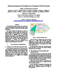
Figure 1.7: The CMS tracker.
The layout of the tracker is shown in figure 1.7. The central three layers are based on silicon pixel detectors. Surrounding this is the inner barrel, consisting of four layers of microstrip detectors, and the outer barrel, consisting of six layers. At each end of the cylinder are the pixel forward detector (2 layers, pixel), the inner disk (3 layers, microstrip) and the endcaps (9 layers). The original proposal had been to use microstrip gas chambers (MSGCs) for the outer layers of the tracker, but a review in December 1999 decided to move to an all-silicon design as this was just as viable and allowed more effort to be concentrated onto a smaller set of problems [7].
22
Introduction Pixel Detectors The pixel detectors are located close to the interaction point, where the occupancies are highest, in three barrel-layers and two end-layers. Each pixel measures 150 x 150 µm, and by using charge sharing between pixels to interpolate the track positions, will provide a spatial resolution of about 10 µm in the r-φ direction and about 20 µm in the z direction [6]. The pixel detector will confirm or reject track segments proposed by the surrounding tracker layers. Microstrip Detectors The microstrip detectors are arranged in 10 layers around the pixel detectors. Their pitch varies from 80 µm in the inner layer to 205 µm in the outer layer. Typical spatial resolutions (for a 100 µm pitch detector) are 34 µm in r-φ and 320 µm in the z direction [6]. One of the prototype detector hybrid modules from the microstrip tracker is shown in figure 1.8. It consists of two microstrip detectors, bonded together at the centre. A pitch adaptor connects one end of the detector to the APV readout chips. There is space for six APV chips; each reading out 128 of the 768 detector strips, although in the prototype only three are mounted, and only half of the detector is read out. A kapton cable connects the outputs of the APVs to the opto-hybrid, where the signals are driven via optical fibres to the counting room.
Figure 1.8: A prototype microstrip detector module from the tracker.
23
Introduction
1.3.3 The Electronic Calorimeter (ECAL) The electromagnetic calorimeter (ECAL) will consist of more than 80 000 lead tungstate (PbWO4) crystals (see figure 1.9). Lead tungstate is extremely dense (more than eight times denser than water), and the whole collection of crystals will weigh more than 90 tonnes [8]. Lead tungstate has a very short radiation length of 0.89 cm, allowing a very compact detector, and a small Moliere radius of 2.19 cm, allowing a fine granularity. It has an interaction length of 22.4 cm, and each crystal has a length of 22 cm [8], so hadrons will on average only interact once in the ECAL.
Figure 1.9: An ECAL crystal.
Particles are detected in the ECAL by the scintillation light they produce in the crystals. This is measured by avalanche photodiodes in the barrel section, and by vacuum phototriodes in the endcap regions, where the neutron flux is higher, and the photodiodes would suffer unacceptably high radiation damage. Vacuum phototriodes cannot be used in the barrel region due to the orientation of the magnetic field.
24
Introduction
1.3.4 The Hadronic Calorimeter (HCAL) The combined calorimeter system of CMS will measure the directions and energies of quarks, gluons, and neutrinos indirectly by measuring the direction and energy of particle jets and of the missing transverse energy [9]. Both the barrel and the endcap of the HCAL (see figure 1.10) will experience the 4 Tesla magnetic field of the CMS solenoid, and are therefore constructed from brass and stainless steel, which are non-magnetic. The central hadronic calorimeter consists of 4 mm thick plastic scintillator tiles inserted between copper absorber plates (5 cm thick in the barrel and 8 cm thick in the endcaps). The scintillator tiles are read out using wavelength-shifting plastic fibres. An additional layer of scintillator tiles is located outside of the solenoid to ensure adequate sampling depth for the whole |η| < 3 region. This is known as the outer hadronic calorimeter. The thickness of the HCAL system varies from 5.15 interaction lengths at η = 0 up to 5.82 interaction lengths [9].
Figure 1.10: An assembled half-barrel of the HCAL.
25
Introduction The HCAL also includes the forward calorimeter, located 6 m downstream from the HCAL endcaps, and extending the hermeticity of the hadronic calorimeter up to |η| < 5. It is constructed from quartz fibres embedded in a copper absorber matrix, and is necessary for an accurate measurement of missing transverse energy, and for forward jet detection.
1.3.5 The Muon Detectors There are three different types of detector used for muons: Resistive Parallel Plate Chambers (RPCs), Drift Tubes (DTs), and Cathode Strip Chambers (CSCs). Together they measure the transverse momentum of the muons with an accuracy of better than 4 % up to |η| < 2, for muons with a typical energy of 100 GeV [10]. Drift Tubes The drift tubes are located in the central barrel region of the detector, where the magnetic field is guided and almost fully trapped by the iron plates of the magnet yoke. They are located in four layers, or stations; two on the inner and outer face of the iron yoke, and two in slots inside it. The redundancy provided by four stations of twelve planes each means it is possible to cope with inefficiencies from dead zones caused by supporting ribs and longitudinal space caused by the joins between the rings of the CMS detector. Al plate
wire
I-beam
Figure 1.11: A Muon drift tube.
26
Introduction A diagram of a drift tube is shown in figure 1.11. It consists of parallel aluminium plates separated by aluminium I-beams, with a wire stretched along the centre. When an ionising particle passes through the tube, it liberates electrons, which then drift along the electric field lines towards the positively charged wire. The time taken for the ionisation electrons to drift to the wire is measured to within an accuracy of 1 ns, and as the drift velocity of the electrons is known, this gives a good measure of the distance of the original particle from the wire. Cathode Strip Chambers The cathode strip chambers (CSCs) are located in the endcap regions of the detector, where the magnetic field is vertical and contained within the iron yoke disks. There are four layers of CSCs sandwiched between the iron disks of the return yoke.
Figure 1.12: A Muon cathode strip chamber.
A CSC (see figure 1.12) consists of cathode planes segmented into strips, and interleaved with wires running perpendicular to the strips. A passing particle ionises atoms, and the freed electrons are collected by the wires, while the positive ions drift to the strips. This gives two coordinates, the wires measuring the radial coordinate, while the strips measure φ. The close spacing of the wires make the CSC a fast detector, particularly suitable for triggering.
27
Introduction Resistive Parallel Plate Chambers The Resistive Plate Chambers (RPCs) are used in both the barrel and the endcap regions of the detector, and are used to provide an additional complementary trigger. They will cover approximately the same area as the DTs and CSCs, but will provide a faster timing signal and have a different sensitivity to background.
Figure 1.13: A Muon resistive plate chamber.
An RPC is shown in figure 1.13. It consists of two parallel plates of highresistivity plastic material, separating a thin gap filled with gas. A passing ionising particle releases electrons, which accelerate towards the positively charged side of the chamber in an avalanche. The plastic is transparent to these electrical signals, which are then picked up by external metallic strips. The signals from each of the three types of muon detectors proceed in parallel to the trigger logic. Every muon with enough energy to penetrate the detector material should traverse at least three of the muon stations.
1.3.6 The Trigger In normal operation, the global trigger processor receives data from the calorimeters and the muon chambers. It can also use special signals for set-up, synchronisation, calibration and testing purposes. It contains logic for processing up to 128 different trigger algorithms in parallel, the results being delivered as a
28
Introduction 128-bit word, with one bit per algorithm. This can be compared with a predefined input word that selects which particular triggers are of interest for the run.
Figure 1.14: The CMS level-1 global trigger. (Adapted from ref [11])
The level-1 accept trigger decision (L1A), along with the 40.08 MHz LHC machine clock, and other signals, such as bunch-crossing reset are distributed to the detector by the TTC system. The data for each 25 ns bunch-crossing period are stored in the detector front-end until the trigger decision is known. This period, known as the trigger latency, will be about 3 µs.
1.4
Summary The CMS detector and its readout system need to process huge volumes of
data, and reduce it to a manageable amount before it can be stored and properly analysed. The LHC, at its full luminosity, will generate 20 interactions with a significant transverse energy for every bunch crossing, at a rate of 40.08 MHz. The first level trigger will reduce this to a rate of up to 100 kHz, with the raw data for each event being about 1 Mbyte. This means that the readout system still needs to process about 100 Gbyte of data every second. The tracker consists of about 10 million detector channels, and is expected to generate up to 70 % of the final data volume at CMS. These data rates are orders of magnitude higher than in any previous experiment and demand state-of-the-art technology as well as massively parallel processing if the experiment is to be successful.
29
Chapter 2: Field Programmable Devices All digital logic circuits are made up of simple building blocks known as logic gates, which are in turn made of transistors. Two main technologies exist, known as transistor-transistor logic (TTL) and complementary metal oxide semiconductor (CMOS).
2.1
Digital Logic The older of the two, TTL is made of bipolar transistors, which are
sandwiches of n- and p-type semiconductor material in either npn or pnp configurations (see figure 2.1). The transistor consists of two p-n junctions, with the thin central section connected to the base terminal, and the two ends connected Base
Emitter
N
Base
P
N
Collector
Emitter
P
N
P
Collector
Characteristic Curves for 2N3904 (NPN) IB = 80 µA
C B
IC (A)
B
C
E
E IB = 10 µA VCE (V)
Figure 2.1: Bipolar transistors (npn and pnp) and their symbols.
to the collector and the emitter. An npn transistor conducts current when its base is pulled high, and a pnp transistor conducts when its base is low. Bipolar transistors are current-amplifying devices: the amount of current flowing into the base controls the amount of current flowing in the collector circuit, but they can also be used in voltage amplification circuits. Bipolar transistors can operate at speeds in excess of a gigahertz, and can be designed to handle large currents up to several amps, but they have a relatively low input impedance of up to about 1 kΩ, and so are not suitable for applications requiring high circuit impedance.
30
Field Programmable Devices Field effect transistors exist in two main types, Junction Field Effect Transistor (JFET) and Metal Oxide Semiconductor FET (MOSFET). In both types, current flows along a semiconductor channel (n-type or p-type) between the source at one end and the drain at the other. In a JFET, the gate is of the opposite type of semiconductor to the channel, creating a p-n junction (see figure 2.2). A DC voltage is connected to the gate so that the junction is normally reversebiased, although under certain conditions a small current can flow during part of the signal cycle.
Gate
Source
p n+
Drain
Source
Gate
n-
n n+
pSubstrate Terminal
Bulk
p+
p+
nSubstrate Terminal
Characteristic Curves for a Typical JFET VG = 2 V
D ID (mA)
D G
Drain p-
G VG = 1 V
S
S VG = 0 V VDS (V)
Figure 2.2: JFET transistors (n-channel and p-channel) and their symbols.
In MOSFETs the gate electrode is a piece of metal, separated from the semiconductor by a layer of oxidised silicon (see figure 2.3). This gate oxide acts as a dielectric and electrically insulates the gate from the junction. Because of this, the MOSFET has a very high input impedance of several megohms, and virtually no current flows during any part of the input cycle. However, the oxide layer is very thin, and is susceptible to damage from electrostatic discharge, so special precautions are necessary when handling MOS devices. A p-channel FET conducts when the gate voltage is low, and an n-channel FET conducts when the gate voltage is high.
31
Field Programmable Devices
Gate Source
Gate Drain
Metal
SiO2
n+
n+
p-
D
SiO2
p+
D
G
D B
G
S
p+
Substrate Terminal (B)
D B
Drain
Metal
n-
Bulk
Substrate Terminal (B)
G
Source
S
G
S
S
Figure 2.3: MOSFET transistors (n-channel and p-channel) and their symbols.
The dominant semiconductor technology is CMOS, which uses a combination of both n-channel and p-channel MOSFETS. The main advantage is its very low static power consumption; power is only dissipated when the circuit switches, allowing many gates to be integrated into each IC, resulting in higher performance than is possible with bipolar technology.
2.1.1 Combinatorial Logic A CMOS inverter can be built with only two complementary MOSFET transistors (see figure 2.4). When the input voltage is high, the output is connected
VDD S’ A
Q
A
Q
S GND S’ A
Q
A
Q S
Figure 2.4: A CMOS inverter and transmission gate, and their symbols.
32
Field Programmable Devices to ground, and when it is low, the output is connected to the drain voltage, VDD (typically 1.8, 2.5, 3.3 or 5V). A transmission gate is used like a switch; when the input S is high (and S' is low), the input A appears at the output Q, and when S is low (and S' is high), the output is in a high impedance state, effectively disconnected. VDD
VDD
A
Q
A
B
B
Q
GND
GND
Figure 2.5: CMOS NAND and NOR gates and their symbols.
Two other combinatorial logic gates, the NAND and the NOR, are shown in figure 2.5, along with their truth tables in table 2.1. Other logic gates, such as AND and OR gates can be easily constructed by following the output of a NAND or NOR gate with an inverter. A 0 0 1 1
B 0 1 0 1
Q 1 1 1 0
A 0 0 1 1
B 0 1 0 1
Table 2.1: Truth tables for NAND and NOR gates.
33
Q 1 0 0 0
Field Programmable Devices
2.1.2 Sequential Logic In combinatorial logic circuits, the output is a function of only the current inputs. More complex circuits use sequential logic, with memory that is generated by feeding the output of a logic-block back in to the inputs. The output of a sequential logic circuit is a function not only of the current inputs, but also of past inputs. The simplest sequential logic block is the latch (see figure 2.6). When the clock input is high, the output follows the data input, but when the clock input is low, the output retains its current level no matter what appears on the data input. This is known as a level-triggered, or transparent, latch because it is triggered by the level of the clock input. However, most sequential logic is edge-triggered, meaning that the output only takes on the value at the input at the rising edge of the clock. This is achieved using two transparent latches in series, the second triggered by the inverse of the clock, producing what is known as a D-type flipflop (see figure 2.6). CLKN
D
Q
CLKN
CLK
CLKP
CLKP
D
D
Q
D
CLK
Q
Q
CLK
CLKP
CLK
CLKN
D
Q
D
CLK
Q
CLK
Figure 2.6: CMOS transparent latch and flip-flop and their symbols.
2.2
Programmable Logic When custom logic devices are needed in a system, there are a number of
different options available. Simple circuits can often be built out of discrete logic components, but many systems are more complex, consisting of the equivalent of tens of millions of logic gates, and this quickly becomes unfeasible. Another
34
Field Programmable Devices option is to use a microprocessor, which offers great flexibility and is functionally very versatile, but due to its inherently serialised processing, for many tasks it is just too slow, when compared to the hugely parallel processing available in a dedicated logic circuit. Application-specific integrated circuits (ASICs) are made up of successive layers, etched directly onto a silicon wafer using a photographic mask, and offer the highest level of complexity and speed. In full-custom ASICs, all mask layers are customised, and designing a new IC takes a huge amount of time and effort, as each individual transistor needs to be specified. In a standard-cell-based ASIC all layers are also customised, but a library of standard cells are available for higherlevel functions, reducing the design effort to some extent. Another type of ASIC technology is the mask-programmable gate array (MPGA), which consists of an array of standard blocks, with only the interconnect layers being customised [12]. This reduces the manufacturing lead-time, but any design changes still require a complete new manufacturing run. Field programmable logic devices have no custom mask layers or custom logic cells; they are programmed by the user. They have the advantage over custom-designed ASICs that the design and verification process is much faster, and (in technologies which are not one-time programmable) the configuration can be updated at a later time to fix errors, or simply to upgrade the firmware. For small to medium volumes they are also much cheaper. The disadvantage is that all the programming logic takes up space in the chip, leaving less space for the actual design. In a 0.18µm process an FPGA typically holds 1500 gates/mm2 compared to 60 000 gates/mm2 for an ASIC, and runs at a maximum clock speed of 100 MHz, compared to 600 MHz in an ASIC. However, the density of these devices is increasing rapidly, and in many situations it is the speed of the input/output logic that limits the amount of processing that can be done, so FPGAs are becoming powerful enough to replace ASICs in more and more situations.
35
Field Programmable Devices
2.3
History of Programmable Logic
2.3.1 The PROM The first type of user-programmable chip that could implement logic circuits was the PROM [13] (see figure 2.7). The n address lines represent the input to the logic function, the decoder translates each of the 2n possible combinations to a logic signal on one of 2n lines, and the m data lines are different functions of the inputs. Filling the memory appropriately allows any arbitrary logic function to be generated [12]. The 2n lines generated by the decoder are known as product terms, and are logical ANDs of the input lines (or their inverses). If each product term is a function of all of the input lines (or their inverses), as is the case here, then they are known more specifically as minterms, and each will be active for only one possible input combination. Each function is simply a logical OR of all the minterms for which the corresponding bit in the memory is high. This method of representing a logic function is known as a sum of products (SOP).
2n
1 2
Decoder
Address
PROM
n
1 2
Data
m
Figure 2.7: Memory used as programmable logic. (Adapted from ref [13])
36
Field Programmable Devices
2.3.2 The PLA and PAL Most logic functions require relatively few product terms, while a PROM contains a full decoder for its address inputs (generating all 2n possible minterms for the n inputs). This makes it an inefficient architecture for implementing logic circuits, as a lot of the logic is never used. A Programmable Logic Array (PLA) is based on the same principle as the PROM device, but without the full decoding of the input variables (see figure 2.8). An array of programmable AND gates provide the product terms, and an array of programmable OR gates provide the sum of products. The number of product terms available is less than the total number of minterms (in this case 2 instead of 4), but most logic functions can be rewritten to use fewer product terms (e.g. using Karnaugh maps) and made to fit. A AND Array B _ A.B _ A.B _ _ B B A A OR Array _ _ A.B+A.B Figure 2.8: A very small PLA. (Adapted from ref [13])
The two levels of configurable logic in a PLA make it relatively expensive to manufacture, and also affect the speed performance [12]. To overcome this, Programmable Array Logic (PAL®) devices were developed. They are similar to PLAs; with the OR array being fixed instead of programmable, and a number of improvements. The outputs of the OR gates are fed back to the inputs of the AND array, allowing a reduction in the number of terms in some functions at the expense of speed. At the outputs of the OR gates there are flip-flops, also with 37
Field Programmable Devices their outputs fed back to the inputs of the AND array, allowing more complex systems to be built, such as state machines. The I/O pins are programmable, with tri-state outputs, allowing them to be used for input, output, or bi-directional signals.
2.3.3 The CPLD Small programmable devices, including PLAs and PALs, are known collectively as Simple Programmable Logic Devices (SPLDs). As technology advanced, the capacity of SPLDs grew; but with these architectures, the structure of the logic planes grows very quickly as the number of inputs is increased, so the logic becomes less efficiently used. To get around this, Complex Programmable Logic Devices (CPLDs) were developed. These are effectively arrays of PAL-like blocks (known as macrocells) connected together with a programmable interconnect (see figure 2.9).
I/O Control Block
LAB
LAB
Programmable Programmable Interconnect Interconnect
LAB
LAB
LAB
Local Array
I/OControl ControlBlock Block I/O
LAB
macrocells
Logic Array Block
Figure 2.9: Architecture of a CPLD. (Adapted from ref [13])
Blocks of 8 to 16 macrocells are grouped together with other logic into function blocks, or Logic Array Blocks (LABs), with the macrocells within each function block usually being fully interconnected [13]. Often the function blocks themselves will only be partially interconnected, as it makes the manufacturing process cheaper, but it means that complex designs will be harder to route, and design changes may force the pin layout to be changed. It also has the effect that
38
Field Programmable Devices the delays between the function blocks are not fixed, whereas with full interconnect the delays are fixed and predictable. CPLDs are generally CMOS devices, and use non-volatile memory cells (usually EEPROM or FLASH) to define their functionality. Typically, they are insystem programmable (ISP), meaning they can be programmed in-circuit, as opposed to needing to be plugged into a special CPLD-programming unit.
2.3.4 The FPGA The architecture of CPLDs makes it difficult to increase the capacity beyond the equivalent of about 50 SPLD devices. The highest capacity devices, Field Programmable Gate Arrays (FPGAs), are based on a different architecture, similar to MPGAs. They are made up of an array of up to about 100 000 configurable logic blocks (CLBs), surrounded by programmable I/O blocks, and connected by a programmable interconnect network (see figure 2.10). The blocks are not fully interconnected, but sophisticated software is used to route the logic.
IOB
IOB I/O Block
IOB
CLB
CLB Configurable Logic Block Switch Matrix
Figure 2.10: Architecture of an FPGA. (Adapted from ref [13])
FPGAs can be either coarse-grained or fine-grained. Coarse-grained FPGAs contain large logic blocks containing two or more look-up tables, two or more flip-flops, and other logic such as multiplexers and fast-carry logic. Fine-grained FPGAs, on the other hand, contain a large number of simple logic blocks containing either a 2-input logic function or 4-to-1 multiplexer, and a flip-flop. They make more efficient use of the active components, but require greater
39
Field Programmable Devices routing resources, and are generally slower and less dense. An example (from a Plessey device) is shown in figure 2.11.
Latch Clk Mux 8x2
D
Interconnect Lines
Q
Configuration RAM
Figure 2.11: Example of a fine-grained logic cell. (Adapted from ref [13])
2.4
Memory Technology
2.4.1 Fuses and Antifuses Field programmable devices are programmed after the manufacturing process, and the configuration has to be stored in some form of memory. There are several technologies available for this, each with its own advantages and disadvantages. The original technology used was fuse technology. A metal link creates a normally closed connection, and the device is programmed by passing a relatively large current through the fuse, melting it and opening the connection.
~20 nm
Poly-Si
metal 2 SiO2
ONO dielectric
clk, data_bx_id => data_bx_id, data_evt_stat => data_evt_stat, data_evt_ty => data_evt_ty, data_lv1_id => data_lv1_id, data_source_id => data_source_id, wr_start => wr_start, rd_data => rd_data, reset => reset, rd_start => rd_start, data_out => header_in, data_out_sel => data_out_sel,
117
Common Data Format Implementation
rd_en wr_ready wr_data wr_en data_evt_lgth rd_ready full empty data_in_en linkbusy rd_stop data_in
=> => => => => => => => => => => =>
rd_en, wr_ready, wr_data, wr_en, data_evt_lgth, rd_ready, full, empty, data_in_en, linkfull, rd_stop, data_in
); fifo1 : fifo GENERIC MAP ( addr_bits => fifo_addr_bits ) PORT MAP ( clk => clk, rd_en => rd_en, wr_en => wr_en, wr_data => wr_data, reset => reset, rd_data => rd_data, full => full, empty => empty ); mux1 : mux PORT MAP ( clk => clk, data_in => data_in, header_in => header_in, header_sel => data_out_sel, reset => reset, ctrl => ctrl, data_en => data_out_en, data_out => data_out, data_in_en => data_in_en ); END fed_data_format;
A.2
builder.vhd
-- hds header_start --- VHDL Architecture FED_DATA_FORMAT.builder.untitled --- Created: -by - corrinep.UNKNOWN (SIMPC) -at - 13:25:28 11/12/2001 --- Generated by Mentor Graphics' HDL Designer(TM) 2001.5 (Build 170) --- hds header_end LIBRARY ieee; USE ieee.std_logic_1164.ALL; ENTITY builder IS PORT(
118
Common Data Format Implementation
clk data_bx_id data_evt_stat data_evt_ty data_lv1_id data_source_id wr_start rd_data reset rd_start data_out data_out_sel rd_en wr_ready wr_data wr_en data_evt_lgth rd_ready full empty data_in_en linkbusy rd_stop data_in
: : : : : : : : : : : : : : : : : : : : : : : :
IN IN IN IN IN IN IN IN IN IN OUT OUT OUT OUT OUT OUT IN OUT IN IN IN IN IN IN
std_logic; std_logic_vector std_logic_vector std_logic_vector std_logic_vector std_logic_vector std_logic; std_logic_vector std_logic; std_logic; std_logic_vector std_logic_vector std_logic; std_logic; std_logic_vector std_logic; std_logic_vector std_logic; std_logic; std_logic; std_logic; std_logic; std_logic; std_logic_vector
(11 DOWNTO 0); (7 DOWNTO 0); (3 DOWNTO 0); (23 DOWNTO 0); (11 DOWNTO 0); (63 DOWNTO 0);
(63 DOWNTO 0); (1 DOWNTO 0);
(63 DOWNTO 0); (23 DOWNTO 0);
(63 DOWNTO 0)
); -- Declarations END builder ; -- hds interface_end LIBRARY ieee; USE ieee.std_logic_arith.ALL; USE ieee.std_logic_unsigned.ALL; LIBRARY FED_DATA_FORMAT; --USE FED_DATA_FORMAT.PCK_CRC16_D64_CCITT.ALL; USE FED_DATA_FORMAT.PCK_CRC16_D64_X25.ALL; --USE FED_DATA_FORMAT.PCK_CRC16_D64_SIMPLE.ALL; ARCHITECTURE builder OF builder IS -- Areas CONSTANT CONSTANT CONSTANT CONSTANT CONSTANT CONSTANT CONSTANT
in header r_boe: r_evt_ty: r_lv1_id: r_bx_id: r_src_id: r_fov: r_last:
-- Areas CONSTANT CONSTANT CONSTANT CONSTANT
in trailer word r_eoe: std_logic_vector(63 r_evt_lgth: std_logic_vector(55 r_crc: std_logic_vector(31 r_evt_stat: std_logic_vector(11
-- Constants CONSTANT c_boe1: CONSTANT c_boe2: CONSTANT c_fov: CONSTANT c_last: CONSTANT c_nlast: CONSTANT c_eoe:
word, value is ignored, just interested in range std_logic_vector(63 DOWNTO 60) := (OTHERS => '0'); std_logic_vector(59 DOWNTO 56) := (OTHERS => '0'); std_logic_vector(55 DOWNTO 32) := (OTHERS => '0'); std_logic_vector(31 DOWNTO 20) := (OTHERS => '0'); std_logic_vector(19 DOWNTO 8) := (OTHERS => '0'); std_logic_vector( 7 DOWNTO 4) := (OTHERS => '0'); std_logic_vector( 3 DOWNTO 3) := (OTHERS => '0');
std_logic_vector std_logic_vector std_logic_vector std_logic_vector std_logic_vector std_logic_vector
:= := := := := :=
DOWNTO DOWNTO DOWNTO DOWNTO
"0001"; "0010"; "0001"; "1"; "0"; "1001";
119
60) 32) 16) 4)
-------
:= := := :=
(OTHERS (OTHERS (OTHERS (OTHERS
=> => => =>
'0'); '0'); '0'); '0');
Beginning of event, first word Beginning of event, second word Format version Last header word Not last header word End of event
Common Data Format Implementation
CONSTANT CRC_INIT: std_logic_vector := "1111111111111111"; -- Initial value for CRC calculation SIGNAL save_evt_stat: std_logic_vector(data_evt_stat'range); SIGNAL save_evt_lgth: std_logic_vector(data_evt_lgth'range); TYPE wr_type IS (idle, writing); SIGNAL wr_state: wr_type; TYPE rd_type IS (idle, headerstart, header, datastart, data); SIGNAL rd_state: rd_type; BEGIN -- builds header and trailer words and writes them to fifo proc_wr: PROCESS(clk, reset) BEGIN IF (reset = '0') THEN -- reset signals to default: wr_state addr_bits ) PORT MAP( clk => clk, rd_add => rd_add, rd_en => rd_en, wr_add => wr_add, wr_data => wr_data, wr_en => wr_en, rd_data => rd_data ); rd_add '0'); BEGIN mux: PROCESS(clk, reset)
125
Common Data Format Implementation
BEGIN IF (reset = '0') THEN data_en 9, length_at_start => true ) PORT MAP ( clk => clk, data_bx_id => data_bx_id, data_evt_lgth => data_evt_lgth, data_evt_stat => data_evt_stat, data_evt_ty => data_evt_ty, data_in => data_in, data_in_en => data_in_en, data_lv1_id => data_lv1_id, data_source_id => data_source_id, linkfull => linkfull, rd_start => rd_start, rd_stop => rd_stop, reset => reset, wr_start => wr_start, ctrl => ctrl, data_out => data_out, data_out_en => data_out_en, rd_ready => rd_ready, wr_ready => wr_ready ); I1 : data_format_tester PORT MAP ( ctrl => ctrl, data_out => data_out, data_out_en => data_out_en,
134
Common Data Format Verification Code
rd_ready wr_ready clk data_bx_id data_evt_lgth data_evt_stat data_evt_ty data_in data_in_en data_lv1_id data_source_id linkfull rd_start rd_stop reset wr_start
=> => => => => => => => => => => => => => => =>
rd_ready, wr_ready, clk, data_bx_id, data_evt_lgth, data_evt_stat, data_evt_ty, data_in, data_in_en, data_lv1_id, data_source_id, linkfull, rd_start, rd_stop, reset, wr_start
); END testbench;
B.2
tester.vhd
-- hds header_start --- VHDL Architecture FED_DATA_FORMAT.data_format_tester.untitled --- Created: -by - corrinep.UNKNOWN (EMLYN) -at - 15:59:19 10/03/02 --- Generated by Mentor Graphics' HDL Designer(TM) 2002.1a (Build 22) --- hds header_end LIBRARY ieee; USE ieee.std_logic_1164.all; USE ieee.std_logic_arith.all; ENTITY data_format_tester IS PORT( ctrl : IN data_out : IN data_out_en : IN rd_ready : IN wr_ready : IN clk : OUT data_bx_id : OUT data_evt_lgth : OUT data_evt_stat : OUT data_evt_ty : OUT data_in : OUT data_in_en : OUT data_lv1_id : OUT data_source_id : OUT linkfull : OUT rd_start : OUT rd_stop : OUT reset : OUT wr_start : OUT );
std_logic; std_logic_vector std_logic; std_logic; std_logic; std_logic; std_logic_vector std_logic_vector std_logic_vector std_logic_vector std_logic_vector std_logic; std_logic_vector std_logic_vector std_logic; std_logic; std_logic; std_logic; std_logic
135
(63 DOWNTO 0);
(11 DOWNTO 0); (23 DOWNTO 0); (7 DOWNTO 0); (3 DOWNTO 0); (63 DOWNTO 0); (23 DOWNTO 0); (11 DOWNTO 0);
Common Data Format Verification Code
-- Declarations END data_format_tester ; -- hds interface_end USE std.textio.ALL; LIBRARY ieee; USE ieee.std_logic_arith.ALL; USE ieee.std_logic_unsigned.ALL; LIBRARY FED_DATA_FORMAT; USE FED_DATA_FORMAT.RNG.ALL; ARCHITECTURE tester OF data_format_tester IS FUNCTION chr(sl: std_logic) RETURN character is VARIABLE c: character; BEGIN CASE sl IS WHEN 'U' => c:= 'U'; WHEN 'X' => c:= 'X'; WHEN '0' => c:= '0'; WHEN '1' => c:= '1'; WHEN 'Z' => c:= 'Z'; WHEN 'W' => c:= 'W'; WHEN 'L' => c:= 'L'; WHEN 'H' => c:= 'H'; WHEN '-' => c:= '-'; WHEN OTHERS => c := '?'; END CASE; RETURN c; END chr; FUNCTION str(sl: std_logic) RETURN string IS VARIABLE s: string(1 TO 1); BEGIN s(1) := chr(sl); RETURN s; END str; FUNCTION str(slv: std_logic_vector) RETURN string IS VARIABLE s: string(1 TO slv'length); VARIABLE i, j: integer; BEGIN j := 1; FOR i IN slv'RANGE LOOP s(j) := chr(slv(i)); j := j + 1; END LOOP; RETURN s; END str; PROCEDURE RndSlv(rng: INOUT random; ret: OUT std_logic_vector) IS VARIABLE r: std_logic_vector(63 DOWNTO 0); BEGIN GenRnd(rng); r(63 DOWNTO 48) := conv_std_logic_vector(integer(rng.rnd), 16);
136
Common Data Format Verification Code
GenRnd(rng); r(47 DOWNTO 32) := conv_std_logic_vector(integer(rng.rnd), 16); GenRnd(rng); r(31 DOWNTO 16) := conv_std_logic_vector(integer(rng.rnd), 16); GenRnd(rng); r(15 DOWNTO 0) := conv_std_logic_vector(integer(rng.rnd), 16); ret := r; END RndSlv; CONSTANT half_period: time := 12500 ps; TYPE state_type IS (idle, pause, data); TYPE arr IS ARRAY(NATURAL RANGE) OF NATURAL; CONSTANT lengths: arr := (24, 10, 15, 0, 70, 1); FILE output: text IS OUT "tester.txt"; SIGNAL clk_int, trigger: std_logic; BEGIN clk cm_width = 16; */ /* p_cm->cm_poly = 0x8005L; */ /* p_cm->cm_init = 0L; */ /* p_cm->cm_refin = TRUE; */ /* p_cm->cm_refot = TRUE; */ /* p_cm->cm_xorot = 0L; */ /* Note: Poly is specified without its top bit (18005 becomes 8005). */ /* Note: Width is one bit less than the raw poly width. */ /* */ /* Step 3: Initialize the instance with a call cm_ini(p_cm); */ /* */ /* Step 4: Process zero or more message bytes by placing zero or more */ /* successive calls to cm_nxt. Example: cm_nxt(p_cm,ch); */ /* */ /* Step 5: Extract the CRC value at any time by calling crc = cm_crc(p_cm); */ /* If the CRC is a 16-bit value, it will be in the bottom 16 bits. */ /* */ /******************************************************************************/ /* */ /* Design Notes */ /* -----------*/ /* PORTABILITY: This package has been coded very conservatively so that */ /* it will run on as many machines as possible. For example, all external */ /* identifiers have been restricted to 6 characters and all internal ones to */ /* 8 characters. The prefix cm (for Crc Model) is used as an attempt to avoid */ /* namespace collisions. This package is endian independent. */ /* */ /* EFFICIENCY: This package (and its interface) is not designed for */ /* speed. The purpose of this package is to act as a well-defined reference */ /* model for the specification of CRC algorithms. If you want speed, cook up */ /* a specific table-driven implementation as described in the document cited */ /* above. This package is designed for validation only; if you have found or */
142
Common Data Format Verification Code
/* implemented a CRC algorithm and wish to describe it as a set of parameters */ /* to the Rocksoft^tm Model CRC Algorithm, your CRC algorithm implementation */ /* should behave identically to this package under those parameters. */ /* */ /******************************************************************************/ /* The following #ifndef encloses this entire */ /* header file, rendering it indempotent. */ #ifndef CM_DONE #define CM_DONE /******************************************************************************/ /* The following definitions are extracted from my style header file which */ /* would be cumbersome to distribute with this package. The DONE_STYLE is the */ /* idempotence symbol used in my style header file. */ #ifndef DONE_STYLE typedef unsigned long ulong; typedef unsigned bool; typedef unsigned char * p_ubyte_; #ifndef TRUE #define FALSE 0 #define TRUE 1 #endif #endif /******************************************************************************/ /* CRC Model Abstract Type */ /* ----------------------- */ /* The following type stores the context of an executing instance of the */ /* model algorithm. Most of the fields are model parameters which must be */ /* set before the first initializing call to cm_ini. */ typedef struct { int cm_width; /* Parameter: Width in bits [8,32]. */ ulong cm_poly; /* Parameter: The algorithm's polynomial. */ ulong cm_init; /* Parameter: Initial register value. */ bool cm_refin; /* Parameter: Reflect input bytes? */ bool cm_refot; /* Parameter: Reflect output CRC? */ ulong cm_xorot; /* Parameter: XOR this to output CRC. */ ulong cm_reg; /* Context: Context during execution. } cm_t; typedef cm_t *p_cm_t;
*/
/******************************************************************************/ /* Functions That Implement The Model */ /* ---------------------------------- */ /* The following functions animate the cm_t abstraction. */ void cm_ini(p_cm_t p_cm); /* Initializes the argument CRC model instance. */ /* All parameter fields must be set before calling this. */
143
Common Data Format Verification Code
void cm_nxt(p_cm_t p_cm,int ch); /* Processes a single message byte [0,255]. */ void cm_blk(p_cm_t p_cm,p_ubyte_ blk_adr,ulong blk_len); /* Processes a block of message bytes. */ ulong cm_crc(p_cm_t p_cm); /* Returns the CRC value for the message bytes processed so far. */ /******************************************************************************/ /* /* /* /*
Functions For Table Calculation */ ------------------------------- */ The following function can be used to calculate a CRC lookup table. It can also be used at run-time to create or check static tables.
ulong cm_tab(p_cm_t p_cm,int index); /* Returns the i'th entry for the lookup table for the specified algorithm. /* The function examines the fields cm_width, cm_poly, cm_refin, and the /* argument table index in the range [0,255] and returns the table entry in /* the bottom cm_width bytes of the return value.
*/ */
*/ */ */ */
/******************************************************************************/ /* End of the header file idempotence #ifndef */ #endif /******************************************************************************/ /* End of crcmodel.h */ /******************************************************************************/
B.5
crcmodel.c
/******************************************************************************/ /* Start of crcmodel.c */ /******************************************************************************/ /* */ /* Author : Ross Williams (
[email protected].). */ /* Date : 3 June 1993. */ /* Status : Public domain. */ /* */ /* Description : This is the implementation (.c) file for the reference */ /* implementation of the Rocksoft^tm Model CRC Algorithm. For more */ /* information on the Rocksoft^tm Model CRC Algorithm, see the document */ /* titled "A Painless Guide to CRC Error Detection Algorithms" by Ross */ /* Williams (
[email protected].). This document is likely to be in */ /* "ftp.adelaide.edu.au/pub/rocksoft". */ /* */ /* Note: Rocksoft is a trademark of Rocksoft Pty Ltd, Adelaide, Australia. */ /* */ /******************************************************************************/ /* */ /* Implementation Notes */ /* -------------------*/ /* To avoid inconsistencies, the specification of each function is not echoed */ /* here. See the header file for a description of these functions. */ /* This package is light on checking because I want to keep it short and */
144
Common Data Format Verification Code
/* simple and portable (i.e. it would be too messy to distribute my entire */ /* C culture (e.g. assertions package) with this package. */ /* */ /******************************************************************************/ #include "crcmodel.h" /******************************************************************************/ /* The following definitions make the code more readable. */ #define BITMASK(X) (1L =1; } return v; } /******************************************************************************/ static ulong widmask(p_cm_t p_cm) /* Returns a longword whose value is (2^p_cm->cm_width)-1. */ /* The trick is to do this portably (e.g. without doing cm_reg ^= (uch cm_width-8)); for (i=0; icm_reg & topbit) {
145
Common Data Format Verification Code
p_cm->cm_reg = (p_cm->cm_reg cm_poly; } else { p_cm->cm_reg cm_refot) { return p_cm->cm_xorot ^ reflect(p_cm->cm_reg,p_cm->cm_width); } else { return p_cm->cm_xorot ^ p_cm->cm_reg; } } /******************************************************************************/ ulong cm_tab(p_cm_t p_cm, int index) { int i; ulong r; ulong topbit = BITMASK(p_cm->cm_width-1); ulong inbyte = (ulong) index; if (p_cm->cm_refin) inbyte = reflect(inbyte,8); r = inbyte cm_width-8); for (i=0; i