Developing an Open Access Monitoring Device for Off-Grid Renewables Richard Blanchard#1, Matt Little*2 #
CREST, Loughborough University, United Kingdom
1
[email protected] *
Renewable Energy Innovation, Nottingham, United Kingdom
2
[email protected]
Abstract— Electricity access is a key driver for developing a modern society. The use of locally generated renewable energy can overcome limitations of expensive grid infrastructure. However, there are still barriers to access particularly for the rural poor in the global south. When individuals or communities invest in electricity provision it is important to know how well the system is performing. Commercial monitoring systems have been developed for large scale renewable energy systems. The cost of these can outweigh the cost of a small decentralised renewable energy system. This paper describes the development of a low cost data logger that is going to be used to monitor the system performance of small photovoltaic nano-grids in Kenya and Bangladesh. The device performs within the expected range for the current, voltage, temperature and irradiance sensors. Data from the data logger device is sent via GPRS to a website where it can be accessed as real time graphical displays and data files. Keywords— Remote monitoring, photovoltaics, nano-grid, GPRS, current, load, Bangladesh, Kenya
I. INTRODUCTION Access to modern energy services limits people’s ability to reach their potential. Around 1.3 billion people do not have access to electricity and 2.9 billion make use of traditional heating and cooking fuels [1]. These people are largely living in what can be described as rural locations. Electrification programmes have been developed in a number of countries to bring power to the people. However, even with ambitious schemes such as the Ravi Ghandi Rural Electrification Programme in India, people, especially the rural poor, are still going to be ‘under the cable’: that is unable to afford to connect to the grid. It is expected that by 2035 the number of people without access to electricity will not decline owing to population growth. There are alternatives to grid extension which include solar home systems (SHS) and micro-grids. SHS typically consist of a photovoltaic (PV) module, battery, lamps and a socket for powering a small device such as a mobile phone. SHS deployment has been successful in Bangladesh with funding supported through Grameen Shakti. However, SHS are limited in what they can do as they can only support low electrical loads. However, developing micro-grids is another option. Micro-grids are independent distributed generation networks that can be stand-alone or grid-tied. Their capacity can range
from a few kilowatts to megawatts as there is no absolute definition. At the smaller end of the scale the term nano-grids can be applied for the 1-4kW range. Nano-grids are proposed to support the space between SHS and micro-grids for small rural communities. The idea behind solar nano-grids (SONG) is not only to provide basic lighting and power for small electrical devices, but also to support some form of economic activity to help develop the community where such a SONG is installed. For example, this could be through milling grain, improving irrigation water pumping, egg incubators, refrigeration or hair clippers. A key feature of the nano-grid is that it will supply DC current. The principal reason for this was to keep costs down by avoiding the need for a DC-AC inverter. Furthermore, losses associated with DC-AC conversion will be reduced. In 2013 funding from UK Department for International Development and the Engineering Physical Sciences Research Council was approved to develop SONG1 systems in Kenya and Bangladesh. As part of the research two communities were identified in Kenya and two in Bangladesh. These have been widely consulted on their individual and community energy needs and SONG systems have been designed to meet these. However, as SONG is a new concept and it is important to learn how the systems perform against system models. Furthermore, these locations in Kenya and Bangladesh are remotely located making regular physical monitoring of the SONG systems difficult. Therefore, it was decided to employ remote monitoring technology to ascertain the efficacy of the SONG. Remote monitoring is not new even in renewable energy technologies such as wind farms or commercial anaerobic digesters where SCADA systems are used. But, these are often expensive costing £10,000s. This would not be applicable for SONG. Experience in developing remote access photovoltaic systems [2-5] and monitoring or rural biogas systems [6-7] led
1
The SONG partnership is led by Loughborough University UK, with United International University and Grameen Shakti Bangladesh, Intersave Kenya and the University of Oxford UK.
to the concept of developing a low cost device to monitor the SONG systems. The aim of this paper is to report on the development of an open access monitoring device for off-grid renewable energy systems. The objectives were to scope the system requirements, design and build the monitoring device as well as test the device prior to deployment in Kenya and Bangladesh. Costs, conclusions and future work are reported. II. METHODOLOGY The methodology is divided into three sections; system requirements, design and build, and testing. A. System requirements The development of the SONG remote monitoring device needed a requirements capture exercise to identify the whole and sub-systems that would be required. The first stage was to consider what was wanted from the device. The key features were to: Measure the electricity being produced from the photovoltaic modules Measure the irradiance Measure the battery state of charge Measure user loads Measure temperature of the modules and battery Have energy autonomy Store data Send data from the SONG system to an online website and database Report problems to the operator The original specifications were based on a 3kWp DC solar nano-grid supplied by project partner UIU, Bangladesh. The key components were: PV 3kWp Battery 36kWh Optimiser 3kW (input 48V DC, Output 220V DC Controller 3kW PWM charging, DR connection GSM connectivity for remote monitoring and controlling, Data logging Pre-paid DC energy meter: code programmable up to 500W
B. Design and build Having established the requirements and system conditions the unit specifications and sensors were identified as shown in Tables 1 and 2 TABLE 1 UNIT SPECIFICATIONS Parameter Input supply voltage Input current Internal battery Internal power supply ADC range ADC sensitivity Data sample rate
Value 6-60V DC 500mA 2200mAh 3.7V LiPo 5V nominal 6V max 15 bits 0.1mV 10Hz
TABLE 2 SENSORS Parameter Temp. Range Temp. accuracy Current sensor range Current sensor accuracy Voltage sensor (low) range Voltage sensor (high) range SD card size
Value -10oC to 100oC +/- 1oC 0-50A DC 2.5mA 0-60V DC 20-300V DC Up to 32GB
The device is based upon an open source microcontroller Linkit ONE Internet of Things base unit [8] This contains the SD card, GPRS module and GPS module. In addition, WiFi and Bluetooth can be used although they were not implemented for this project. The Linkit One device is connected to a bespoke PCB which contains 3 x analogue to digital converters, ADS1115 [9], the input power supply and the PV input voltage regulator. Any standard sized SIM card can be used with the adjacent SD card capable of storing up to 32GB. The battery, a LiPo 3.7V 2200mAh for back up, can run the device if input power is lost. The GPS sensor checks the location of the unit every 2 hours. If the unit location has differed by a distance of more than 50m then a text message is sent to SMS phone numbers of the operator. 1) Sensors Six current sensors were included with the device; these are based upon the ACS758 Allegro Hall effect current sensor [10]. The 50A uni-directional version has been used, namely ACS758-X050U. This was supplied with a regulated 5V supply voltage. The output is 0.6V + 60mV/A. The voltage sensors measure two voltage ranges; low 0-60V DC and high 0-300V DC. Two different sensors are used for these ranges. For the low voltage sensor, the unit specifications must be able to measure the DC voltage level up to 60V DC for the 48V battery bank. A potential divider is used which is calculated to give the correct conversion range. A 5.1V zener diode protects against potential over voltage.
To measure up to 60V DC, keeping within the 3.3V maximum input and using a 10k resistor as Ra, the potential divider will be comprised of Ra = 10k and Rb > 110k (where Vout = Vmax x (Ra/(Ra+Rb)). Hence 3.3 = 60 x (10/(10+110)). To allow for any higher voltages some headroom can be given. An Rb = 160k could give a voltage range up to 80V. The potential divider of 200k and 10k with 0.1% accuracy resisters are used for this function. For measuring higher voltages up to 300V DC is more challenging. Indeed, it can be dangerous and damage equipment. An isolation amplifier is used to provide up to 1000V isolation between the 300V signal and the ADC. This is performed using an ACPL-C870 [11-12]. A potential divider of 200k and 1k was used to give the input signal. 2) Temperature sensors A thermistor is used as part of the potential divider circuit with an accurate and stable reference voltage with low cost and good accuracy. A 10k thermistor is used to record the temperature. The thermistor is characterised as half of a potential divider, with a 10k precision resistor and a precision voltage regulator to supply the potential divider. The thermistor output needs to have the correct interpolation applied so that the temperature reading is accurate. Importantly, the thermistor needs to be thermally bonded to the unit under test.
Fig. 1 Remote monitoring device wiring schematic
3) Power supply The device is powered by a 2200mAh 3.7V LiPo battery. The charge is kept through a DC-DC converter power supply from the battery connection or via a solar PV backup. The DC-DC converter changes the input voltage of 6-60V DC down to the 5V used by the data logger. The solar PV backup uses a small PV module (1.5Wp) to top up the device battery.
A
4) Data monitoring Data is monitored via a web interface. This uses a bespoke version of ThingSpeak [13]. A specific data logger channel to present the outputs as graphs and record the data was setup[14].
B 5) Software and hardware License The work is released under a Creative Commons ByAttribution Share-Alike 4.0 (CC BY-SA 4.0) license [15]. Fig. 1 shows the schematic of the device and Fig 2 the completed prototype.
D
C
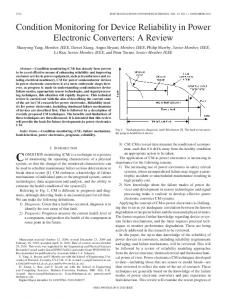
Fig.2 The prototype device. A=Data logger unit, B=Current sensors, C=Cable connectors, D=Packed back up 1.5Wp PV module
6) Embedded Software The embedded software has been written in C programming language. It is designed for upload to the LinkIt ONE unit via the Arduino IDE. An overview flow diagram is shown in Fig. 3 that indicates the steps in the data acquisition process for different sub-systems. Users are able to configure the monitoring device by a simple text configuration file which is described here. This can be edited and copied to the data logger SD card which sets the instructions by which the Linkit ONE operates. The data logger application has several configurable options. The details of those options and how the configuration file was written is described here. The configuration file is a small file on the root of the SD card.
THINGSPEAK_URL=agile-headland8076.herokuapp.com Setting names are all uppercase. Words in the name are separated with underscores. Setting values are either strings or numbers. All numbers are read as signed integers. Spaces on either side of the equals sign are ignored. For example: THINGSPEAK_URL=agile-headland8076.herokuapp.com and THINGSPEAK_URL = agile-headland8076.herokuapp.com will be treated identically. c) Comments Lines starting with a # are treated as comments. The entirety of the line will be ignored. Comments at the end of a line are not supported. e.g.: GPRS_APN=giffgaff.com # Some comment here is NOT valid and would result in the comment becoming part of the GPRS_APN setting. d) GPRS Settings There are three settings for GPRS connections shown in Table 3: TABLE 3 GPRS SETTINGS
Fig. 3 Software overview flow diagram
a) Filename & Location The configuration file MUST be stored on the root of the SD card under the name “Datalogger.settings.conf”. b) File Structure The configuration file has one setting per line. Each line has a setting name, an equals sign, and a setting value, e.g.:
Setting Name
Notes
GPRS_APN
The APN of the data provider
GPRS_USERNAME
The username for the data provider.
GPRS_PASSWORD
The password (sometimes not required).
These settings are readily available online for various data providers.
e) Data Storage Services The datalogger can upload data to remote online data storage services. Due to differences in how each service works, the settings for one service may differ from another. Currently the only supported service is Thingspeak, see table 4. Other services may be added in the future.
would result in a single average of 150 readings being taken and stored in RAM every 30 seconds. These readings would be uploaded every 180 seconds. This means that 6 averages would be uploaded every 180 seconds.
TABLE 4 CONFIG FILE UPLOAD SETTING
This data is averaged, stored in RAM and stored to SD card. Available configuration settings are: For example, settings of:
Setting Name
Notes
THINGSPEAK_URL
The URL of the thingspeak service
THINGSPEAK_API_KEY
The write API KEY for the thingspeak channel.
f) Telephone Numbers The datalogger can send text messages to inform users of its status. There are two sets of telephone numbers, see Table 5. General numbers are for basic status information. Maintenance numbers are for “alarm” type messages such as low battery warning. Up to four numbers may be specified for each set. Messages will be sent to all numbers in the set. TABLE 5 CONFIG FILE PHONE NUMBERS Setting Name
Notes
GENERAL_PHONE_NUMBER_1 GENERAL_PHONE_NUMBER_2 GENERAL_PHONE_NUMBER_3 GENERAL_PHONE_NUMBER_4
Up to 4 general numbers.
MAINTENANCE_PHONE_NUMBER_1 MAINTENANCE_PHONE_NUMBER_2 MAINTENANCE_PHONE_NUMBER_3 MAINTENANCE_PHONE_NUMBER_4
Up to 4 maintenance numbers.
h) Local Storage Settings Raw data is read 5 times per second.
STORAGE_AVERAGING_INTERVAL_SECS = 5 DATA_STORAGE_INTERVAL_SECS = 60 would result in a single average of 25 readings being taken and stored in RAM every 5 seconds. These readings would be stored to SD card every 60 seconds. This means that 12 averages would be stored every 60 seconds. Note: data storage and data upload are entirely independent functions. They both use the same raw data, but the uploading and storage are not dependent on each other to function. i) Battery Level Warning The battery level is checked every hour unless this is overridden in settings. If the battery level is equal to or less than the level set, the maintenance phones numbers are sent a warning message, see Table 6. TABLE 6 CONFIG FILE BATTERY WARNING
Exact phone number format will depend on country of use. Known formats: g) Upload Settings Raw data is read 5 times per second. This data is averaged, stored in RAM and uploaded. Available configuration settings are: For example, settings of UPLOAD_AVERAGING_INTERVAL_SECS = 30 DATA_UPLOAD_INTERVAL_SECS = 180
Setting Name
Notes
BATTERY_WARN_INTER VAL_MINUTES
Number of minutes between checking the battery (defaults to 60)
BATTERY_WARN_LEVEL
Battery warning level in percent (not including % sign). e.g to warn at 80% or below use BATTERY_WARN_LEV EL = 80
C. Testing In order to ascertain whether the device had been correctly constructed and the sensors were working within their design parameters the machine was tested using a Fluke voltage and
current generator. Sensors performed within expected tolerances. D. Economics The idea behind developing this data logger was to provide a tool to enable the performance of small scale renewable energy systems to be monitored. Data enables operators to check on whether the system is performing within expected parameters and also to indicate whether maintenance is needed. The data logging device has been developed from scratch. A budget of approximately £6,000 was allocated to building five of the devices. The learning meant that approximately £3,000 was spent developing the first prototype. Subsequently an additional five data loggers were developed for the remaining £3,000 budget. Clearly there is a learning curve from the initial £3,000 per unit cost for the first prototype to £600 per unit for the subsequent five devices. In the SONG project, a budget of £10,000 was assigned to each nano-grid that is being developed. Thus the cost of the data loggers being deployed is only 6% of the total SONG installation budget. Further iterations should in theory be cheaper. An interesting advantage for future developments is the data logger, communications and power management sub-systems can be attached to any sensors to transmit data to the operator website. III. CONCLUSIONS The development of low cost monitoring devices for remote renewable energy applications will help in the understanding of the performance of systems and how end-users make use of the energy available. The aim of the project, to develop such a remote monitoring device has been successfully achieved and has been described in this paper. The system requirements were developed into the design and subsequent construction of the data logger, communications, sensors and power subsystems. In addition, data can be sent to a website where it can be accessed and operators can be contacted by SMS text should problems arise with the SONG or the monitoring device. This has been rigorously tested prior to deployment. Interestingly, the data logger, communications platform and power sub-systems have the real potential to be used in monitoring other energy or environmental parameters where sensors are available as the sensor specific code can be rewritten for bespoke applications. Furthermore, the data gained from the available irradiance can also help validate published irradiation databases. Following the installation of the first two devices in Kenya the next stage of the project will be to deploy two devices in
Bangladesh. Future publications will report on the operation of the nano-grids. IV. ACKNOWLEDGMENT This work is part funded by UK Engineering and Physical Research Council Projects EP/J000361/1 and EP/L002612/1. The remote monitoring device has been developed under Creative Commons By-Attribution Share-Alike 4.0 (CC BYSA 4.0) License 4.0 [15].
V. REFERENCES [1] [2]
[3]
[4]
[5]
[6]
[7]
[8] [9] [10] [11] [12] [13] [14] [15]
International Energy Agency. World Energy Outlook 2014. IEA Paris. Williams, S. R., Blanchard, R. E., Mohammed, A., Bliss, M., Pancholi, R., & Clowes, M. (2013). The development of a remote laboratory for distance learning at Loughborough University. In Can we do it? Yes we can! Recognising, promoting and developing flexible learning in HE (pp. 1). University of Westminster, Marylebone Campus, London Blanchard, R. E., Williams, S. R., Bliss, M., Clowes, M., Mohammed, A., & Pancholi, R. (2014). Educating the World: A Remote Experiment in Photovoltaics. In 1st International Conference on Non-Conventional Energy (pp. 1-5). JIS College of Engineering, Kalyani, India. Williams, S. R., Blanchard, R. E., Mohammed, A., Bliss, M., Pancholi, R., & Clowes, M. (2014). The Development of a remote laboratory for distance learning at Loughborough University. In HEA Annual Conference 2014 (pp. 1). Aston, UK. Blanchard, R. E., Williams, S. R., Bliss, M., Clowes, M., Mohammed, A., & Pancholi, R. (2014). The Development of a Photovoltaic Remotely Operated Laboratory Experiment: A Contribution to Meeting the Challenge of the Renewable Energy Skills Shortage. In World Renewable Energy Congress XIII (pp. 1-7). University of Kingston, London. Radu, T., Blanchard, R. E., Wheatley, A., Yadav, D., Bora, D., Purkayastha, R., Ghatak M, Barbora L, Mahanta P, Collins F, and Diamond, D. (2014). Providing energy for rural Indian communities. Anaerobic digestion at Loughborough University. In UK AD & Biogas 2014 (pp. 1). Birmingham. Blanchard, R.E., Radu, T., Collins, F., Diamond, D. & Wheatley, A.D. (2015). Real-time autonomous remote biogas monitoring. Bioenergy: an engine for economic growth in the global South workshop. Wellcome Trust, London 28/01/2015. www.seeedsstudio.com/wiki/Linkit_ONE Accessed 15/9/15 www.ti.com/lit/ds/symlink/ads1115.pdf Accessed 15/9/15 www.allegromicro.com/~/media/files/datasheets/ACS758datasheet.ashx Accessed 15/9/15 www.avagotech.com/docs/AV02-3563EN Accessed 15/9/15 www.re-innovation.co.uk/web12/index.php/en/information/electronicsinformation/244-voltage-measurement Accessed 15/9/15 http://thingspeak.com Accessed 15/9/15 http://agile-headland-8076.herokuapp.com/channels/7 Accessed 22/9/15 http://creativecommons.org/licenses/by-sa/4.0/ Accessed 15/9/15