interesting and less expensive technology such as virtual education, which is a logical, .... Load images of the components and instruments, and the sound files.
International Journal of Arts and Sciences 3(1): 9 - 17 (2009) CD-ROM. ISSN: 1944-6934 © InternationalJournal.org
Developing Virtual Laboratories Environments for Engineering Education Khaled F. Saleh, Assiut University, Egypt Ahmed M. Mohamed, South Valley University, Egypt Hany Madkour, South Valley University, Egypt
Abstract: The development of information technology has opened new perspectives in engineering education to prepare students for the needs of the 21st century. In particular, there is a great need for the application of advanced curricula and innovative teaching methods in the rapidly developing field of engineering and associated information technology. A virtual laboratory for Engineering education can provide university students with an easy access to engineering applications at anytime and from any computing environment. This interactive learning environment, consisting of simulations, demonstrations and exercises, can fulfill the role of a bridge from passive learning to active learning and thus stimulate deeper thinking. It is also very important for relating theory to practice, so that the students can develop engineering judgment and understand how process behavior can be captured using mathematical models and interesting Graphical User Interfaces (GUIs). This paper specifies the development of a toolkit to run synthetic science laboratories. The aim was to facilitate collaborative experimentation for problem-based learning in a virtual lab. This paper introduces a new Virtual Laboratories Environment (VLE). The main objective of VLE is to transform the conventional lab experiments for engineering to an interactive virtual environment. The VLE enables students to perform their experiments on any computer environment. The developed VLE as a powerful facility is useful for today’s requirement of teaching. VLE consists of three software layers. The first layer is the simulation of the mathematical models of the experiments. The second layer is an interesting interactive graphical user interface. The third layer is an interface that connects the first and second layers. This interface translates the commands form the GUI to appropriate inputs to the mathematical models and vice versa.
1. Introduction Education became the cornerstone of the development process, its axis and the base that sustains country’s priorities. Realizing this target requires providing students with two types of knowledge: theoretical background and practical skills. These practical skills prepare the graduates to deal with field problems. Preparing the university graduates with the theoretical knowledge is relatively easy if compared to the practical part. Moreover, due to the increasing number of students enrolling to the universities and the educational budget, the cost of laboratories for experimental applications are going to be extremely high. Distance learning has been promoting across the whole education sector as more people educates themselves after work or as a part of the professional development. Therefore the laboratory courses will no longer be required to be conducted physically in the laboratory.
International Journal of Arts and Sciences 3(1): 9 - 17 (2009) CD-ROM. ISSN: 1944-6934 © InternationalJournal.org
Students can try the practical experiment anywhere, anytime and with any duration without many constraints. During past years the interest on distance learning techniques has grown steadily as far as the use of electronic instruments in experimentation is concerned. Due to the higher and higher number of students enrolling to the university educational structures, the cost of laboratories for didactical electronic applications is going to be very high. As a consequence, a number of software tools and environments have been developed to help users to share distributed laboratory resources and realize virtual experiments. Nevertheless, further solutions have to be explored when students must be trained and experienced in the instrumentation programming. This paper tries to address the previously mentioned challenges by finding a practical shortterm solution that should work in parallel with other efforts to enhance the practical skills of the students through modernization of education. Hence, adopting non-traditional, easy, interesting and less expensive technology such as virtual education, which is a logical, realistic and pioneering learning technique. This paper concentrates on electrical engineering labs, even though we developed virtual labs in civil engineering. Our virtual electrical laboratory was developed through four different stages: a) System analysis, b) Mathematical Simulator, c) Virtual Circuit Capture GUI, and d) An interface that connects Virtual Circuit Capture GUI and Mathematical Simulator In the analysis phase an accurate study of the experiments that are taught in electrical engineering has been achieved. The purpose of this analysis is to identify the related experiments (so that we can group them in one lab), and the components and instruments that we need to simulate the real lab. The mathematical simulator is implemented using C++. Virtual Circuit Capture GUI is a drawing program to design electrical circuit. The rest of the paper is organized as follows. Section 2 discusses the related work. While Section 3 presents the virtual circuit capture GUI. Section 4 discuses a case study that illustrates the work of the mathematical simulation and the interface between the Virtual Circuit Capture GUI and the mathematical simulation. Section 5 presents conclusions.
2. Related Work One of the main goals of laboratory education is for students to gain practical experience. Such experimental skills are considered crucial in engineering education. Therefore, it is important that laboratories teach students how to deal with realistic environments. Thus in designing virtual labs we should consider the realism as well as the accuracy [1]. In 1999, Kozma presented a theoretical framework of learner activities. According to him, the learner is actively collaborating with the medium to construct knowledge. In this view, learning is seen as an active, constructive process whereby the learner strategically manages the available cognitive resources to create new knowledge. It means that technologymediated learning should be understood as a partnership with teaching and learning. (Doherty 1998). Sangrà (2001) identifies also other relationships between students, experts and sources of information. In his view, technological networks allow a more tight
International Journal of Arts and Sciences 3(1): 9 - 17 (2009) CD-ROM. ISSN: 1944-6934 © InternationalJournal.org
interaction between these three actors. The idea is to progressively build shared knowledge and to develop abilities. Barberà, Badia and Mominó (2000) understand interaction not as the possibility of establishing a connection between different elements of a computational or technological system. Rather, interaction is interpreted as a kind of situated socio-cultural activity, or as a relational and discursive activity, which is carried out in a virtual context and that may help, or fail to help, the student in the learning process. The use of virtual labs has been explored in many fields such as thermodynamics [2], electronics [3], geotechnical engineering [4], cell biology [5], and computer networks [6].
3. Virtual Circuit Capture GUI Virtual Circuit Capture GUI (VRCCG) is a special-purpose drawing program to draw a diagram of the electrical circuits that is similar to the real ones. The main advantages of our VRCCG over existing schematic software systems, such as ORCAD [7] are: 1- Our VRCCG uses the image of the real elements, while in existing software; symbols of the elements are used. 2- Our VRCCG uses a breadboard and wires to connect between the elements of the electric circuit, which is similar to the reality. Existing software uses only wires to connect between the elements. 3- In existing software systems you need to put a value for some electric elements such as the resistors, which is not similar to the reality. In our VRCCG, we don’t need to put a value for electric elements, which is similar to the reality. 4- In existing software systems, after you finish drawing the schematic diagram of the circuit, you need to press a button (or a shortcut) to run the mathematical simulation. Any change you do in the circuit, you need to press a button (or a shortcut) again to run the mathematical simulation. So existing software is not interactive. While in our VRCCG, we don’t need to press any button (or shortcut) to run the mathematical simulation. Also if we do any change in the circuit, we don’t need to press any button to run the mathematical simulation. Our VRCCG automatically detects whether there is a change in the circuit that require running the mathematical simulation. Developing the VRCCG from scratch is an expensive task with respect to the budget of our project. Thus we decided to search for a game engine that we could use to build the VRCCG, we compared about hundreds of game engine. We chose Torque Game Builder (TGB) because it offers many features: • Source Code: The source code of the TGB is given when we bought the professional version. We need the source code because we need to customize the core of the engine. • Level Editor: The Level Editor is an integrated part of the 2D game engine. It has the following features: o Object placement and manipulation o Property inspection and editing o Asset importation o Sound and video o Performance profiling o No compile time
International Journal of Arts and Sciences 3(1): 9 - 17 (2009) CD-ROM. ISSN: 1944-6934 © InternationalJournal.org
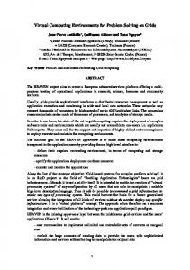
o Particle effects o Tile manipulation o Asset management o Behavior assignment • Scripting: Torquescript is a C++ like scripting language that ties all the various elements of a project together. It has the following features: o It has a library with hundreds of functions. It supports math, 3D math (vectors, matrices, and quaternions), object manipulation, and fileIO functions. o Object-oriented programming • GUI: Torque supports a customizable GUI. It supports widgets, containers, dialogs, transparency, skins support, support for Eastern languages • Sound: TGB uses the OpenAL sound library. The OpenAL is platform independent. It supports stereo, Streaming Sound, SFX/Music driver, 2D sound support for panning, volume, Doppler, cones,Multi-channel prioritized SFX manager, and Built-in Theora video codec playback. The main structure of our VRCCG is as follows: • Initialize graphics, input and sound • Load images of the components and instruments, and the sound files • Start virtual lab loop, the loop will be required to run around thirty times per second. In every loop the following will be executed: – Gather user input from the keyboard and mouse – Check whether there is a change in the connection that does need to run the mathematical simulation. – In case there is a change, convert the real graphical representation of the electric circuit into netlist format. – Get the outputs of the mathematical simulation. Depend on the instruments and the components in the lab we decided what to do. For example, for Digital Multimeter, the displayed value is updated. For led, we either turn the led on or off. For seven segment display, we turn off or display a digit on it…etc. – Test for ending criteria – if met, stop looping – Draw (render) screen, generate sounds and game controller feedback • Finalize graphics, input, and sound Using our VRCCG, we customized one for the basic electric lab as shown in Figure 1 and another one for logic electric lab as shown in Figure 2.
Space intentionally left blank
International Journal of Arts and Sciences 3(1): 9 - 17 (2009) CD-ROM. ISSN: 1944-6934 © InternationalJournal.org
Figure 1: Screen shot of the Virtual Basic Electric Lab
Figure 2: Screen Shot of the Virtual Logic Lab In the virtual basic lab, we implemented the following components and instruments: 1.Resistors (10 Ω, 22 Ω, 47 Ω, 100 Ω, 150 Ω, 220 Ω, 270 Ω, 330 Ω, 500 Ω, 600 Ω, 1KΩ, 1.5KΩ, 4.7KΩ, 5KΩ, 6.6KΩ, 10KΩ, 15kΩ, 20KΩ, 22KΩ, 33kΩ, 47KΩ, 100kΩ, 150KΩ, 1MΩ) 2.Wires (Red, Black, Blue, Green) 3.Diode 4.Switch
International Journal of Arts and Sciences 3(1): 9 - 17 (2009) CD-ROM. ISSN: 1944-6934 © InternationalJournal.org
5.Leds (Green, Red, Yellow) 6.Potentiometers (220Ω,1KΩ, 10KΩ, 500kΩ, 1MΩ) 7.Capacitors (10 nF, 0.22 µF, 4.7µF, 33µF, 47µF, 220µF, 470µF, 2200µF) 8.Breadboard 9.DC power supply 10. Digital Multimeter (measure voltage, current, and resistance) 11. Function Generator In the virtual logic lab, we implemented the following components and instruments: 1.Seven segment 2.BreadBoard 3.7400 IC (four independent gates each of which performs the logic NAND function) 4.7402 IC (four independent gates each of which performs the logic NOR function) 5.7404 IC (six independent gates each of which performs the logic INVERT function) 6.7408 IC (four independent gates each of which performs the logic AND function) 7.7410 IC (three independent gates each of which performs the logic NAND function) 8.7420 IC (two independent gates each of which performs the logic NAND function) 9.7432 IC (four independent gates each of which performs the logic OR function) 10. 7447 IC (BCD TO 7-SEGMENT DECODER ) 11. 7483 IC (full adders perform the addition of two 4-bit binary numbers) 12. 7486 IC (four independent gates each of which performs the logic exclusive-OR function) 13. 74139 IC (two separate two-line-to-four-line decoders) 14. 74151 IC (8-input multiplexer) 15. 74157 IC (Quad 2-input multiplexer) 16. 74181 IC (4-bit Arithmetic Logic Unit) 17. 7474 IC (two independent positive-edge-triggered D flip-flops with complementary outputs) 18. 7476 IC (two independent negative-edge-triggered J-K flip-flops with complementary outputs) 19. 74173 IC (four-bit register contains D-type flip-flops) 20. 74195 IC (4-bit register features parallel inputs, parallel outputs, J-K serial inputs, shift/load control input, and a direct overriding clear) 21. 74583 IC (four-bit register contains T-type flip-flops) 22. DC power supply 23. Digital Multimeter 24. Function Generator 25. Deep Switch 26. Wires (Red, Black, Blue, Green) 27. Leds (Green, Red, Yellow) 28. Resistors
4. A Case Study The purpose of our virtual labs is to allow students to verify the correctness of what they studies. As a basic assignment, students will be given a sheet of an experiment contains theoretical background, list of equipments and components, and execution steps. For example
International Journal of Arts and Sciences 3(1): 9 - 17 (2009) CD-ROM. ISSN: 1944-6934 © InternationalJournal.org
to verify the correctness of the Kirchhoff's voltage law (the law states that the algebraic sum of the voltages in any loop of a circuit is zero) the student has to apply the mathematical formulations learned during the course to calculate the correct values of the voltages using a circuit like the one shown in Figure 3. Then the student can build the circuit and verify the correctness of his calculations; Figure 4 shows a screen shot of our VRCCG after building the circuit in Figure 3. The net-list format generated by our VRCCG is shown as follows:
Figure 3: Schematic of the electric circuit
Figure 4: Screen shot from the virtual basic electric lab while doing the electric circuit in Figure 3.
1.R:R1 n65 n60 R="0 Ohm" 2.R:R2 n3 n33 R="1000 Ohm"
International Journal of Arts and Sciences 3(1): 9 - 17 (2009) CD-ROM. ISSN: 1944-6934 © InternationalJournal.org
3.R:R3 n8 n38 R="2200 Ohm" 4.R:R4 n13 n43 R="4700 Ohm" 5.R:R5 n64 n61 R="0 Ohm" 6.R:R6 n33 n38 R="0 Ohm" 7.R:R7 n8 n13 R="0 Ohm" 8.R:R8 n43 n78 R="0 Ohm" 9.R:R9 n76 n61 R="0 Ohm" 10. R:R10 n3 n60 R="0 Ohm" 11. R:R11 n72 n43 R="0 Ohm" 12. R:R12 n73 n13 R="0 Ohm" 13. R:R13 n66 n38 R="0 Ohm" 14. R:R14 n67 n8 R="0 Ohm" 15. R:R15 n80 n33 R="0 Ohm" 16. R:R16 n81 n3 R="0 Ohm" 17. Vdc:V1 n65 n64 U="12.00 V" 18. VProbe:M1 n66 n67 19. VProbe:M2 n72 n73 20. IProbe:M3 n76 n78 21. VProbe:M4 n80 n81 22. .DC:DC1 Solver="CroutLU"
Each line of the netlist format is explained here: 1. A wire connected between node n65 and n60 2. R2 is a resistor connected between node n3 and node n33 with a value of 1 kΩ. 3. R3 is a resistor connected between node n8 and node n38 with a value of 2.2 kΩ 4. R4 is a resistor connected between node n13 and node n43 with a value of 4.7 kΩ. 5. A wire connected between node n64 and node n61 6. A wire connected between node n33 and node n38 7. A wire connected between node n8 and node n13 8. A wire connected between node n43 and node n78 9. A wire connected between node n76 and node n61 10. A wire connected between node n3 and node n60 11. A wire connected between node n72 and node n61 12. A wire connected between node n73 and node n13 13. A wire connected between node n66 and node n38 14. A wire connected between node n67 and node n8 15. A wire connected between node n80 and node n33 16. A wire connected between node n81 and node n3 17. V1 represents a DC power supply between node n65 and n64with a DC voltage output of 12 volts. 18. M1 represents a Digital Multimeter adjusted to measure the voltage between node n66 and n67 19. M2 represents a Digital Multimeter adjusted to measure the voltage between node n72 and n73 20. M3 represents a Digital Multimeter adjusted to measure the current that goes from node n76 to n78
International Journal of Arts and Sciences 3(1): 9 - 17 (2009) CD-ROM. ISSN: 1944-6934 © InternationalJournal.org
21. M3 represents a Digital Multimeter adjusted to measure the voltage between node n80 and n81 22. This is the type of solver
5. Conclusions A power electronic virtual laboratory is developed and described. The developed virtual labs have shown to be a useful tool for teaching. They allow students to practically verify the results they obtained analytically. They enable students to evaluate and find the bugs in their project before submitting it to the instructors. The students will spend less time building their circuits. The students are guaranteed to build their circuits while in real labs there could be some missing parts. Each student in the course can build his own circuit, while in real labs may there are not enough equipments and/or components. The cost is much less than the real labs. The virtual labs allows for e-learning. The student can study from his home which is useful in many situations such as closing of schools due to swine flu. The system is a useful tool for distance learning where physical laboratory is not feasible. Finally, the whole package can be reached via the URL: http://www.asw-eng.svu.edu.eg/vldc/labs.htm
6. References [1] A. Francis and M. Couture, “Realism in the design process and credibility of a simulation-based virtual laboratory,” J. Comput. Assisted Learning, vol. 20, no. 1, pp. 40–49, Feb. 2004. [2] K. D. Forbus, S. E. Kuehne, P. B. Whalley, J. O. Everett, L. Ureel, M. Brokowski, and J. Baher, “CyclePad: An articulate virtual laboratory for engineering thermodynamics,” Artif. Intell., vol. 114, no. 1-2, pp. 297–347, Oct. 1999. [3] A. Bagnasco, P. Buschiazzo, D. Ponta, and M. Scapolla, “A learning resources centre for simulation and remote experimentation in electronics,” in Proc. PETRA, Athens, Greece, Jul. 2008, pp. 1–7. [4] T. R. Wyatt, P. Arduino, and E. J. Macari, “Assessment of a virtual laboratory for geotechnical engineering education,” Comput. Educ. J., vol. 10, no. 2, pp. 27–35, Apr. 2000. [5] A. R. White, P. E. McClean, and B. M. Slator, “The virtual cell: An interactive, virtual environment for cell biology,” in Proc. of World Conf. Educ. Multimedia, Hypermedia and Telecommun. (ED-MEDIA), Seattle, WA, Jun. 1999, pp. 1442–1443. [6] K. Wong, T. Wolf, S. Gorinsky, and J. Turner, “Teaching experiences with a virtual network laboratory,” in Proc. 38th SIGCSE Tech. Symp. Comput. Sci. Educ., Covington, KY, Mar. 2007, pp. 481–485. [7] Roy W. Goody, OrCAD PSpice for Windows (Volumes I-II), Prentice Hall, 2001.
Acknowledgment:
The authors would like to acknowledge the financial support of the European Commission-TEMPUS program. This work is a part of cooperative funded project with the grant holder institution; University of Innsbruck-Austria and the grant coordinator institution South valley University-Egypt.