instructions within the network. ... inside an EtherCAT network forming a daisy chain configuration. For the .... motor model from the same manufacturer, APM-FB04AMK, with ..... 880-896, 2015. [4] J. Ma ... Intelligent Service Robotics, vol. 9, no.
International Journal of Applied Engineering Research ISSN 0973-4562 Volume 11, Number 21 (2016) pp. 10586-10592 © Research India Publications. http://www.ripublication.com
Development and Control of an Omnidirectional Mobile Robot on an EtherCAT Network Raimarius Delgado Ph.D. Student, Department of Electrical and Information Engineering, Seoul National University of Science and Technology, Seoul, South Korea.
Wook Cheol Shin Student, Department of Electrical and Information Engineering, Seoul National University of Science and Technology, Seoul, South Korea.
Chang Hwi Hong Student, Department of Electrical and Information Engineering, Seoul National University of Science and Technology, Seoul, South Korea.
Byoung Wook Choi Professor, Department of Electrical and Information Engineering, Seoul National University of Science and Technology, Seoul, South Korea.
Abstract An omnidirectional mobile platform possesses the ability to be maneuvered in any direction instantaneously from any starting position. Control of such, requires mathematical operation that is crucial to occur within a specified time, particularly in autonomous navigation. In this paper, we present a development approach of a four-wheel omnidirectional mobile robot using mecanum wheels for directional flexibility and the recently standardized fieldbus, EtherCAT, for performing control instructions within the network. We implemented an open source EtherCAT master stack with a dual kernel real-time approach, Xenomai, configured to run alongside standard Linux on an embedded board to meet the real-time requirements of a main controller. The main controller schedules and executes multiple periodic tasks such as recognition of the target position, computation of the velocity commands to navigate along a target trajectory, and running the actual control task of servo drives. Feasibility of the EtherCAT solution for the mobile robot controller is determined thorough a statistical analysis in terms of periodicity of control task, corresponding jitter, and execution time. Actuation of the mobile robot is performed by implementing a proven trajectory planning algorithm considering the physical limits of the system to generate velocity commands that could track an S-curve path. Finally, accuracy of the mobile robot is determined by analyzing the encoder feedback and is represented in Cartesian space. Keywords: EtherCAT, Mecanum Wheels, Omnidirectional Mobile Robot, Xenomai, Real-time System.
INTRODUCTION Autonomous wheeled mobile robotics has been attracting a lot of interest from scientific, industrial, and governmental sectors. Yet, there are still underlying challenges to be addressed, especially in navigation control [1]. One of these important issues is the considerable amount of lateral and longitudinal slip present.
Corresponding Author
10586
This constraint is addressed by development of omnidirectional mobile robot platforms, which possess the ability to move spontaneously in any direction from any given position. Modeling of these platforms for the purpose of solving control problems has been addressed in different researches in [2-4]. This study presents the process of developing an omnidirectional mobile robot platform consisting of four mecanum or Ilon wheels [5]. In the development process of such platform, a key requirement to be considered for accurate manipulation is precise control period [6]. There are different reasons on which the control period is significant. First, the velocity commands given to each joint of the mobile robot should be kept in strict time sampling in order to smoothly track a given path. Second, data from the environment and other disturbances are acquired via different types of sensors which are updated periodically, if significant data loss occurs, the system would not be able to react accordingly and result to a failure. For example, a mobile robot would run directly to an obstacle instead of performing an avoidance scheme. Thus, real-time constraints should also be considered [7]. In order to achieve the real-time requirement of the mobile robot control system, we have selected one of standard realtime Ethernet protocols, EtherCAT. EtherCAT offers a wide range of features such as, flexible topology, costeffectiveness, and in-protocol synchronization scheme [8]. In this paper, each mecanum wheels are independently powered by an actuator consisting of a gear box, an AC motor, and an EtherCAT servo slave device. The four wheels are connected inside an EtherCAT network forming a daisy chain configuration. For the EtherCAT master, we have implemented an open source master distribution provided by IgH EtherCAT Master. The software is stacked on a dualkernel real-time system of Xenomai and standard Linux as implemented in our previous work [9]. As we have proven, implementation of the open-source EtherCAT master in a multicore ARM-based processor,
International Journal of Applied Engineering Research ISSN 0973-4562 Volume 11, Number 21 (2016) pp. 10586-10592 © Research India Publications. http://www.ripublication.com Freescale i.MX6Q SABRELite, shows stable results in fast operations, as much as 1 kHz cyclic commands. Thus, the EtherCAT control task in this study is configured to be executed within a period of 1 millisecond per cycle using the same development environment of the EtherCAT master stated on the previous research. After designing the mobile robot and developing the working environment of an EtherCAT master on an embedded platform, navigation of the four-wheel omnidirectional mobile robot using mecanum wheels is given consideration. Currently, there are different methods that work on conventional motion control of the omnidirectional movement as shown in the following researches [10-12]. Another contribution of this paper is giving a solution to the motion planning problem for the mobile robot by generating velocity profiles, for each of the joints, based on convolution that could track a curved path. An established study in [13] generates joint space velocity commands for two wheeled non-holonomic mobile robots while considering the heading angles of a planned path. We have reformulated the algorithm corresponding to the additional joints of our developed system. Moreover, the joint space velocities are also evaluated with respect to the inverse kinematics of the omnidirectional mobile robot. The performed experiments show promising results in the development process of an EtherCAT-based control platform that contemplates high accuracy and practicality in multi-functional applications such as mobile robots. The second section begins with a brief introduction regarding the advantages of EtherCAT as a fieldbus for mobile robot applications. The system architecture which describes both the hardware and software components of our developed system is discussed within in Section 3. Section 4 explains the path planning method that generates velocity commands for each joint of our four-wheel mobile robot. This section also discusses the reformulation that was performed for adapting a previous study into our system. The fifth section shows the experiment results by tracking a planned S-curve path. The last section closes the paper with the conclusion and some remarks regarding the developed EtherCAT-based omnidirectional mobile robot.
ETHERCAT IN MOBILE ROBOT CONTROL SYSTEM There are many highly specialized protocols that are used for industrial and automation control. Most of these protocols are designed for efficiency and reliability to support the operational performance requirements of the system to be developed. In other words, most of the industrial protocols disregard unnecessary features for the sake of accuracy and efficiency [15]. In a common mobile robot control network, serial communications that are already established such as RS-232, RS-485, and other industrial fieldbuses such as CAN protocol are adopted. Recently, Ethernet protocols are getting popular and the industry is slowly moving towards industrial Ethernet, however there are still advantages that Ethernet protocols cannot offer like the conventional fieldbus. These are reliability, handling message collision, low resource requirements, low cost implementation, real-time characteristics, and short error recovery time. Another crucial requirement for industrial fieldbuses is its non-destructive arbitration, meaning that the highest priority should still be transmitted even at high load without the expense of the transmission speed.
10587
Table 1. Performance Comparison of Fieldbus Protocols Features Specifications Communication Ethernet CAN RS-485 Speed 100 Mbps 1 Mbps 35 Mbps Data Packet 1486 Bytes 8 Bytes 1 Byte Node Distance 100 meters 40 meters 10 meters As shown in Table 1, the Ethernet protocol is theoretically the fastest in comparison to the conventional forms of communication. It can also transmit data from each node at an excellent maximum transmission speed of 100 Mbps while transmitting a data size of 1486 Bytes per cycle, in comparison to the 8 Bytes of CAN and 1 Byte of RS-485 in slower transmission rates. Also, the maximum distance between each node while conserving the data transmission rate is 100 meters per node unlike the other protocols that are only made for short distance communication. However, Ethernet protocols are still not considered to be entirely accepted as an industrial protocol because it is not deterministic; it does not support real-time controllability. The development of Real-time Ethernet Protocols (RTP) overcomes the real-time limitations as mentioned above. RTP networks are high speed communications using the original Ethernet specification which are designed for industrial applications that guarantee deterministic response time for very short transmission rate and hard real-time operation for periodic traffic of cyclic data delivery. In this research, we have selected EtherCAT for it offers the best real-time performance in terms of response time and communication jitter, it is widely supported with more than 3200 member companies in the EtherCAT Technology Group, and it also has an efficient clock synchronization for slaves down to hundreds of nanoseconds through special timing functionality, known as the Distributed Clock (DC) mechanism [16]. DEVELOPMENT OF AN OMNIDIRECTIONAL MOBILE ROBOT PLATFORM SUPPORTING ETHERCAT PROTOCOL A typical motion control system is used in industrial processes to actuate and carry task to move a specific load to a target position. In mobile robot application, the motion control system should provide a main controller that generates motion paths from an initial point to a target position and send commands, a drive that links the main controller and the actuators, and actuators that convert the commands into mechanical motion. The choice of actuator type is based on the specified power, speed, precision, or torque. These requirements are met as shown in the system structure to actuate a four-wheel mobile robot in Fig. 1. The developed system consists of a main controller that supports a distribution of an EtherCAT master, four digital servo drives containing EtherCAT slave controllers (ESC), and AC motors connected to absolute encoders, represented by the encircled “En”, within the figure. Encoders are essential to estimate the position of the mobile robot in feedback loop control. The components are connected by an Ethernet cable represented by dotted lines with bi-directional arrows.
International Journal of Applied Engineering Research ISSN 0973-4562 Volume 11, Number 21 (2016) pp. 10586-10592 © Research India Publications. http://www.ripublication.com
Figure 2. Design of an Omnidirectional Mobile Robot Using Mecanum Wheels
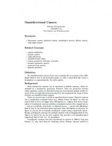
Figure 1. System Structure of a Four-wheel Mobile Robot A. Hardware components In our developed system, four EtherCAT servo drives are used that are manufactured by LS Mecapion, L7NA004B. The devices use CANopen-over-EtherCAT (CoE) for communication. For each slave, the process data objects are divided into 12 Bytes each for transmission and receipt, totaling to 24 Bytes of required data packets at each cycle. In addition, the servo drive supports processing of 19-bit serial encoder and provides three different control modes: velocity, position, and torque control. For the actuator, we attached a 400-Watt AC motor at each drive to serve as the left and right wheels of the mobile robot. To avoid incompatibility with the servo drive, we have chosen a motor model from the same manufacturer, APM-FB04AMK, with a rated maximum speed of 3000 revolutions per minute. Each motor is equipped with a built-in 19-bit absolute encoder that is used for accurate feedback loop control required to ensure that the load reaches the target command. Each of the motors is connected to a reducer gearbox with a reduction ratio of 1:100 for minimal error and higher mobility performance in high speed actuation. In order to achieve omnidirectionality, mecanum wheels are connected that consist of 12 rollers with a diameter of 203 mm. Each roller diameter is 67 mm. Common mecanum wheel mobile robots are either in the form of a parallelogram. The mecanum wheels are attached to the robot system to constitute a basic 45° driving system. The omnidirectional capabilities of the platform are highly dependent on the contact of each wheel on the surface. Hence, most of the proprietary and commercial designs of a mecanum wheel driving system include a suspension. In our design, the wheels and motor assembly are mounted directly on the chassis made from aluminum frame with the dimensions of approximately 700 mm and 450 mm in length and width, respectively. Fig. 2 shows the developed design without the top plate, for making the interior as visible as possible.
10588
B. Software components From our previous study in [9], the latest version of embedded Linux that can be implemented on the ARM-based embedded platform, i.MX6Q SABRELite is kernel 3.14.15 provided in ARMv7 Multiplatform repository. The kernel is patched with ADEOS, which enables multiple domains to exist in the same hardware through an abstraction layer. This enables the embedded hardware to run the standard Linux kernel alongside Xenomai. Xenomai is the popular dual-kernel approach distribution of real-time Linux. It provides hard real-time support to user space applications with synchronization and scheduling mechanisms such as mutex, semaphores, event flags, message queues, and so forth. We implemented the latest Xenomai version that is suitable for the latest kernel, Xenomai 2.6.4. In order to communicate with the EtherCAT slaves, we installed an open source distribution of an EtherCAT Master provided by IgH. The latest version available is IgH EtherCAT 1.5.2. To make sure that there will be no problems to be encountered during installation of both Xenomai and IgH EtherCAT master libraries, the toolchain to be used is gcc-linaro-arm-linux-gnueabihf-4.8.3. The detailed software architecture of the EtherCAT master is shown in Fig. 3.
Figure 3. Software Architecture of an Embedded EtherCAT Master based on Dual-kernel Approach of Xenomai
International Journal of Applied Engineering Research ISSN 0973-4562 Volume 11, Number 21 (2016) pp. 10586-10592 © Research India Publications. http://www.ripublication.com For the purpose of assessing the real-time performance of the EtherCAT master using the open-source library, a basic experiment of a simple cyclic control task is realized reading a value from a buffer and sending it as velocity command to each of the EtherCAT slaves. The control application was developed with a period of 1 ms in user space of Xenomai; using the native application programming interface for both task management and timing services. Also, the EtherCAT master was configured to use the generic driver provided by IgH EtherCAT master. The performance metrics used are the actual cycle time as probed by the Xenomai timer, the difference of the actual cycle time and expected cycle called the jitter, and task execution time. Execution time is the time interval on where the real-time task receives the data from the hardware buffer, processes the data, and sending it back to the hardware for sending to the EtherCAT slaves. The detailed instruction for this performance evaluation method is explained in [9]. Fig. 4 plots the distribution of 60,000 samples acquired by running the experiment control task for 1 minute. As expected, the system is stable as evident in the histogram with most of the samples are in the average time of 1 ms. Further results include 1.009293 ms and 0.9928884 ms for maximum and minimum values, respectively. The acquired data tend to be closer to the mean with a low standard deviation of 0.000684 ms. These values are consistent with the jitter showing 0.523 μs, 9.923 μs, and 0.442 μs respectively for average, maximum and standard deviation. In the configuration stated above, the EtherCAT execution time, not shown in the figure, is calculated to have an average value of 97.117 μs with a standard deviation of 2.540 μs. The worst case value for the one-minute experiment is measured to be 236.848 μs, on which the highest delay occurs when the real-time task is accessing the buffer of the Ethernet hardware through direct memory access. Since the i.MX6Q SABRELite uses Fast Ethernet Controller based on Motorola MPC8xx, IgH EtherCAT master can only support the generic driver. Although not reported here, the worst case value when using a supported native driver, Realtek R8169 for example, is 82.581 μs. These results show that the current implementation of the EtherCAT master is suitable for hard real-time requirements of a mobile robot controller.
Figure 4. Distribution Plot of the Experimental EtherCAT Control Task (1 ms period)
10589
PATH PLANNING For the mobile robot to travel within a known environment, a parameterized planned path is an essential requirement. To follow the planned path, the position at a uniform sampling point is represented as a function of time. Thus, the instantaneous velocity at each sampling point is calculated to generate a velocity profile. Path planning is a fundamental problem to be solved in order to operate a mobile robot autonomously. Herein, we reformulate an established algorithm presented in [13] to accommodate the joint space velocities of a four-wheel omnidirectional mobile robot by solving the corresponding forward and inverse kinematics of such system [10]. According to the previous research, first, a planned path is designed in the Cartesian space using a parameterized Scurve from a starting point (0 m, 0 m) to a desired terminal point (3 m, 1.5 m) as shown in Fig. 5. Fig. 6 shows the generated linear and angular velocity from a starting and terminal velocity of 0 m/s and 0 rad/s. The mobile robot could track the travel distance of 3.39 m within 10.28 s of total travel. The velocity profile is generated considering the physical limits of 0.5 m/s, 0.2 m/s2, and 0.2 m/s3 for the maximum velocity, acceleration, and jerk, respectively.
Figure 5. S-Curve Planned Path
Figure 6. Linear and Angular Velocity Profile to Track the S-Curve
International Journal of Applied Engineering Research ISSN 0973-4562 Volume 11, Number 21 (2016) pp. 10586-10592 © Research India Publications. http://www.ripublication.com Assuming that the S-Curve path is defined by a sampling time bounded parameter denoted as u(t), on where 0 ≤ u(t) ≤ 1, then each point along the curve is defined as a function of the parameter or expressed as the coordinate, (x(u(t)), y(u(t))). In definition, vx and vy are the rate of change of position in each respective axis. Thus, it can be calculated as the first-order derivative of each component of the S-Curve, or:
dx(u (t ) vx (t ) dt v (t ) dy (u (t ) y dt
(3)
Hereon, the heading angle from the center of the mobile robot, θc, at each point along the curve is calculated as:
c (u (t )) tan 1
Figure 7. Kinematics Model of an Omnidirectional Mobile Robot Using Mecanum Wheels The actual velocity commands to actuate the mobile robot is the angular velocity at each of its wheels as represented by ωi (i=0,1,2,3) in the kinematics model shown in Fig. 7. Each of the wheels is driven individually for the mobile robot to perform either lateral or radial movement. The mathematical model of the movement is expressed in the inverse kinematics:
v0 0 1 1 ( L l ) v vx 1 R 1 1 1 ( L l ) v v2 2 1 1 ( L l ) y z v3 3 1 1 ( L l )
(1)
dy (u (t )) dx(u (t ))
(4)
Therefore, the angular velocity with respect to the center of the mobile robot is expressed as:
z (t )
dc (u (t )) dt
(5)
Fig. 8 below shows the lateral velocities generated from the S-Curve using (3). The heading angles at each sampling point calculated using and (4) is also shown at the bottommost of the figure. For a smooth S-Curve, the rate of change in the xaxis is higher than that of the y-axis as clearly shown in the figure below. Also, the central angular velocity calculated using (5) is equal to the bottom part of Fig. 6.
where, vi (i=0,1,2,3) is the linear velocity for demonstrated by each of the wheels, R is the radius of the wheel, L and l denote the distances from the center of the robot frame to the center of the wheels with respect to the vx and vy axes, respectively. vx denotes the longitudinal velocity while vy denotes the transversal velocity of the mobile robot. ωz denotes the angular velocity or the rate on which the mobile robot is turning around its central axis. From (1), it can be concluded that there is a relationship between the central velocity of the mobile robot and angular velocity at each of the wheels. The joint space velocities are derived and calculated using the following equation:
0 1 2 3
1 (vx v y ( L l ) z ) R 1 (vx v y ( L l ) z ) R 1 (vx v y ( L l ) z ) R 1 (vx v y ( L l ) z ) R
(2) Figure 8. Lateral (Longitudinal and Transversal) Velocities and Heading Angles on the Center of the Mobile Robot
10590
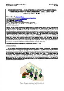
International Journal of Applied Engineering Research ISSN 0973-4562 Volume 11, Number 21 (2016) pp. 10586-10592 © Research India Publications. http://www.ripublication.com EXPERIMENT RESULTS Using the presented trajectory generation techniques in Section II, driving experiment was performed on an ideal environment where the wheels of the mobile robot are lifted to impose freewheeling motion to avoid disturbances that conveys uncertainties such as slip and friction. The velocity profile is generated in the user space of Xenomai and these commands are sent to the mobile robot using CoE protocol on a bounded period of 1 ms. In this example, we generated a path from an initial point (0, 0, 0°) to the desired terminal point (3, 1.5, 0°), with both initial and terminal velocities at 0 m/s. The physical limits of the mobile robot required to generate velocity commands are based on the actual constraints of the actuators. According to the motor specifications, the limits are stated as 0.3 m/s for the maximum velocity limit, 0.2 m/s2 for the maximum tangential acceleration, and 0.2 m/s3 for the maximum jerk. The central velocity is produced using the convolution operator in [13] and the actual joint-space velocity commands for the omnidirectional mobile robot require velocity profiles for each wheel are calculated using (2). The diameter of the wheels is 203 mm, and the distance from the center frame to the center of the wheels in both longitudinal and transversal direction is 287 and 305 mm, respectively. Fig. 9 shows the velocity profile for each wheels of the mobile robot platform that could track the path of 3.386 m in 13.79 s. In this figure, the solid lines labeled as vi ref (i=0,1,2,3) denote the generated angular velocities the set of mecanum wheels. The corresponding encoder values from the mobile robot is acquired and compared with the calculated velocity represented by the different markers labeled as vi real (i=0,1,2,3). Also, the central velocity generated using convolution is represented by the black solid line labeled as vc. As shown in the figure, the actual values from the encoder shows oscillating results which is expected for we are using an absolute encoder. Although not reported in this paper, the current system shows lesser noise than previous experiment results without a gearbox. Herein, a reducer gearbox with a high reduction ratio of 1:100 is used. In case of lower reduction ratio, the noise is due to the maximum speed that the encoder can run electrically is required to be considered.
Figure 9. Joint Space Velocity Profiles to Track an S-Curve
10591
After acquisition of the data from the encoder through EtherCAT, the actual velocity values are analyzed using the robot forward kinematics to generate a trajectory in the Cartesian coordinate plane. The actual lateral velocities are calculated using the following equations:
R vx (t ) (0 1 2 3 ) 4 v (t ) ( ) R 0 1 2 3 y 4
(6)
The trajectory is generated by integrating the differences between all segments in both the x and y axes to the initial position values of, xi and yi, in this case from the starting point at (0 m, 0 m):
x (t ) x t v (t )dt i 0 x c t yc (t ) yi v y (t )dt 0
(7)
Analysis of the encoder data shows that the mobile robot was able to track the planned path accurately with an error margin of 36 mm on the x axis and less than 1 mm on the y axis at the terminal point reaching the coordinate, (2.964 m, 1.499). While moving along the path, the calculated travel time of the mobile robot is 13.79 s and the integrated actual length of the planned path is calculated as 3.386 m. Although the terminal points show minimal error, there are points along the curve where the least square error is visible as shown in the comparison plot in Cartesian space in Fig. 10. One of the obvious causes of these error values is that the joint space velocities is greater than the configured maximum velocity of the system, which could result to drift and tracking issues from the original planned path. These problems are beyond the scope of this paper since these would not occur when the mobile robot is exhibiting freewheeling motion.
Figure 10. Trajectory tracking in Cartesian space
International Journal of Applied Engineering Research ISSN 0973-4562 Volume 11, Number 21 (2016) pp. 10586-10592 © Research India Publications. http://www.ripublication.com Thus, an accurate trajectory that could track the planned path was possible to be generated although the maximum velocity limit was not met. Moreover, we note that feedback control is also not adopted within this experiment since the focus of the test is to guarantee the real-time characteristics in using the EtherCAT protocol from open source software rather than performance of the control algorithm.
[4]
[5] CONCLUSION In this paper, an omnidirectional mobile robot using Mecanum wheels is developed supporting the recently standardized fieldbus protocol, EtherCAT. An open source EtherCAT Master provided by IgH EtherCAT Master was implemented on an ARM-based embedded board, Freescale i.MX6Q SABRELite that serves as the main controller of the whole system. Each of the mecanum wheels are powered with servo drives that serves as the EtherCAT slaves using CoE protocol for communication. Timing analysis has been carried out aimed at evaluating the real-time performance through the periodicity of the cyclic control task on the EtherCAT master while connected to the four slaves using actual cycle time, jitter, and execution time as test criterions. For actual actuation, a proven path planning technique originally designed for two-wheeled differential drive mobile robot was reformulated to accommodate the addition joints of the fourwheel omnidirectional mobile robot. The reformulation is achieved by solving the forward and inverse kinematics of such system. Finally, performance analysis for control applications has been performed by generating velocity commands that could produce a trajectory to track a curved planned path. The results of the experiment show that that an open source EtherCAT Master is feasible to serve as the main controller of a mobile robot control system with minimal jitter and acceptable execution time. Although the results show minimal error at the terminal point during actuation, there is a need for further research regarding consideration of joint space velocities to minimize the position error that occur while the mobile robot is navigating along a curved path. Also, detailed analysis regarding the validity of the system in more complicated control application such feedback loop control is taken into consideration as future work.
[6]
[7]
[8] [9]
[10]
[11]
[12]
[13] ACKNOWLEDGMENT This study was financially supported by Seoul National University of Science and Technology.
[14]
REFERENCES [1]
[2]
[3]
E. Rodriguez-Seda, C. Tang, M.W. Spong, and D.M. Stipanovic, “Trajectory tracking with collision avoidance for nonholonomic vehicles with acceleration constraints and limited sensing,” International Journal of Robotics Research, vol. 33, no. 12, pp. 1569-1592, 2012. J.E.M. Salih, M. Rizon, and S. Yaacob, “Designing omnidirectional mobile robot with mecanum wheel,” American Journal of Applied Sciences, vol. 12, no. 5, pp. 1831-1835, 2006. G. Ishigami, K. Iagnemma, J. Overholt, and G. Hudas
10592
[15] [16]
“Design, development, and mobility evaluation of an omnidirectional mobile robot for rough terrain,” Journal of Field Robotics, vol. 32, no. 6, pp. 880-896, 2015. J. Ma, H. Kharboutly, A. Benali, F.B. Amar, and M. Bouzit, “Design of omnidirectional mobile platform for balance analysis,” IEEE/ASME Transactions on Mechatronics, vol. 19, no. 6, pp. 1872-1880, 2014. B.E. Ilon, “Wheels for a course stable selfpropelling vehicle movable in any desired direction on the ground or some other base,” U.S. Patent 3 876 255, Apr 8, 1975. Y. Moon, N.Y. Ko, K. Lee, Y. Bae, and J.K. Park, “Real-time EtherCAT master implementation on Xenomai for a Robot System,” International Journal of Fuzzy Logic and Intelligent Systems, vol. 9, no. 3, pp. 244-248, 2009. R. Delgado and B.W. Choi, “Time optimal path planning while considering physical and geometrical limits during obstacle avoidance,” International Journal of Applied Engineering Research, vol. 10, no. 19, pp. 40672-40678, 2015. EtherCAT Technology Group, http:// www.ethercat.org/. R. Delgado, C.H. Hong, W.C. Shin, and B.W. Choi, “Implementation and performance analysis of an EtherCAT Master on the latest real-time embedded Linux,” International Journal of Applied Engineering Research, vol. 10, no. 24, pp. 44603-44609, 2015. H. Taheri, B. Qiao, and N. Ghaeminezhad, “Kinematic model of a four mecanum wheeled mobile robot,” International Journal of Computer Applications, vol. 113, no. 3, pp. 6-9, 2015. E.-J. Jung, B.-J. Yi, and W. Kim, “Kinematic analysis and motion planning for a planar multiarticulated omnidirectional mobile robot,” IEEE/ASME Transactions on Mechatronics, vol. 20, no. 6, pp. 29832995, 2015. Y.K. Park, P. Lee, J.K. Choi, and K.S. Byun, “Analysis of factors related to vertical vibration of continuous alternate wheels for omnidirectional mobile robots,” Intelligent Service Robotics, vol. 9, no. 3, pp. 207-216, 2016. R. Delgado and B.W. Choi, “Practical high curvature path planning algorithm in joint space,” IET Electronics Letters, vol. 51, no. 6, pp. 469-471, 2015. G.J. Yang, R. Delgado, and B.W. Choi, “A practical joint-space trajectory generation method based on convolution in real-time control,” International Journal of Advanced Robotic Systems, vol. 13, no. 56, pp. 1-12, 2016. E.D. Knapp and J.T. Langill, Industrial Network Security. Waltham, MA: Syngress, 2015. G. Cena, I.C. Bertolotti, S. Scanxio, A. Valenzano, and C. Zunino, “Evaluation of EtherCAT distributed clock performance,” IEEE Transactions on Industrial Informatics, vol. 8, no. 1, pp. 20-29, 2012.