ABCM Symposium Series in Mechatronics - Vol. 5 Copyright © 2012 by ABCM
Section VI – Metrology Page 898
DEVELOPMENT OF AN ADAPTIVE ROBOT CONTROL CLIENT FOR THE INTEGRATION OF THE iGPS SYSTEM AND A 12DOF NONCONVENTIONAL ROBOT Glauber Mosqueira,
[email protected] Anderson Harayashiki Moreira,
[email protected] Luís Fernando Ferreira Furtado,
[email protected]
Luís G. Trabasso,
[email protected] ITA – Instituto Tecnológico de Aeronáutica LAME – Laboratório de Automação da Montagem Estrural de Aeronaves Praça Marechal Eduardo Gomes, 50 - Vila das Acácias - São José dos Campos 12.228-900 - São Paulo, Brazil
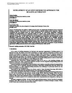
Abstract. The ever-growing need to improve manufacturing processes has recently led to an increase in the number of automation solutions employed to assemble aircraft structural elements. One of the key aspects of this process is the leveling and alignment of each fuselage section with respect to the other, to allow them to be joined together. Several conventional and non-conventional robotic solutions have been proposed to position the 6DOF of a fuselage barrel. A common denominator among many of them is the feedback control of the robot position through a metrology system, a compensation/correction mechanism named Adaptive Robot Control (ARC). This work describes the development of an ARC communication client for the integration between an indoor GPS (iGPS) metrology system and a 12DOF nonconventional robot. The robot is comprised of 4 towers with 3 cartesian DOF each; interpolated, they yield a 6DOF motion for a fuselage barrel. The iGPS system comes off-the-shelf with an ARC server that dictates most of the communication, done via User Datagram Protocol (UDP) and Transmission Control Protocol (TCP). The other side of the communication is done with the robot controller. This article describes the specifics of the communication and also how the client uses the metrology data to recalculate and update the position of the robot. Keywords: Robot-metrology communication, Adaptive robot control, TCP, UDP 1. INTRODUCTION The ever-growing need to improve manufacturing processes has led to an increase, in recent years, in the number of automation solutions employed to assemble aircraft structural elements (Sahr et al., 2009). The work described herein is part of the activities being carried at the Aircraft Structure Assembly Automation Laboratory (ASAA Lab). An outcome of a partnership between the Instituto Tecnológico de Aeronáutica (ITA) and the Brazilian aerospace sector, the ASAA lab is developing an automated assembly process for aircraft fuselages. This work is a first step towards the modernization of the aerospace manufacturing techniques in Brazil, aiming at the better product quality and faster production times brought by automation. Given the current development pace of this area for the aerospace industry in general, initiatives like the ASAA Lab are crucial to keep the Brazilian companies competitive. They represent an investment not only in the short term fabrication capacities, but also in a long term know-how accumulation and human resources training in automation processes.
Figure 1. Computer simulation of the ASAA robotic cell
ABCM Symposium Series in Mechatronics - Vol. 5 Copyright © 2012 by ABCM
Section VI – Metrology Page 899
The robotic cell at the ASAA lab is comprised of several modules (as partially shown in Fig.1), including NikonTM’s indoor GPS (iGPS) metrology system and NIVA (NIVelamento e Alinhamento, Portuguese for Leveling and Alignment), a 12DOF non-conventional robot. The NIVA robot will be used to position and orient a fuselage barrel in space, leveling and aligning it with respect to a fixed barrel. In order to increase the robot’s positioning accuracy, the iGPS system will be used as a feedback source in a control loop, through a mechanism known as Adaptive Robot Control (ARC). The off-the-shelf iGPS system is able to communicate directly with commercially available robots, such as KUKATM manipulators. However, because the NIVA is a custom-made robot, an integration solution had to be developed. This paper presents the development of this solution and is organized as follows: section 2 describes the iGPS system, the NIVA robot and the ARC mechanism; section 3 presents the problem constrains, the requirements of the communication protocol and a theoretical background; finally, section 4 details the solution implemented and section 5 presents the conclusion. 2. EQUIPMENT DESCRIPTION 2.1. The iGPS metrology system Muelaner et al. (2009) define the iGPS as “a large volume frameless and distributed coordinate measurement machine”. The system is comprised of sensors and a transmitter network. A sensor consists of two collinear sensing elements, and its position is defined in spherical coordinates (elevation, azimuth and range). Each transmitter emits a LED pulse and also has a rotating head that sweeps the measurement volume with fanned lasers at 40Hz. Since the lasers are fanned, the upper sensing element will receive the two signals at a different rate if compared to the lower element, as shown in Figure 2 (left). This difference can be used to calculate the elevation of a sensor relative to a transmitter. Because of this, sensors must be used in a vertical alignment. The azimuth is calculated through the time difference between the LED pulse and the midpoint between the two laser fans, as shown in Figure 2 (middle).
Figure 2. Calculation of the elevation (left) and azimuth (middle) of an iGPS sensor with spherical coordinates (right) (Nikon Metrology, 2010a) Considering Figure 2 (right), one may notice that with a single transmitter the range coordinate of a sensor is undetermined. A second transmitter is necessary for this calculation. Added transmitters increase the accuracy of the range measurement by redundancy (Figure 3, left). Finally, bundling calculations position the transmitters relative to each other through ray intersection. A calibration bar with known length is used to set a network scale (Figure 3, right).
Figure 3. Calculation of the range coordinate for a sensor (left) and of the network scale (right)
ABCM Symposium Series in Mechatronics - Vol. 5 Copyright © 2012 by ABCM
Section VI – Metrology Page 900
(Nikon Metrology, 2010a) The description above lays the principles to determine the position of a sensor with respect to the network. With multiple sensors placed on a tool or reference, it is possible to create a coordinate system (frame) for it. Because the iGPS system has tracking capabilities, it is possible to calculate the position of this frame as it moves in space. 2.2. The NIVA robot The NIVA robot is comprised of four towers and each has 3DOF (degrees of freedom) in the Cartesian axes ( Figure 4, left). Interpolated, the towers yield 6DOF ( Figure 4, right). The robot is controlled by a CNC (Computer Numeric Control). The 6DOF mean that a fuselage barrel atop the robot can be translated in X, Y, Z or rotated in roll, pitch and yall. These movements are used to level and align the fuselage barrel with respect to a second, fixed barrel. The purpose of this section is to illustrate the ways in which the robot can actuate; the details of its controller won’t be expanded here.
Figure 4. Schematic of the NIVA robot and its DOF in independent mode (left) and in interpolated mode (right) 2.3. The ARC correction mechanism In the context of aircraft assembly, the usual configuration for a system composed of an actuator and a metrology device is shown in Figure 5. Sensors are placed in the fixture that holds the target part and also in the robot tool. This way, the relationship between the part and the tool is always known, even if the fixture and/or the tool are moved. The only requirement is that the sensors must stay rigidly attached to the fixture/tool. Whenever the robot moves to a desired point, the ARC correction routine can be evoked. Once the robot stops moving, the metrology system checks the actual position and compares it with the nominal data. It then calculates the deviation and, if it is out of the predefined tolerance, it tells the robot to correct by that amount. The controller stays in this loop until the specified tolerance is achieved or until a timeout occurs. Because the metrology reading is more accurate than the robot positioning, the correction results in a better positioning.
Figure 5. Correction of a robot tool frame according to the nominal frame, referenced to a global frame (Nikon Metrology, 2010b) The literature contains many works that discuss the limitations of current industrial robots and the need for a feedback source to improve their positional accuracy and satisfy the tight tolerances of the aircraft industry (DeVlieg et
ABCM Symposium Series in Mechatronics - Vol. 5 Copyright © 2012 by ABCM
Section VI – Metrology Page 901
al., 2002, Summers, 2005 and Kihlman and Loser, 2003). The concept behind ARC fits this solutions domain and justifies the effort described in this article. 3. PROBLEM CONSTRAINS AND THEORY BACKGROUND 3.1. Communication protocol In order to integrate the iGPS system to the NIVA robot and thus enable the ARC mechanism, a client had to be developed to act as a middleware and to intermediate the communication between the two systems (Figure 6). The dashed box denotes that the client is encapsulated in the same computer that controls the NIVA robot. The function of the client is to parse the information received by the iGPS system in a way that the robot can understand, since these equipments do not share a common interface. On the same token, it will format the NIVA replies in order to send it back to the iGPS system. Therefore, the client features a two-way (i.e. read/write) communication with both sides it connects to.
NIVA robot
Custom client
iGPS ARC Server
Figure 6. Diagram showing the client as a middleware between the robot and the iGPS server On the iGPS side, the client must comply with a communication protocol dictated by the iGPS suite. Figure 7 contains a diagram with the schematic of the iGPS ARC communication protocol. When the client is turned on, it starts to listen to UDP (User Datagram Protocol) connections on a predefined port, and waits until a proper packet is received. The iGPS computer then broadcasts a predefined message looking for possible listeners. Upon receiving the broadcast packet, the client replies accordingly. With the UDP reply, the iGPS computer can determine the IP (Internet Protocol) address and port from which it was sent. Then, it sends commands to initialize the TCP connection and soon it is established. UDP is only used to locate the computers on the network. Switching to TCP is necessary because UDP is not a reliable protocol, i.e., it does not acknowledge the receipt of packets (Tanenbaum, 2009).
Figure 7. Schematic of the iGPS ARC communication protocol On the robot side, the client software runs on the same suite as the NIVA software, although the codes run on separate instances. Thus, the communication is done intra LabVIEWTM by sharing variables between the codes. 3.2. Sockets and .NET Sockets are endpoints for communication between two machines (Oracle, 2011). The .NET socket library, which is available in computer languages such as Java and C#, greatly simplifies the access to ports by dealing with the lowlevel control of the network traffic. It also allows the creation of client/server pairs. If a listener program such as the client represented in Figure 8 wants to use a port through TCP, it must first create an object called a server socket. If the port is free, the program binds to the port through the socket and takes exclusive use of it while necessary. No more than one program can bind to a port at the same time. For the actual input/output (I/O) of data, the program must create a second socket called a listener socket. This object enables the code to start to accept connections once the port is bind. A multi-threaded code is able to accept multiple incoming connections simultaneously, but this discussion is beyond the scope of this paper. Also, the observant reader will notice that in general listener codes are called servers; in this case, however, because the iGPS software was already named a server, it was decided to name this listener a client.
ABCM Symposium Series in Mechatronics - Vol. 5 Copyright © 2012 by ABCM
Section VI – Metrology Page 902
Once the listener socket receives a valid request, it establishes a connection. The socket has dedicated I/O buffer objects through which data is exchanged. Up to here, when creating the sockets, the code follows a fairly standard format. The proper logic that differentiates each program is built around the I/O buffers. In this client, the input buffer receives only text string containing a command from the iGPS computer. The command is then filtered in a case structure and the appropriate text string reply is sent through the output buffer. This lays the basic read/write functionality of the client. Input buffer Subnet
Port
Server socket
Listener socket
Client Output buffer Program logic
Figure 8. TCP Socket structure in .NET 4. IMPLEMENTATION 4.1. Design philosophy - overview The client was conceived to be a background program, with no operator input needed. Because the code is actually an interface between two machines, the client man-machine interface (Figure 9) features only a STOP button and an event-driven log. The RUN button is standard in the panel of LabVIEWTM applications. The log presents the most relevant events, such as a command request, and their occurrence time. It was useful during the development phase and it might also be useful in identifying the cause for eventual failures.
Figure 9. User interface for the client software
ABCM Symposium Series in Mechatronics - Vol. 5 Copyright © 2012 by ABCM
Section VI – Metrology Page 903
4.2. Implementation in parallel loops LabVIEWTM offers an ease of calculation through the ability to process loops in parallel. In this client, the main routine has five processing loops, as presented in Figure 10. The read and write loops contain the logic necessary to deal with the I/O data of the buffers, as discussed in the previous section. The watch loop contains a special subroutine that watches a list of variables according to a demand by the iGPS computer. If a variable is being watched, whenever its value changes a text string is sent to the iGPS computer informing the new value. Variables can be of the type Boolean, integer, string or double precision. The log loop keeps the human-machine interface updated as soon as an event is registered by the controller.
Read loop Log loop
Write loop
Watch loop
ARC_POS_CHK loop Main routine
Figure 10. Implementation of the main client routine in parallel loops Finally, the ARC_POS_CHK is a flag-triggered subroutine that establishes the connection between the client and the NIVA robot. This subroutine is where the ARC mechanism properly said is located. In the robot controller, a predefined command raises a flag whenever the positioning process is over and a correction is desired. With the flag, the ARC_POS_CHK routine is triggered. Then, the robot reading, the measurement reading and the nominal position are compared to calculate the correction, according to what was described in section 2.3. 4.3. Analysis – Network packet captures In order to debug the connection, the Wireshark® free, open-source network sniffer was used to analyze the packet traffic. It provides an in-depth view of what is being transmitted and received at the bit level. Because information can be separated by filtering out protocol streams, it is useful to sort out errors that can’t be made explicit in the code. With the sniffer, it was also possible to verify that the packets were indeed being sent and received as expected. Furthermore, time information was useful to evaluate and validate the speed/performance of the code, especially regarding an appropriate information processing by the parallel loops.
Figure 11. Example of a network capture during client usage 5. CONCLUSION The improvement of the positioning accuracy of robots, a relevant problem to the aircraft industry, was discussed in this paper. Whenever a large robotic cell is developed, it is likely that the cell devices will be supplied by different manufacturers and thus integration plays a major role in projects of this type. This article presented a technical discussion about the problem of integrating a metrology system, Nikon’s iGPS, to a custom-made robot for the leveling and alignment of fuselage barrels. The background information of both systems was presented. A working solution, the communication client, was presented and its development was analyzed. The theoretical foundation behind the client was exposed, including the communication protocol that supports it. The UDP and TCP
ABCM Symposium Series in Mechatronics - Vol. 5 Copyright © 2012 by ABCM
Section VI – Metrology Page 904
protocols were employed in the solution, the latter through the use of the .NET class of sockets. The solution interface has been shown and it was highlighted that it was conceived to be simple and run in the background with minimal operator interference. The client has been analyzed with a network sniffer to assess its performance and to ensure the adequacy of its operation. With the analysis results, is possible to conclude that the solution developed has achieved its purpose, being useful and reliable. Future work will assess the improvement of the position accuracy in the alignment process with the closed loop configuration over the previous open loop one. 6. ACKNOWLEDGEMENTS The authors would like to thank Financiadora de Estudos e Projetos (FINEP) and Conselho Nacional de Desenvolvimento Científico e Tecnológico (CNPq) for their financial support, Nikon Metrology and National Instruments for product support and Empresa Brasileira de Aeronáutica S/A (Embraer) for the support received for this project on visits to their premises. 7. REFERENCES DeVlieg, R., Sitton, K., Feikert, E., Inman, J., 2002. “ONCE (ONe-sided Cell End effector) Robotic Drilling System”, Automated Fastening Conference and Exhibition 2002. SAE Ref: 2002-01-2626. Kihlman, H., Loser, R., 2003. “6DOF Metrology-integrated Robot Control”, Proceedings of the Automated Fastening Conference and Exposition 2003. SAE Ref: 2003-01-2961. Muelaner, J., Wang, Z., Jamshidi, J., Maropoulos, P., 2009. “Verification of the indoor GPS system by comparison with points calibrated using a network of laser tracker measurements”, 6th International Conference on Digital Enterprise Technology. Nikon Metrology, 2010a. “An iGPS Overview – flash presentation”, Private Communication. Nikon Metrology, 2010b. “Adaptive Robot Control – flash presentation”, Private Communication. Oracle, 2011. “java.net class socket”, Oracle Corporation, 31 Mar. 2011 . Sarh, B., Buttrick, J., Munk, C., Bossi, R., 2009. “Aircraft Manufacturing and Assembly”. Springer Handbook of Automation, pp. 893-910. Springer, Heidelberg. Summers, M., 2005. “Robot Capability Test and Development of Industrial Robot Positioning System for the Aerospace Industry”, SAE Transactions. SAE Ref: 2005-01-3336 Tanenbaum, A. S., 2009. “Computer Networks”. 4th ed., Ed. Pretience Hall, pp. 524-555. 8. RESPONSIBILITY NOTICE The authors are the only responsible for the printed material included in this paper.