Development and Design Validation of Pneumatic Tool for Stem Seal & Collet Fitment of SL-90 ... 2,3,4 (Under Graduate students: Mechanical Engineering Department, MMCOE Pune). ... of assembly is carried out using CATIA V5 software which gives a correct perception of the .... [5] âCompany Profileâ, www.kirloskar.com/.
Development and Design Validation of Pneumatic Tool for Stem Seal & Collet Fitment of SL-90 Engine Cylinder Head.
53
Development and Design Validation of Pneumatic Tool for Stem Seal & Collet Fitment of SL-90 Engine Cylinder Head. Deulgaonkar Vikas Radhakrishna1, Shivang Bhatnagar2, Ashish Karve3 and Varun Kelkar4 1
Senior Lecturer, Mechanical Engineering, MMCOE, Pune. (Under Graduate students: Mechanical Engineering Department, MMCOE Pune).
2,3,4
Abstract: The present work deals with the design development and design validation of special purpose pneumatic tool to optimize the steps in assembly and consequently production process. An attempt is made to develop a pneumatic tool that uses power of compressed air to generate a force enough to press the stem seal and the collet, collet cup collectively. Detailed calculations of section properties of various members of the tool assembly are carried out. Calculation for force to be generated is done by considering possibilities i.e. hydraulic generation and pneumatic. Prior to fabrication, detailed CAD modeling of each component of assembly is carried out using CATIA V5 software which gives a correct perception of the assembly and its components. Fabrication of each component of the assembly is carried out by various manufacturing processes as Grinding, milling, drilling. To enhance surface hardness induction hardening is carried out. Close correlation between the calculated and generated force validates the design. Keywords: Collet, pneumatic tool, pneumatic circuit analysis, inertia, reaction calculations.
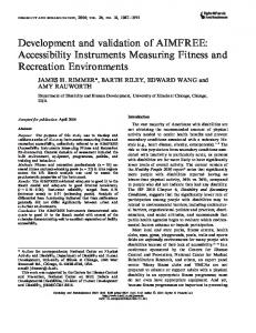
1. INTRODUCTION The need to design of present specialized tool arises from the application of the assembled engine. The products include diesel engines, irrigation pump sets, and diesel generating sets. These engines are used in agricultural machinery, construction and material handling machinery, marine applications and military applications. A detailed survey on the shop floor reflected the need of this tool on the assembly station of SL-90 engine. In the design phase present drawings gave following dimensions:
Figure 1: Top & Front View of Cylinder Head
In next step the calculations of the net force required for compressing the springs are carried out in following manner as discussed below: Spring material: EN47/ASTM 6150 Composition: 50Cr V4, Flat spring steel, high carbon, oil tempered hard drawn. Spring stiffness: (K)K = Force/Deflection. From the data available, Inner Spring Stiffness is Kinner = 8.03 N/mm & Outer Spring Stiffness is Kouter = 18.36 N/mm. Net deflection δ of the Inner spring: 16.7mm & Net deflection (δ) of outer spring: 21.35mm. No. of springs used = 4. Two springs are used together in parallel i.e. 1 set of inner and outer spring together as F = F1 + F2 (springs in parallel); F1 and F2 are forces exerted by outer and inner springs respectively. Inter national Jour nal of Manufacturing Science and Engineering • Inter national Science Press • Vol. 2 • No. 1 • Januar y-June 2011
54
Deulgaonkar Vikas Radhakrishna, Shivang Bhatnagar, Ashish Karve and Varun Kelkar
F = (K1 * d1) + (K2 * d2) Where, K1 = Stiffness of outer spring, K2 = Stiffness of inner spring, δ1 = Deflection of outer spring, δ2 = Deflection of inner spring. Substituting the values,
Net volume of remaining MS = 3720 – 80.32 = 3639.68 cm
3
Mass of remaining MS; Density = Mass/Volume Mass = 3639.68 * 7.85 = 28.571 Kg = 280.28 N Calculation of safe diameter of the pillar: The design of the support column is carried out as under
F = (18.36 * 16.7) + (8.03 * 21.35) = 306.612 + 171.441 = 478.053 N ~ 48kg Pneumatic cylinder bore diameter db calculations: Available air pressure: Pmax = 7kg/cm2 and Pmin = 5 – 2kg/cm2 F = P * A = 48.73 = (3 * 10–2) * (Π/4) * db2 d b2 = 2068.165 d b = 45.48mm ~ standard bore diameters: 32, 40, 50, 60, 80
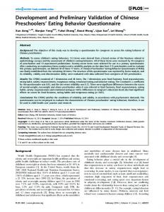
Material: MS Considering moment about A: ∑ M a = 0 (Clockwise = +ve) 2xRb × 400 = 348.95 × 200 i.e. Rb = 87.2375 N = Rd Considering moment about B: = +ve)
∑M
b
= 0 (Clockwise
2xRa × 400 = 348.95 × 200 i.e. Ra = 87.2375 N = Rc Assuming diameter of column = 30mm for initial analysis and Factor of safety (F.O.S) = 1.5
Available: 80mm Hence pneumatic cylinder of make, FESTO: DCV– 80 (bore diameter) –160(stroke) –PPV – A is selected. 2. DESIGN OF PLATES, COLUMNS, LOCKING MECHANISM
Π/4) * d2 = 706.85 mm2 Theoretical yield strength of MS = 250MPa A
r
e
a
o
f
c
o
l
u
m
n
=
(
Selection of safe diameter Force/Area = Syt /F.O.S = {(87.2375/9.81)}/706.85 = Syt /1.5 Syt = 0.018 kg/mm2 i.e.0.018 kg/mm2