World Electric Vehicle Journal Vol. 6 - ISSN 2032-6653 - © 2013 WEVA Page
Page 0364
EVS27 Barcelona, Spain, November 17-20, 2013
Development and Series Application of a Vehicle Drivetrain Observer Used in Hybrid and Electric Vehicles Dr. Gunther Götting 1, Markus Kretschmer 2 1
Robert Bosch GmbH, Postfach 30 02 40, 70442 Stuttgart,
[email protected]
Abstract This paper introduces the development and calibration process of a vehicle drivetrain observer used in hybrid and electric vehicles for active damping control (ADC) and for the improvement of the electric machine’s rotor angle signal quality. This approach starts with creating an overall vehicle model that includes the electric machine, the transmission, side shafts, the tires and the vehicle body. For control engineering purposes, that multi-order-model is then reduced into a two-mass-oscillator which can be easily described in state-space form. Using this reduced drivetrain model and applying a Luenberger observer approach, not only the signal quality of both the instrumented rotor angle and the speed of the electric machine can be improved considerably but also the oscillation dynamics of this vehicle drivetrain can be estimated. If not compensated during vehicle operation, drivetrain oscillations might lead to increased drivetrain wear, NVH issues and limited ride comfort; therefore, the oscillation speed is very important in computing an active damping torque that is to compensate drivetrain oscillations. Calibration of the vehicle drivetrain observer is done using specific vehicle test data that are fed into a standalone calibration tool identifying the parameters of the vehicle drivetrain as well as the Luenberger feedback vector. Based on these data, a proper active damping control application is set-up and verified in various vehicle tests and to lead to the calibration finally to the application in several hybrid and electric vehicle series projects (e.g. Peugeot 3008 HYbrid4). Keywords: active damping control, hybrid vehicles, electric vehicles, observer, drivetrain dynamics
1
Introduction
Hybrid (HEV) and electric vehicles (EV) do show a quite different vehicle drivetrain setup compared to conventional, combustion-enginedriven-only vehicles. Electric vehicles and several hybrid vehicles usually lack a launch element like a friction clutch or a torque converter which prevents the combustion engine from stalling during vehicle launch.
When launching a HEV or an EV from standstill using the electric machine, there is no need for a friction clutch since an electric machine is able to provide torque from zero speed already. In this case however, torque excitations on a vehicle drivetrain that does not include some sort of launch element result in e-machine speed oscillations that not only limit ride comfort but also tend to significantly increase drivetrain wear. To provide a proper electric machine torque, the machine’s rotor angle has to be known very
EVS27 International Battery, Hybrid and Fuel Cell Electric Vehicle Symposium
1
Page 0365
World Electric Vehicle Journal Vol. 6 - ISSN 2032-6653 - © 2013 WEVA Page
accurately in computing the phase currents to setup the machine torque. This paper introduces a control engineering approach that uses a simplified vehicle drivetrain model within a Luenberger observer to both estimate drivetrain oscillations and improve the signal quality of the measured rotor angle of the electric machine. I.e. by using this engineering approach (1) the positioning angle quality is improved leading to an improved torque and current control of the electric machine and (2) the drivetrain oscillations can be estimated which are necessary to compute an active damping torque compensating such drivetrain oscillations. Calibration of the drivetrain observer model is done using vehicle test data (e.g., electric machine torque and speed) and feeding it into a standalone parameter identification tool that computes drivetrain and observer feedback parameters. Applying these parameters into the electric machine’s torque and current control loop and properly calibrating the active damping control, drivetrain oscillations can be reduced considerably while improving ride comfort.
2
Vehicle Drivetrain Dynamics
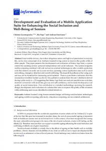
A vehicle drivetrain consists of several mechanical elements (e.g. engine/electric machine, transmission, differential gearbox, side shafts, tires, …) which all introduce its respective characteristics (e.g. inertia, stiffness) into the overall drivetrain. Based on these drivetrain parts and elements, it might be possible to come up with a very sophisticated simulation model of a vehicle drivetrain. Such a multi-order drivetrain model, however, is too complex to be used in real-time software applications controlling an electric machine. Owing to this fact, the vehicle drivetrain needs to be modeled differently without neglecting dominant drivetrain dynamics. Using an electric axle drive as a reference vehicle powertrain, Figure 1 shows how to reduce model complexity of a vehicle drivetrain model leading to a so called two-massoscillator. The dynamics of a rotational twomass-oscillator can be represented by applying the torque equilibrium for inertias J1 and J2 Eq. (1) where TEm indicates electric machine torque acting on inertia J1 while TLoad represents the drag or load torque exerted on inertia J2 (being the equivalent of vehicle mass plus wheel inertia).
TEm, Des J1 Rotor k Rotor c Rotor k c Wheel
Wheel
TLoad J 2 Wheel k Wheel c Wheel k c Rotor
(1)
Rotor
Figure 1: Vehicle Drivetrain Modeling
Parameters c and k are the corresponding stiffness and damping coefficients of the reduced drivetrain model. Indices ‘Rotor’ and ‘Wheel’ indicate angle , rotational speed and rotational acceleration of inertias J1 and J2, respectively. It might be noted here, that most vehicle drivetrains can be described using such a reduced two-massoscillator model.
3
Torque and Current Control
In normal drive operation, the electric traction drive of an EV/HEV is operated in torque control mode, i.e. the vehicle manager commands a desired torque, derived from the accelerator pedal. In recent years, permanent magnet synchronous machines (PMSM) are widely used for this application. This machine type requires an accurate rotor angle signal to provide a proper torque output by field oriented control (FOC) [1]. The electromagnetic torque TEm,Des can be derived from the d/q components of the stator current in the field oriented reference system as shown in Eq. (2). Remark: Electrical values are given in rms values, here as well as in the following. TEm, Des 3 p I q Ψ PM I d Ld Lq (2) The corresponding voltage equations are given in Eq. (3).
dI d Lq I q dt dI q U q Rs I q Lq Ld I d Ψ PM dt U d Rs I d Ld
EVS27 International Battery, Hybrid and Fuel Cell Electric Vehicle Symposium
(3)
2
World Electric Vehicle Journal Vol. 6 - ISSN 2032-6653 - © 2013 WEVA Page
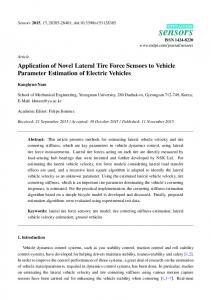
An error in the rotor angle directly influences the direction of the field oriented reference system and therefore detunes the direction of the controlled stator current phasor compared to its desired value. Figure 2 demonstrates how a given angle error of the stator current phasor IStator is propagated to a torque error. 400
400
Current Torque
0 25
30 0
350
300
0 40 25 0
30 0
250
400
40 0
0 20
300
OP1 20 0 30 0
350
300
15 0
250
25 0
20 0
40 0
OP2
200
angle error
30 0
200
IStator@OP1
15 0
15 0
0 20 10 0
150
150
iq qin/ A Iq / A, U V
20 0
10 0
100
IStator@OP2
100
10 0
100
50
50
0 -400
50
-350
-300
OP1 -250
20 0
50
30 0
40 0
50
-200
UStator@OP1 -150
-100
-50
0 0
in A Id / iA, Ud / V d
Figure 2: Angle error of stator current phasor and resulting torque error of a typical traction drive PMSM for different operating points (OP1 and OP2)
It is obvious, that the effect of an angle error on the resulting torque error is dependent on the operating point (OP). If the drive is operated in the base speed region following the maximum torque per ampere curve (MTPA), see e.g. [2], an angle error of 5°el. as shown in Figure 2 results in a torque error < 1% (OP1). Compared to this, in the field weakening area, the same angle error leads to an increased torque error of about -7 … +10% (OP2). Additionally, a detuned current phasor results in a detuned voltage phasor. This is demonstrated in
Page 0366
Figure 2, where the resulting voltage phasors are shown for the three different current phasors of OP1, calculated from Eq. (3). From a control point of view, this effect can be seen as a disturbance voltage, dependent on the angle error. In actual traction drive applications, the rotor angle is usually measured by a high resolution sensor system like e.g. a resolver (resolution: ≤ 1 °el.). In addition, depending on the vehicle setup, also a digital sensor system featuring a quite low angle resolution may be used (resolution: 15 … 60 °el.). In the latter case, the sensor output cannot be used directly but its resolution must be refined by adequate extrapolation algorithms. However, independent of the sensor system in use, the measured angle signal is disturbed by noise and affected by mounting and production tolerances, which, in turn, might result in corrupted phase currents as mentioned above. This introduces an additional torque ripple to the drivetrain and might even increase the drivetrain oscillations. Earlier investigations [3] have shown, that the overall performance of the torque control can be significantly improved, when the field angle used for the FOC is the output of an adequate state observer instead of directly using the sensor signal. Figure 3 shows a block diagram of the resulting torque control loop with the field oriented current controller including an observer and the physical system consisting of the inverter, the electric machine and the mechanical drivetrain. Since the observer structure is based on a mechanical model of the drivetrain, see chapter 4, it delivers besides the rotor angle additional internal state variables as well as the wheel and the rotor speed which can be used to implement an active damping control. It might be noted here that the ‘hat’ symbol ^ denotes an estimated number.
Figure 3: Block diagram of torque control loop using an observer for provision of proper rotor angle and internal drivetrain variables for active damping control
EVS27 International Battery, Hybrid and Fuel Cell Electric Vehicle Symposium
3
World Electric Vehicle Journal Vol. 6 - ISSN 2032-6653 - © 2013 WEVA Page
angle / °el.
rotor angle sensor angle observer angle
t/s
Figure 4: Comparison of physical rotor angle, raw signal of the low resolution sensor and output of an angle observer
If a low resolution angle sensor is used, the observer can help to reduce the angle error during extrapolation time, i.e. the time interval between two sensor pulses. In Figure 4, the output of an angle observer is compared to the raw signal of a low resolution digital sensor system, here without extrapolation, and the physical rotor angle. Obviously, the observer signal can follow the physical angle quite well, though using a low resolution sensor as feedback input. For best results it is of particular importance to carefully adapt the structure and the internal parameters of the observer to the vehicle drivetrain, as will be shown in chapter 5. In case of a high resolution angle sensor, the maximum angle error is usually quite low. Nevertheless, the raw signal of the sensor is affected by periodic and stochastic disturbances caused by mounting tolerances, signal processing and measurement noise. This, in turn, leads to disturbances on the measured field oriented current as well as on the output voltage of the current controller, as mentioned above. without observer
Page 0367
Evidently, the current ripple can be clearly reduced by using the observer output instead of the raw signal. Since the observer is able to improve the quality of the angle signal, the disturbance voltage which results from sensor noise and acts on the output voltage of the current controller can be eliminated.
4
Drivetrain Observer and Active Damping Control
The two-mass-oscillator model introduced in chapter 2 sets the basis for computing the oscillation speed Osc Rotor Wheel
(4)
of a vehicle drivetrain. Using Eq. (1) and applying an electric machine torque of TEm,Des = 50 Nm, TLoad = 0 Nm, J1 = 0.02 kgm2, J2 = 2.0 kgm2, c = 100 Nm/rad and k = 0.1 Nms/rad, the rotational speeds Rotor and Wheel as well as the oscillation speed Osc can be computed (Figure 6).
with observer
Iq,Des
150 120
Figure 6: Drivetrain oscillations
90
I in A
60 30 0 -30 -60
Id,Des
-90 -120 0
1
2
3
4
t in s
Figure 5: Performance of current control with HFdisturbances on rotor angle signal, without and with observer
Figure 5 shows a measurement result of a field oriented current control with a high resolution angle sensor. While for t < 2.2 s the field angle is directly derived from the raw signal of the sensor, for t > 2.2 s an adequate observer is used for this task.
Looking up the torque control loop described earlier (Figure 3), it can be noticed that the positioning angle of the electric machine and the desired torque are the only input signals fed into the drivetrain observer – the oscillation speed Osc , however, cannot be measured without proper wheel speed information. To compute oscillation speed, therefore, some sort of estimation algorithm is required to provide the oscillation speed estimation Osc using the positioning angle, the desired torque and the two-mass-oscillator model. For this purpose, a so called Luenberger observer is used to estimate the necessary system state
EVS27 International Battery, Hybrid and Fuel Cell Electric Vehicle Symposium
4
World Electric Vehicle Journal Vol. 6 - ISSN 2032-6653 - © 2013 WEVA Page
information required to apply an active damping torque.
4.1
The Luenberger Observer
A Luenberger observer [3, 4] combines a model of a real-world process (e.g. a vehicle drivetrain) with one or several internal measurement signals derived from the real-world process ( y Rotor ) leading to model state estimates which cannot be measured (Figure 7). From control engineering textbooks, one can derive the state-space representation of a linear, time-invariant system shown in Eq. (5): x A x B u y C x D u
(5)
The matrices and vectors are defined as follows: x … state vector x … time derivative of state vector x A … system matrix B … input matrix C … output matrix D … feedforward matrix u … input signal(s)/vector y … output signal(s)/vector
Page 0368
ˆOsc . The former estimate can be used to improve torque and current control, the latter is used to compute a proper active damping torque.
4.2
The Active Damping Control
To compensate drivetrain oscillations (Figure 6), the electric machine torque acting on a vehicle drivetrain needs to be modulated. I.e. depending on the desired torque TDes derived from the driver’s input on the accelerator (1) the oscillation speed ˆ has to be computed and, based on this Osc
number, (2) a so called damping torque TDmp is to be created and subtracted from TDes leading to the (3) electric machine torque TEm,Des (Figure 8). The damping factor kDmp converts the oscillations speed ˆOsc into the damping torque TDmp, see also [6, 7]. Note, that kDmp might vary depending on input torque TDes and electric machine speed ˆRotor .
Figure 8: Creating Damping Torque TDmp
Applying Eq.(5) on the Luenberger observer, the state-space equations become:
ˆ ˆx Bˆ u L y ˆy ˆx A
ˆy Cˆ ˆx
(6)
Note, that L is the so called Luenberger feedback vector (or matrix) which is necessary to “connect” the observer with the real-world process via the estimation error y ˆy . Figure 9: Active Damping Control (ADC) Operation
Figure 7: Luenberger Observer
This observer structure then provides estimates of the rotor angle ˆRotor and the oscillation speed
Applying the same parameters that have led to the results depicted in Figure 6 and setting kDmp = 0.1 Nms/rad, drivetrain oscillations can be compensated significantly (Figure 9). Since a vehicle drivetrain features spring elements (e.g. drive shafts) any change in torque acting on the drivetrain leads to a change of the relative motion between the electric machine and the vehicle’s wheels. Therefore, the speed peak at t ≈ 0.02 s cannot be fully compensated – it is rather the effect of applying tension on the vehicle drivetrain.
EVS27 International Battery, Hybrid and Fuel Cell Electric Vehicle Symposium
5
World Electric Vehicle Journal Vol. 6 - ISSN 2032-6653 - © 2013 WEVA Page
5
Page 0369
Identifying Vehicle Drivetrain Parameters
Knowing a physical representation of a vehicle drivetrain which contains four parameters only (J1, J2, k, c) to model the two-mass-oscillator, one needs to find correct parameter settings for vehicle applications. To provide a quick and easy way to identify such drivetrain parameters, a standalone software tool was developed allowing calibration engineers to efficiently do both testing and classification of identified drivetrain parameters without having to use MATLAB® or other available state-of-the-art tools. Figure 11: IPE-ADC Standalone Tool
5.1
Parameter Identification Tests
Control engineering textbooks introduce several test signals resulting in a system response which can be used to identify unknown system parameters. To investigate drivetrain parameters, the test vehicle whose drivetrain dynamics has to be identified is placed on a flat, even road. Then an electric machine torque step is exerted on the drivetrain measuring the electric machine speed (Figure 10).
Comparing the results of the initial vehicle test (Figure 10) with the identification results shown in (Figure 12), it can be noted that the IPE-ADC software provides sufficient two-mass-oscillator parameter estimation for modeling a vehicle drivetrain. By looking up the ratio between torque input (40 Nm) and the first speed peak (≈ 200 rpm), one can also get a first hint on how to set-up the damping factor kDmp (Figure 8). After setting up both the model parameters and the Luenberger observer, the active damping control and the observer’s angle estimation algorithms – providing ˆRotor – have to be tested in everyday driving and in several specific vehicle tests.
Figure 10: Drivetrain Identification Test
These torque and speed data are then fed into the standalone software tool IPE-ADC (Figure 11). For each of the four drivetrain parameters a specific search space is defined setting the basis for identifying J1, J2, c and k. Besides the identification routine, IPE-ADC also provides the numbers for the Luenberger feedback vector L. Once the proper parameters have been estimated and the observer feedback vector is determined, a software calibration file is created which can be easily used to enable proper active damping control operation of the inverter software.
Figure 12: Drivetrain Identification Results
EVS27 International Battery, Hybrid and Fuel Cell Electric Vehicle Symposium
6
World Electric Vehicle Journal Vol. 6 - ISSN 2032-6653 - © 2013 WEVA Page
6
Vehicle Testing
To validate active damping control operation and the signal quality of the estimated electric machine rotor angle ˆRotor , various vehicle tests need to be performed. This chapter presents test results that feature some specific vehicle tests: Vehicle Launch Torque Load Changes Sidewalk Climb
6.1
Vehicle Launch
In chapter 5.1, the identification process to investigate drivetrain parameters was introduced. One could notice significant speed oscillations caused by an e-machine torque step and the dynamics of the vehicle drivetrain (Figure 10). In everyday driving however, such torque steps do not occur – the vehicle control unit rather converts the driver’s input (via the accelerator) into a pre-filtered set-torque TDes that the electric machine is to deliver. But even if the desired settorque is created by some sort of filtering algorithm, the vehicle drivetrain still represents an underdamped system with only little damping.
Figure 13: Vehicle Launch without ADC
Figure 14: Vehicle Launch with ADC
Page 0370
Therefore, there is still the necessity to apply a proper active damping control to establish a smooth driving behavior. Figure 13 and Figure 14 compare a vehicle launch test without and with ADC operation active, respectively. The test result without ADC shown in Figure 13 demonstrates how the vehicle drivetrain is excited to oscillations by torque ramps, which can be seen from the rotor speed signal. Due to the low physical damping, these oscillations decrease very slowly, which leads to a long-lasting disturbance of driving comfort. However, when the vehicle launch is performed with activated ADC (s. Figure 14), the rotor speed signal shows a very smooth behavior, indicating that drivetrain oscillations are well damped by the interaction of the damping control. It is remarkable, that in this situation only a very low amount of damping torque is sufficient to prevent the drivetrain from oscillating. To achieve this excellent performance, it is indispensable to carefully tune the observer parameters to the specific vehicle drivetrain, as shown in chapter 5.
6.2
Torque Load Changes
In vehicle tests featuring torque load changes, the driver applies and releases the accelerator repeatedly; leading to significant torque inputs (Figure 15, Figure 16). When releasing the accelerator, it might happen that the electric machine is commanded into regeneration mode, i.e. the electric machine torque becomes negative (while driving forward). Such a sign change in electric machine torque not only leads to a significant change in vehicle acceleration, it also results in a tooth flank contact change because of transmission play. Since the two-mass-oscillator model does not feature such transmission play, it is vital to test whether or not the observer can cope with that kind of model uncertainty. As seen from Figure 15, the driving situation specified above leads to significant drivetrain oscillations, again to be detected by the oscillations in the rotor speed signal. Figure 16 shows the test results for the same driving situation, this time with ADC turned on. Right after a sign change in torque (t ≈ 145 s, t ≈ 146.3 s) a significant peak in active damping torque TDmp can be noticed. This torque peak is caused by releasing the drivetrain spring (which basically consists of the vehicle’s side shafts) and running the drivetrain through the transmission play. Obviously, the proposed active damping control approach can deal very efficiently with these effects.
EVS27 International Battery, Hybrid and Fuel Cell Electric Vehicle Symposium
7
World Electric Vehicle Journal Vol. 6 - ISSN 2032-6653 - © 2013 WEVA Page
Page 0371
Figure 15: Torque Load Changes without ADC
Figure 17: Sidewalk Climb without ADC
Figure 16: Torque Load Changes with ADC
Figure 18: Sidewalk Climb with ADC
6.3
Sidewalk Climb
The sidewalk climb is probably one of the most challenging tasks for both torque/current control and active damping control application: The vehicle’s driving wheels are placed right at a sidewalk; then, the accelerator is applied and the electric machine is to provide enough torque (here: > 150 Nm) while being operated at very low rotational speeds such that the vehicle’s driving wheels “crawl up” the sidewalk, basically lifting up half the vehicle weight (Figure 17, Figure 18). This exerts not only significant mechanical wear on the drivetrain but also a considerable thermal stress on the inverter itself. When performing this test without ADC, the sidewalk climb process goes along with strong drivetrain oscillations, s. Figure 17. An activated damping control can clearly reduce these oscillations, resulting in a smoother and more comfortable behavior, as shown in Figure 18.
7
Conclusions
This paper provides some insight on the necessity to improve the signal quality of rotor angle measurements used in the torque and current control of hybrid and electric vehicles as well as the need to efficiently compensate vehicle drivetrain oscillations. Since such oscillations do not only result in considerable wear but in ride comfort issues as well, there is an essential interest in creating a proper electric machine control that leads to both smooth and sportive driving of hybrid and electric vehicles. The proposed observer based solution turns out to be very successful in improving the quality of the rotor angle signal, used for the FOC, as well as in estimating an adequate oscillation signal as input for an active damping control. For best results, the tuning of the observer parameters can be precisely done with the help of the presented calibration tool. The control engineering approach presented here, has found its way in several current and future hybrid and electric vehicle series projects (e.g. Peugeot 3008 HYbrid4).
EVS27 International Battery, Hybrid and Fuel Cell Electric Vehicle Symposium
8
World Electric Vehicle Journal Vol. 6 - ISSN 2032-6653 - © 2013 WEVA Page
Page 0372
References [1]
S. Macminn and T. Jahns, Control Techniques for Improved High-Speed Performance of Interior PM Synchronous Motor Drives, IEEE Trans. on Ind. Appl., Vol. 27, No. 5, Sept/Oct. 1991
[2]
B. Cheng, T. Tesch, Torque Feedforward Control Techniques for Permanent-Magnet Synchronous Motors, IEEE Trans. on Ind. Appl., Vol. 57, No. 3, March 2010
[3]
G. Götting, Ermittlung der Rotorlage zur Regelung einer PSM in Hybird- und Elektrofahrzeugen, AUTOREG 2011
[4]
Norman S. Nise, CONTROL SYSTEMS ENGINEERING, ISBN 0-471-36601-3, John Wiley & Sons, 2000
[5]
Otto Föllinger, Regelungstechnik, ISBN 37785-2336-8, Heidelberg, Hüthig, 1994
[6]
M. Menne, R. W. De Doncker, Active Damping of Electric Vehicle Drivetrain Oscillations, Proceedings of Power Electronics and Motion Control Conference (EPE-PEMC) 9, Kosice, 2000
[7]
G. Götting, R. W. De Doncker, Comparison of Algorithms for Suppression-Control of Drivetrain-Oscillations in Electric Vehicles, Proceeding of Electric Vehicle Symposium (EVS) 19, Busan, 2002
Authors Gunther Götting holds both a diploma and a Ph.D. in Electrical Engineering from RWTH Aachen, Germany. He is a senior expert in electric machine control and also works in the fields of observer development and active damping control. Gunther Götting might be contacted via
[email protected] Markus Kretschmer holds a diploma in Mechanical Engineering from the University of Stuttgart, Germany. His fields of work include active damping control, observer and control engineering applications as well as vehicle tests. Markus Kretschmer might be contacted via
[email protected]
EVS27 International Battery, Hybrid and Fuel Cell Electric Vehicle Symposium
9