Separations Area, Savannah River. Site, South Carolina. J. M. Rine 7 R. C. Berg 7 J. M. Shafer 7 E. R. Covington 7 J. K. Reed 7 C. B. Bennett. J. E. Trudnak.
Cases and solutions
Development and testing of a contamination potential mapping system for a portion of the General Separations Area, Savannah River Site, South Carolina J. M. Rine 7 R. C. Berg 7 J. M. Shafer 7 E. R. Covington 7 J. K. Reed 7 C. B. Bennett J. E. Trudnak
Abstract A methodology was developed to evaluate and map the contamination potential or aquifer sensitivity of the upper groundwater flow system of a portion of the General Separations Area (GSA) at the Department of Energy’s Savannah River Site (SRS) in South Carolina. A Geographic Information System (GIS) was used to integrate diverse subsurface geologic data, soils data, and hydrology utilizing a stack-unit mapping approach to construct mapping layers. This is the first time that such an approach has been used to delineate the hydrogeology of a coastal plain environment. Unit surface elevation maps were constructed for the tops of six Tertiary units derived from over 200 boring logs. Thickness or isopach maps were created for five hydrogeologic units by differencing top and basal surface elevations. The geologic stack-unit map was created by stacking the five isopach maps and adding codes for each stack-unit polygon. Stackedunits were rated according to their hydrogeologic properties and ranked using a logarithmic approach (utility theory) to establish a contamination potential index. Colors were assigned to help display relative importance of stacked-units in preventing or promoting transport of contaminants. The sensitivity assessment included the effects of
Received: 1 April 1997 7 Accepted: 4 November 1997 J. M. Rine (Y) 7 J. M. Shafer 7 E. R. Covington J. E. Trudnak Earth Sciences and Resources Institute, University of South Carolina, Columbia, SC 29208, USA Tel: c1-803-777-7792 Fax: c1-803-777-6437 e-mail:jrine6esri.esri.sc.edu R. C. Berg Illinois State Geological Survey, 615 East Peabody, Champaign, IL 61820, USA J. K. Reed 7 C. B. Bennett Westinghouse Savannah River Company, 742-A, Aiken, SC 29808, USA
surface soils on contaminants which are particularly important for evaluating potential effects from surface spills. Hydrogeologic/hydrologic factors did not exhibit sufficient spatial variation to warrant incorporation into contamination potential assessment. Development of this contamination potential mapping system provides a useful tool for site planners, environmental scientists, and regulatory agencies. Key words Contamination potential 7 Leakance 7 Stacked-units 7 GIS 7 Isopachs
Introduction The US EPA (1993) defines aquifer sensitivity/contamination potential as “a measure of the ease with which a contaminant applied on or near the land surface can migrate to an aquifer. It is a function of the intrinsic characteristics of both the geologic materials comprising the aquifer as well as overlying saturated and unsaturated materials. It is independent of land use and the types of contaminants introduced.” This paper describes the initial phase of a multi-year investigation to develop a method utilizing Geographic Information Systems (GIS) to evaluate and map the contamination potential of the upper groundwater flow system at the Savannah River Site (SRS) in southwestern South Carolina (Fig. 1). In this initial phase, the objective was to apply the contamination-potential evaluation methodology to mapping a portion of the General Separations Area (GSA) at SRS. The GSA was selected as the area for a pilot study because of plentiful subsurface well data. Numerous wells have been drilled within the GSA, because of the waste burial sites located there and the potentially adverse contamination problems resulting from these sites. The upper groundwater flow system at the SRS corresponds to the regulatory uppermost aquifer defined by state hazardous and mixed waste permit provisions. For the purposes of this study, they encompass
Environmental Geology 35 (4) September 1998 7 Q Springer-Verlag
263
Cases and solutions
Fig. 1 Map showing general location of the DOE’s Savannah River Site (SRS), within which is the oval-shaped study area, the General Separations Area (GSA)
264
Environmental Geology 35 (4) September 1998 7 Q Springer-Verlag
the geologic units above a regionally confining hydrogeologic unit, the Crouch Branch Confining unit of Aadland and others (1995), see Fig. 2. Therefore, this interval is of significant importance from a regulatory perspective and warranted initial assessment. The methodological approach described herein, however, is also applicable to evaluate contamination potential of deeper subsurface units, as well as shallower units within the upper groundwater flow system. Determination of the sensitivity, or contamination potential, of water-bearing geologic units has become a national priority (Soller and Berg 1992; US EPA 1993). When planning for future land use (especially when determining sites for facilities that handle hazardous substances and conduct waste disposal operations), determining the likely extent of groundwater contamination problems, developing a regional/local groundwater monitoring plan, or helping to screen for potential ’hot spots’ of contamination, the natural susceptibility of groundwater systems to contamination should be considered. Several factors Fig. 2 Chart correlating hydrostratigraphic units used in this study with recognized hydrostratigraphic units from southeastern South Carolina coastal plain from Aadland and others (1995)
Cases and solutions
strongly influence the potential for any water-bearing geologic materials to become contaminated. The factors used to assess contamination potential for this study include the lithology of the more permeable aquifer units, the lithologies and thickness of intervening confining units/aquifers, surface soil properties (e.g., organic matter content, macropore development, infiltration rates, etc.), and recharge/discharge relationships. The integration of this diverse information is possible using a three-dimensional geologic mapping approach (i.e., stack-unit mapping) and GIS technology to construct mapping layers. This paper describes several new innovations and components of geologic mapping for contamination potential assessment. (1) This is the first time that a stack-unit mapping approach, developed in the Midwest for mapping glacial sediments, has been used to delineate geologic materials in a coastal plain environment. (2) The technique was used for a relatively small area (8–10 km 2). It has previously been applied only for regional assessments (such as counties or an entire state). (3) The mapping program was designed so that additional data or reinterpretations could modify the results at any time. (5) Finally, this is the first time that the approach has used to construct a stack-unit map of units extending deeper than 30 m into the subsurface. The maximum thickness of stack-units in this study exceeded 75 m.
Background Historical background The SRS is a Department of Energy (DOE) facility occupying a 790-km 2 area of southwestern South Carolina bordering the Savannah River and the Georgia state line. Beginning in the 1950s, the SRS mission was to produce special nuclear materials primarily for national defense. Production of nuclear materials has since ceased, but processing of nuclear waste materials and byproducts for reuse or disposal continues, especially within the area of study, the GSA. Nuclear and non-nuclear waste storage facilities in the form of burial sites, seepage basins and storage tanks are also present within the GSA. Geology of the study area The SRS and the GSA are underlain by Tertiary to Cretaceous aged sediments of the Atlantic Coastal Plain. The predominant lithologies present within the Coastal Plain sequence beneath SRS consist of poorly consolidated sand, muddy sand, and mud with patchy occurrences of calcareous sediments. The Tertiary age sediments, which contain the upper groundwater system addressed in this study, are interpreted to range from early Paleocene to Miocene (?) in age (Fallaw and Price 1995; Aadland and others 1995). Synoptic descriptions of the geologic units involved in this study are presented in Fig. 3. These descriptions are taken from Aadland and others (1995).
Fig. 3 General descriptions of hydrostratigraphic units used in this study of the GSA at the SRS. Descriptions derived from Fallaw and Price (1995), Aadland and others (1995), and Nystrom and others (1986)
Description and location of the study area The SRS is approximately 160 km northwest from the Atlantic Coast and 40 km southeast of the Fall Line separating the Piedmont from the Upper Atlantic Coastal Province. The study area (GSA) is located in the central portion of the SRS and exhibits low to moderate relief. The GSA is drained by several unnamed perennial streams as well as Upper Three Runs Creek to the north and Fourmile Creek in the south (Fig. 4a). Previous contamination-potential mapping studies Determination of aquifer sensitivity across the USA has been conducted in response to the need for more detailed geologic information to support regional land-use planning and resource-based decision making. Establishment of the three-dimensional framework of geologic materials and delineating aquifer and nonaquifer materials have
Environmental Geology 35 (4) September 1998 7 Q Springer-Verlag
265
Cases and solutions
Fig. 4a–f Surface elevation maps of the five hydrostratigraphic units analyzed in this study and the surface of the basal confining unit (Ellenton). Surfaces are based on data from 262 wells (core and geophysical logs). a shows the topography of the study area along with locations of wells (dots), roads, and surface drainage pattern. Upper Three Runs Creek occupies the deeply incised valley in the northern portion of the study area and Fourmile Creek occupies the moderately incised valley in the south. Topography is based on 1 : 24000 USGS Digital Line Graph (DLG) hypsography. b–f show affects of erosion by Upper Three Runs Creek and its feeder stream valleys
been essential to understanding the sensitivity of groundwater to land use. For example, statewide and regional contamination potential maps have been used extensively in Illinois since the mid-1980s for purposes of locating sites for future landfills, prioritizing areas for groundwater monitoring, selecting candidate areas for development of a low-level radioactive waste disposal facility, and studying the potential effects of agricultural chemicals on shallow groundwater quality (Berg and others 1984; Shafer 1985; Keefer and Berg 1990; Keefer 1995). The Illinois methodology applied in the glacial sediments of the midwest is the same methodology as applied in this study to the coastal plain sediments of South Carolina. In addition to sensitivity studies in Illinois, vulnerability of drift aquifer systems has also been determined for Michigan (Passero and others 1989; Lusch and others 1992), Iowa (Hoyer and Hallberg 1991), Wisconsin (Schmidt 1987), and Georgia (Trent 1992), and county groundwater vulnerability maps have been made in Indiana (e.g., Fleming 1994). 266
Environmental Geology 35 (4) September 1998 7 Q Springer-Verlag
One of the more commonly used methods for regionally assessing groundwater susceptibility in the USA is an approach called “DRASTIC” (Aller and others 1987). DRASTIC is an acronym for the seven factors considered in the method: Depth to water, net Recharge, Aquifer media, Soil media, Topography, Impact of the vadose zone media, and hydraulic Conductivity of the aquifer. A comparison study of DRASTIC with the Illinois method (same as this study) and the Wisconsin method of Schmidt (1987) was conducted by the US Geological Survey (Soller 1992) on twelve counties in Wisconsin, Illinois, Michigan, and Indiana. While no model was “seen as clearly superior to another” (Soller 1992, p. 32), the DRASTIC method was considered in many of the mapped counties to be “highly generalized” in comparison to the Illinois and Wisconsin techniques. The methodology described in this paper and used in Illinois is much different to that of the DRASTIC technique. In this study and in the Illinois method, factors such as depth to water, topography, and net recharge are not
Cases and solutions
considered important. The main difference, however, is that DRASTIC generalizes factors, such as aquifer media, soil media, and hydraulic conductivity, while the main objective of the methodology described in this paper is to delineate the heterogeneity and spatial distribution of these same factors.
A stack-unit map and derivative contamination potential map(s) were developed for the General Separations Area (GSA) at the SRS. Five lithologic/hydrostratigraphic intervals were characterized and mapped. Figure 3 summarizes these five hydrostratigraphic units and Fig. 2 correlates them with the hydrostratigraphic units published in Aadland and others (1995) as well as other stratigraphic studies of the region. The five intervals, comprising the upper groundwater flow system, from top to bottom are as follows: General methodology 1. Upland extends from the ground surface to top of the Tan Clay and includes the “Upland unit” or Altamaha The approach presented in this paper uses readily obtainFormation, Tobacco Road Sand, and the upper part of able geologic/hydrogeologic data and relies on estabthe Dry Branch Formation of previous studies (Aadlishing the geologic framework as a foundation for the land and others 1995; Fallaw and Price 1995). contamination potential assessment. To determine the 2. Tan Clay unit (confining zone) or “Twiggs clay lithocontamination potential of the upper groundwater flow facies” (Fallaw and Price 1995). system at the SRS, it was essential to map geologic mate- 3. Barnwell-McBean unit is between the Tan Clay and rials in three dimensions while paying particular attenGreen Clay intervals and includes a portion of the Dry tion to the lithology of the more permeable aquifer units, Branch Formation and the Clinchfield and Tinker forthe lithologies and thickness of geologic materials within mations (within the Santee Formation) of Fallaw and or surrounding the aquifers, hydraulic conductivities of Price (1995). aquifers and overlying/underlying confining units, soil 4. Green Clay unit (confining zone) is a fine-grained liproperties (e.g., organic matter content, macropore develthofacies within the Warley Hill Formation (Aadland opment, and other soil hydraulic properties), and reand others 1995). charge/discharge relationships. There are many more fac- 5. Congaree unit is a generally well sorted, fine- to tors which influence the potential for groundwater to becoarse-grained sand with pebbly zones common (Aadcome contaminated, such as topography, microclimate, land and others 1995). Unit includes the Fourmile and vegetative cover, depth to water, waste types and loadSnapp of Fallaw and Price (1995). ings, and waste disposal methods. However, measureThe lower boundary of the upper groundwater system is ment, delineation, and weighing of these factors is very the top of the “Ellenton Formation” of Siple (1967) or the difficult and expensive, and often yields misleading reCrouch Branch confining unit of Aadland and others sults (Soller 1992). (1995). The contamination potential model assembled for The integration of the foregoing information is best acthe GSA evaluates the potential for a contaminant to complished using a stack-unit mapping approach as a move downward through the above five units to the top foundation (Berg and Kempton 1988). A stack-unit map of the Ellenton. The hydraulic-head difference across the shows successions of geologic materials (or variations Ellenton is upward throughout the pilot-study area. Conwithin materials) in their order of occurrence (from top sequently, the top of the Ellenton is a logical choice to be to bottom), to a specified depth or boundary. Each disthe base of this contamination potential analysis. crete map area represents a unique succession of materials differentiated on the basis of lithology, thickness, absence/presence of units, hydraulic conductivity, or other Construction of top of unit material properties. The sensitivity of aquifers to contamination is evaluated elevation contour maps by rank ordering of the stack-unit successions after conElevation contour maps were constructed for the tops of sidering the spatial variability of geologic materials and their hydraulic conductivities and soil properties. For ex- the Tan Clay, Barnwell-McBean, Green Clay, Congaree Formation, and the Ellenton (Fig. 4b–f). The data consist ample, an aquifer mapped within an area of high conof hydrostratigraphic unit tops previously determined for tamination potential at the SRS may be overlain by the thickest accumulations of sand and gravel, minimal or no the GSA and supplemented with additional site-specific geologic data available from test-hole boring records, protection from either intervening or overlying finedown-hole logs, and surface exposures. Available subsurgrained materials, surface soils low in organic matter (low attenuation potential) and with high hydraulic con- face information decreases with depth. There were 246 ductivities, and location in a ’principal’ recharge area. In borings utilized to map the surface of the Tan Clay, 229 used to map the Barnwell-McBean, 122 used to map the contrast, an aquifer mapped within an area of low conGreen Clay, 120 used to map the Congaree Formation, tamination potential is probably protected by overlying and 28 used to map the surface of the Ellenton. fine-grained deposits, surface soils with higher organic The five elevation contour maps were contoured by hand matter content, and location in groundwater discharge at a contour interval of 3 m. Hand-contouring was conareas.
Environmental Geology 35 (4) September 1998 7 Q Springer-Verlag
267
Cases and solutions
sidered preferable over using a computerized contour package because erosion/deposition features which are common on these surfaces are generally more accurately rendered via a geologist’s interpretation. Particular care was exercised when contouring the Tan Clay and Barnwell-McBean maps and the Green Clay and Congaree Formation maps, respectively, because both clay units are generally less than 3 m thick. Therefore, the general placement of contour lines and linear trends of elevations was similar for the two sets of elevation contour maps. In addition to contouring the five maps, all elevation picks from bore-hole data points were scrutinized by evaluating how they fit with the trends of mapped contour lines. Deviant points (wells) were discarded and elevation contour lines on all five maps were modified to accommodate the removal of data points. Deviant data usually consisted of old well-log data not subject to quality assurance procedures at the time samples were described, as well as data determined to be of questionable interpretation by site geologists. Based on an evaluation of data density, the study-area boundary within the GSA was restricted to include only that portion where a significant density of data was available. The western and northwestern portions of the GSA are noticeably void of data and, consequently, were not mapped for this preliminary study. The five final elevation contour maps were manually digitized and then integrated with Arc/Infot software and projected to Universal Transverse Mercator (UTM) projection. Effects of erosion on development of elevation contour maps A major consideration regarding the elevation contour maps was the effect of erosion adjacent to Upper Three Runs Creek in the northern part of the study area (Fig. 4a). Erosion along Upper Three Runs Creek results in the subsequent decrease in elevation of the Upland interval, Tan Clay, Barnwell-McBean, and Green Clay, their exposure along the valley walls, and eventual absence of mapped units on the north side of the GSA study area. Maps were modified to account for the slope of this valley wall by using 1 : 24000 USGS digital line graph (DLG) hypsography (showing surface topography) to represent unit surfaces. The lowermost unit affected by erosion along Upper Three Runs Creek is the Congaree. DLG elevations were used to determine the top of the Congaree in the floodplain and the lower valley walls. The contour map for the underlying Ellenton was entirely done with subsurface data. Construction of unit isopach maps Machine-drawn isopach (thickness) maps or layers of the five units were produced using GIS capabilities. First, six contour line coverages were entered into topogrid interpolation method for the creation of Digital Elevation Models (DEM). Topogrid is based on the ANUDEM program developed by Michael Hutchinson (1988), and is specifically designed to produce hydrologically correct 268
Environmental Geology 35 (4) September 1998 7 Q Springer-Verlag
DEMs. Separate grids for each of the six data layers were generated. A 5-m resolution was chosen for each grid to capture the total detail. The Arc/Infot, GRID module was selected for further processing of grids with each of the isopach grids converted into Arc/Infot polygon coverages. The isopach “maps” or polygon layers created by this process have uniform values between “contour lines” and within polygons. In contrast, values between contour lines on a typical isopach map range from the low to high value of the immediately adjacent contour line. Elevations from vertically adjacent upper surfaces of the five elevation contour maps were subtracted to create the isopach or polygon layer maps for each of the five units. For example, the isopach map of the Upland interval was produced by subtracting elevations of the Tan Clay top contour map from the DLG of the land surface. It was important to derive machine-drawn isopach maps because previously undisclosed features were revealed. As much of this information as possible was retained. However, numerous artifacts from the subtraction process were a major problem due to minimal elevation differences between the Tan Clay and Barnwell-McBean and the Green Clay and Congaree, respectively. The machinedrawn isopach maps, therefore, often did not appear geologically plausible. Revised isopach maps were made of each unit by overlaying individual thickness points on the machine-drawn isopach maps and redrawing the maps. These new maps retained step trends of the original machine-drawn surface subtraction process, honored specific thickness data points, and incorporated obvious data trends. The resulting isopach maps integrated trends with geologic interpretation to produce more geologically sound representations of the thickness of each unit (Fig. 5). Selecting thickness intervals Intervals of 3 m thickness were initially selected in order to observe the thickness trends of each unit. Thickness contours were eventually simplified to reduce the complexity of the combined stack-unit geologic map and make it more readable. The isopach classes for the five units are: Upland interval: The isopach map for the Upland was divided into five thickness categories: absent, 0–6 m, 6–15 m, 15–30 m, and 1 30 m. Categories were determined based on the statistical distribution of data points within each range. Also, these ranges are commonly used for stack-unit mapping and evaluation of groundwater contamination potential in other regions (Berg and others 1984; Berg 1994). This thickness map clearly reflects erosion along Upper Three Runs Creek and Four Mile Creek (Fig. 5a). Tan Clay: The isopach map for the Tan Clay was divided into three thickness categories: absent, 0–3 m, and 1 3 m. Tan Clay is noticeably absent along Upper Three Runs Creek and in a banana-shaped area in the northeastern portion of the study area (Fig. 5b). Barnwell-McBean: The isopach map for the BarnwellMcBean was divided into three thickness categories based
Cases and solutions
Fig. 5a–c Interval thickness maps (isopachs) for each of the five hydrostratigraphic units analyzed in this study. Thickness maps were derived from subtracting the surface elevation map of the top of a unit from the surface elevation map of the immediately underlying unit. For example, the Tan Clay thickness was derived by subtracting the surface elevation map of the Barnwell/McBean from the Tan Clay (see Fig. 4b and c). Absent or thin areas at the tops of these maps are the result of erosion by Upper Three Runs Creek and its feeder stream valleys
on the number of specific data points within each range, ~15 m, 15–21 m, and 1 21 m. Thinning of the BarnwellMcBean along the valley wall of Upper Three Runs Creek is obvious (Fig. 5c). Green Clay: Similar to the Tan Clay, the isopach map for the Green Clay was divided into three thickness categories, absent, 0–3 m, and 1 3 m. It is absent along Upper Three Runs Creek due to erosion. A thickness between 0 and 3 m is most common for this unit (Fig. 5d). Congaree: The isopach map for the Congaree was divided into three thickness categories based on the number of specific data points within each range, ~24 m, 24–30 m, and 1 30 m. Thinning of the Congaree within the valley of Upper Three Runs Creek has been minimal. The unit actually thickens beneath the creek (Fig. 5e).
Development of the stack-unit map and a preliminary contamination potential map Creating the geologic stack-unit map The stack-unit map of geologic materials was created by stacking the five unit isopach polygon coverages together. Coded symbols or attributes were assigned to each polygon (closed contour interval) of each individual unit. Table 1 shows the 14 code symbols or attributes assigned to the thickness intervals present in the unit polygon coverages. The stack-unit map was then created by overlaying isopach coverages that resulted in one GIS layer with 470 polygons (Fig. 6). This process in GIS is known as a spatial join and is accomplished by an overlay procedure fundamental to GIS spatial analysis (ESRI 1993). The attributes for the polygons in the resulting stack-unit or polygon-overlay map consist of a composite of attributes from the unit maps.
Environmental Geology 35 (4) September 1998 7 Q Springer-Verlag
269
Cases and solutions
Table 1 Key to correlate attribute codes with unit and unit thicknesses for the General Separations Area unit
thickness (m)
code
Upland interval
0–6 6–15 15–30 1 30
u U Ub U*
Tan Clay
0–3 1 3
t T
Barnwell/McBean
~15 15–21 1 21
b B Bb
Green Clay
0–3 1 3
g G
Congaree
~24 24–30 1 30
c C Cb
When overlaying polygon coverages that are often unrelated to one another, the resulting polygon-overlay or stack-unit map is very complex because these coverages do not generally share common polygon boundaries. For instance, the edited stack-unit map of the GSA consists of 79 unique combinations of the original 14 unit thickness attributes with multiples of these attributes distributed over 470 separate polygons. The stack-unit map was edited to make it less complex by eliminating small polygons, called “sliver polygons.”Sliver polygons representing areas less than 1000 m 2 were eliminated automatically by an Arc/Infot process which dissolves a sliver polygon consisting of less than the specified area into the adjacent polygon with the longest border. (Care was taken not to eliminate a slice polygon supported by a data point.) Other small polygons were removed selectively by
270
Environmental Geology 35 (4) September 1998 7 Q Springer-Verlag
dissolving them into the most important adjoining polygon which bordered them. The criterion used to denote relative importance was based on perceived ability of a stack-unit combination to inhibit the vertical transport of contaminants. How this relative importance of stack-unit combinations was determined is described in the following section. The labeled stack-unit map is a useful tool for displaying geologic information on the map and is understandable once the user becomes familiar with the coding system (Fig. 6); however, patterns and relationships among geologic materials are not easily visible on a black and white line map. Without the use of color, abstract relationships of the geology are often not conveyed to the user (Berg and Greenpool 1993). Consequently, a color scheme utilizing 79 different colors and shades was devised to portray the three-dimensional geology of the GSA study area (Rine and others 1996). Development of a preliminary groundwater contamination potential map based on stacked sequences A critical step in creating the groundwater contamination potential map was prescribing the relative importance of geologic units in preventing contaminants from migrating downward through the sequence of geologic units Fig. 6 Geologic stack-unit map was created by stacking the five unit isopach polygon coverages together. Coded symbols or attributes were assigned to each polygon (closed contour interval) of each individual unit. Table 1 shows the 14 code symbols or attributes assigned to the thickness intervals present in the unit polygon coverages. The stack-unit map was then created by overlaying isopach coverages that resulted in one layer with 470 polygons. This process in GIS is known as a spatial join (ESRI 1993). The attributes for the polygons in the resulting stack-unit or polygon-overlay map consist of a composite of attributes from the unit maps
Cases and solutions
and reaching the top of the Ellenton. The geologic stackunit map only considers the geology and the hydrogeologic properties of materials based on grain size. Grain size is commonly used as a surrogate for estimating hydraulic conductivity (Berg and others 1984; Berg 1994). The five units mapped for this study were rated according to their hydrogeologic properties. For instance, clayey layers, particularly when they are thick and close to the surface, offer the most protection. For this study, clayey confining units were assumed to have uniform hydrologic properties (i.e., leakance values were relatively uniform throughout the study area). Conversely, sands and gravels, particularly when they are thin and deeply buried, offer the least protection. The ranking of units at the GSA and specific arguments supporting the ranking are as follows:
careous intervals range in character from slightly calcareous, quartz sands to only slightly sandy limestones. 5. The Congaree is a regional aquifer in the study area (Gordon Aquifer) and is composed of sand and gravel. It offers the least resistance for any contaminant to reach the top of the Ellenton because of its high hydraulic conductivity, and rests immediately above the Ellenton. In addition, the Congaree is the only unit present along the lower valley walls and beneath the floodplain of Upper Three Runs Creek. A logarithmic approach, called “utility theory,” was used to establish a contamination potential index, or score, for each unique stacked geologic sequence (Table 2). The three Tan Clay thickness intervals were “scored” 0 for absent, 10000 for 0–3 m in thickness, and 20000 for thickness greater than 3 m. Similarly, the Green Clay thickness Most important Least important intervals were scored 0 for absent, 1000 for 0–3 m in (1) Tan Clay 1 1 (2) Green Clay 1 1 (3) Upland thickness, and 2000 for Green Clay thickness greater than interval 1 (4) Barnwell/McBean 1 (5) Congaree 3 m. Applying this logic to the five geologic units, the 1 confining units Congaree was assigned a score of 1 for thickness less than 24 m, 2 for thickness between 24 and 30 m, and fi1. The Tan Clay, although not laterally continuous, is nally 3 for thickness greater than 30 m. After establishing judged the most important aquitard because of its rethe scoring scheme, a contamination potential index was latively high clay content and proximity to the ground derived for each stack-unit sequence by summing the surface. Areas where it exceeds 3 m in thickness offer scores of the individual components of the sequence. An the most protection to underlying aquifers. example scoring summation is the following: 2. The Green Clay is considered the second most important unit. It is laterally continuous but is deeper than 10 000 (t: Tan Clay 0–3 m thick) the Tan Clay. 1 000 (g: Green Clay 0–3 m thick) 3. The Upland interval (as defined in this study) is gen400 (U*: Upland interval 1 30 m thick) erally not considered an aquifer and is for the most 10 (b: Barnwell-McBean ~15 m thick) part within the unsaturated zone. Although mostly c 2 (C: Congaree 24–30 m thick) composed of coarse-grained sediments, the Upland se11 412 (Contamination Potential Index for diments are commonly more poorly sorted than the U *tbgC stacked unit) underlying aquifer units and contain a high clay content due to weathering. The pore filling clays drastical- All 79 stack-unit sequences were scored in this same ly decrease conductivity and potentially restrict down- fashion in the polygon attribute table. The stack-unit sequences were then ordered from the lowest index to the ward movement of contaminants. 4. The Barnwell-McBean is a regional aquifer throughout highest. The lowest score obtainable, which equates to the study area (Upper Three Runs Aquifer) and is pri- the highest contamination potential according to the foregoing scoring scheme, is 1. Conversely, the highest marily composed of sand and gravel with patchy ocscore and, therefore, the lowest contamination potential, currences of calcareous intervals. The BarnwellMcBean is partially confined by the Tan Clay. The cal- is the stacked unit with the greatest thickness of Tan
Table 2 Scheme for rank ordering stacked geologic units (contamination potential indexpTCicGCicUicBicCi where ip1, . . ., no. of stack-unit sequences) TC 1 GC 1 U 1 B 1 C Tan Clay
Green Clay
symbol thickness score t T
absent 0–3 13
Upland
Barnwell
Congaree
symbol thickness score symbol thickness score symbol thickness score symbol thickness score
0 10 000 g 20 000 G
absent 0–3 13
0 1000 u 2000 U Ub U*
absent 0–6 6–15 15–30 1 30
0 100 200 300 400
b B Bb
absent ~15 15–21 1 21
0 10 20 30
c C Cb
~24 24–30 1 30
1 2 3
Environmental Geology 35 (4) September 1998 7 Q Springer-Verlag
271
Cases and solutions
Clay, Green Clay and Upland. Table 3 lists the complete ranking of the 79 units. The most sensitive area is in the Upper Three Runs Creek floodplain where the Congaree is thinnest, exposed, and is directly overlying the Ellenton. The least sensitive areas are in the topographically high areas in the western portion of the study area where the Tan Clay and Green Clay are thickest and where the Ellenton is positioned deep below the surface. Using this ordering scheme with any standard spreadsheet, such as Excel , polygons can be re-ranked by other orderings and, consequently, iterations of the stack-unit map can be easily performed within a GIS environment. In addition, rankings could be easily developed and modified to evaluate the potential for contaminants to reach the top of any unit overlying the Ellenton. Colors were then assigned to the 79 stack-unit sequences not only to emphasize differences in materials and thickness, but also to help display the relative importance of units in preventing transport of contaminants. From high sensitivity (or high probability of contaminants reaching the top of the Ellenton) to low sensitivity, colors were assigned as follows: purple, red, orange, yellow, tan, brown, light green, dark green, light blue, dark blue, gray, black. Unfortunately, because of the difficulty in accurately reproducing 79 different colors and shades in this journal, both the color scheme and the 79-unit geologic stack-unit map are not on display in this article. Both these figures can be viewed on the internet, however, at http://www.esri.sc.edu/PROJECTS/cont-pot/COLOR-13a.HTM (color scheme) and http://www.esri.sc.edu/PROJECTS/cont-pot/COLOR-13b.HTM (79-unit geologic stack-unit map).
Table 3 Ranking of 79 stacked geologic units rank original no. occurorder rences
1 2 3 4 5 6 7 8 9 10 11 12 13 14 15 16 17 18 19 20 21 22 23 24 25 26 27 28 29 30 31 32 33 Integration of soil information (hydrologic 34 35 group/percent organic matter) A comprehensive assessment of subsurface contamination 36 37 potential must include the potential for infiltration 38 through surface soils and potential attenuation of con39 taminants by soil organic matter (Keefer 1995). This is 40 particularly important for evaluating potential effects 41 from surface spills or other adverse land-use practices at 42 43 land surface. An Arc/Infot coverage of the soil map for 44 the SRS revealed 31 mappable soil series for the Savan45 nah River Site, including ’urban’ land (Rogers 1990). In 46 this coverage, soils are classified according to their hy47 drologic group and percent organic matter. Hydrologic 48 soil groups are based on their run-off-producing charac- 49 teristics. Soils were assigned to four groups with end 50 member Group A soils having a high infiltration rate and 51 52 a low run-off potential, being deep, well drained, and 53 sandy/gravelly. The other end member, Group D soils, have a very slow infiltration rate, a high run-off potential, 54 55 and have a high-clay-content layer near the surface or are 56 shallow soils over low-permeability bedrock or other ma- 57 terials. Organic matter constitutes decomposed plant and 58 animal residue in soil. Soils are grouped into five organic 59 matter classes: (1) low: less than 2%; (2) moderately low: 60
2–3%; (3) moderate: 3–6%; (4) high: 6–15%; and (5) very 272
Environmental Geology 35 (4) September 1998 7 Q Springer-Verlag
3 2 11 10 6 5 8 7 69 12 29 9 4 76 75 79 78 25 24 28 27 53 54 47 45 46 52 50 51 67 68 63 62 66 65 74 73 77 23 22 26 44 43 49 48 61 64 71 70 72 79 21 20 16 15 19 18 42 40 41
1 1 4 2 3 4 3 1 1 1 1 1 1 3 6 5 3 9 8 6 4 1 1 10 15 1 11 11 1 1 1 1 6 1 3 2 1 1 3 4 1 6 5 5 1 1 2 3 4 1 1 1 1 3 8 1 6 1 4 1
stack
score
total area (m 2)
c C bgc bgC Bgc BgC Bb g c Bb g C u Bb g c U Bb g c Ub Bb g c bGC BGC utBgc utBgC u t Bb g c u t Bb g C UtBgc UtBgC U t Bb g c U t Bb g C Ub t b g C Ub t b g Cb Ub t B g c Ub t B g C Ub t B g Cb Ub t Bb g c Ub t Bb g C Ub t Bb g Cb U* t b g C U* t b g Cb U* t B g c U* t B g C U* t Bb g c U* t Bb g C utBGc utBGC u t Bb G c UtBGc UtBGC U t Bb G c Ub t B G c Ub t B G C Ub t Bb G c Ub t Bb G C U* t B G c U* t Bb G c uTBgc uTBgC u T Bb g c u T Bb g C UTbgc UTbgC UTBgc UTBgC U T Bb g c U T Bb g C Ub T b g c Ub T b g C Ub T b g Cb
1 2 1011 1012 1021 1022 1031 1032 1131 1231 1331 2012 2022 11 121 11 122 11 131 11 132 11 221 11 222 11 231 11 232 11 312 11 313 11 321 11 322 11 323 11 331 11 332 11 333 11 412 11 413 11 421 11 422 11 431 11 432 12 121 12 122 12 131 12 221 12 222 12 231 12 321 12 322 12 331 12 332 12 421 12 431 21 121 21 122 21 131 21 132 21 211 21 212 21 221 21 222 21 231 21 232 21 311 21 312 21 313
1791 579 726 114 485 622 317 156 152 208 471 28 367 6772 42 568 41 089 224 965 2215 5067 168 654 415 670 319 747 222 809 236 220 771 209 479 446 202 599 11 158 5233 1 130 653 1 677 813 22 299 1 249 976 1 250 348 30 443 17 616 32 843 24 398 376 928 6330 118 204 40 717 10 975 21 966 47 133 49 606 52 121 397 452 74 196 193 012 16 358 26 064 14 770 25 496 546 673 53 184 24 623 8947 143 742 685 260 59 639 244 445 162 744 230 773 151 077
Cases and solutions
Table 3 (Continued)
Table 4 Classification of the soils at SRS according to hydrologic group and organic matter class as modified from Rogers (1990)
rank original no. occurorder rences
stack
61 62 63 64 65 66 67 68 69 70 71 72 73 74 75 76 77 78 79
Ub T B g c Ub T B g C Ub T B g Cb Ub T Bb g c Ub T Bb g C Ub T Bb g Cb U* T b g C U* T b g Cb U* T B g C U* T B g Cb U* T Bb g C UTBGc UTBGC U T Bb G c Ub T B G c Ub T B G C Ub T Bb G c Ub T Bb G C U* T B G c
34 32 33 39 37 38 59 60 56 57 58 14 13 17 31 30 36 35 55
10 17 3 1 12 1 1 1 6 1 1 1 2 1 4 7 2 1 1
score 21 321 21 322 21 323 21 331 21 332 21 333 21 412 21 413 21 422 21 423 21 432 22 221 22 222 22 231 22 321 22 322 22 331 22 332 22 421
total area (m 2) 421 613 1 657 345 93 793 21 728 328 568 28 901 27 480 16 465 253 878 17 103 72 691 42 244 31 735 13 319 241 771 83 142 61 469 7027 10 683
high: more than 15%. For this study, soils of the SRS are classified according to hydrologic group and percent organic matter as shown in Table 4. In this investigation, for soils comprising multiple hydrologic groups, the more conductive of the groups was chosen to represent the series. This results in a more conservative assessment. For soils with ranging organic matter percentages (e.g., low to moderately low), the group with the lowest percentage was selected to represent the series, also to maintain a conservative approach. In addition, soil organic matter classes were reduced to three groups (low, low to moderate, and moderate to very high) to reduce map complexity. Urban land (areas with structures, paved surfaces) is a separate class where organic matter is of no consequence. Considering these conventions, a total of eight combinations of soil hydrologic groups and organic matter percent groups were selected. These are listed as: 1. Hydrogroup Aclow organic matter 2. Hydrogroup Bclow organic matter 3. Hydrogroup Bcurban 4. Hydrogroup Cclow organic matter 5. Hydrogroup Cclow to moderate organic matter 6. Hydrogroup Dclow to moderate organic matter 7. Hydrogroup Dcmoderate to very high organic matter 8. Urban Distributions of these eight soil hydrologic/organic matter percent classes within the study area are shown in Fig. 7. Generalized surface contamination potential map based on geologic stack units and soils A contamination potential map, consisting of a soil map with eight categories and a geologic stack-unit map with
soil series
hydrologic groups
organic matter percentage on class
Ailey Albany Blanton Chastain Dorovan Dothan Eunola Fluvaquents Fuquay Hornsville Kinston Lakeland Lucy Neeses Norfolk Ochlockonee Ocilla Ogeechee Orangeburg Pickney Rembert Shellbluff Smithboro Tawcaw Toccoa Troup Odorthents Vaucluse Uran Land Wagram Williman
B C A D D B C C B C B/D A A C B B C B/D B D D B D C B A B C P A B/D
~ 1 low 1–2 low 0.5–1 low 2–6 mod. low–moderate 1 60 very high ~ 0.5 low 0.5–0.2 low 1–5 low–moderate 0.5–2 low 0.5–3 low-mod. low 2–5 mod. low–moderate ~ 1 low 0.5–1 low ~ 1 low 0.5–2 low 0.5–2 low 1–2 low 1–2 low 0.5–2 low 3–15 moderate–high 1–5 low–moderate 0.5–3 low–mod. low 0.3–3 low–mod. low 1–3 low–mod. low 1–2 low ~ 1 low P ~ 1 low P 0.5–2 low 0.5–3 low–mod. low
79 discrete stack units, is overly complex. It provides very detailed information but does not meaningfully convey the continuity or trends in either the geologic or soils information. Consequently, it was necessary for a less complex map to be constructed utilizing a generalized geologic stack-unit map. The combined soil and 79-unit geologic stack-unit map can be viewed on the internet at http://www.esri.sc.edu/PROJECTS/cont-pot/sgcombined-15a.htm. To construct this generalized geologic stack-unit map, the 79 stack units were reduced to 12 based on the thickness and absence/presence of the three geologic units within the GSA judged to have the most direct influence on preventing or promoting contaminant transport. These units are the Tan Clay, Green Clay, and Upland interval. The generalization scheme and stack-unit map are shown in Fig. 8. To create a color scheme for the combined soil and generalized stack-unit map, a 12!8 matrix was constructed that integrates the 12 stack-unit sequence groups, shown on the vertical axis, with the eight soil organic matter/hydrologic groups shown on the horizontal axis (Fig. 9). Similar matrices have been successfully used in Illinois (Keefer and Berg 1990) to evaluate the relative aquifer
Environmental Geology 35 (4) September 1998 7 Q Springer-Verlag
273
Cases and solutions
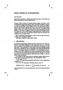
Fig. 7a–c The soil map for the SRS, which contains 31 mappable soil series for the Savannah River Site, was furnished to the project in an ARC/INFO coverage based on Rogers (1990). In this coverage, soils are classified according to their hydrologic group and percent organic matter. a Hydrologic soil groups are based on their run-off-producing characteristics and were assigned to five groups, with soil groups ranging from (A) soils with a high infiltration rate and a low run-off potential to (D) soils with a very slow infiltration rate and a high run-off potential, and finally urban. b Soils are grouped into four organic matter classes: low, less than 2%, low to moderate, 2–3%, moderate to very high, greater than 3%, and urban. c The composite soil map for this study consists of soils classified according to hydrologic group and percent organic matter as shown in Table 4
sensitivity of areas with three-dimensional variations in geological sequences and rates of soil infiltration. Colors for the combined categories on the matrix (and for the eventual map) were assigned such that ’credit’ was given for the ability of a soil to provide additional protection to aquifers and to decrease the likelihood of a contaminant reaching the top of the Ellenton. From high sensitivity to low sensitivity, matrix and map colors were assigned as purple, dark red, orange, peach, yellow, yellowish-brown, brown, light blue, blue, light green, dark green. The scheme for deciding which colors should be placed in the appropriate matrix boxes and the degree of ’credit’ given for the soil factor is only relative and does not reflect any quantitative or significant difference from color to color. Soil factor credit may vary depending on the user or on a specific contaminant of concern. For example, the fate of organic materials introduced at land surface could be significantly affected by soil organic matter and degree of infiltration. However, nonorganic chemicals and radionuclides buried beneath the surface would be unaffected by the soil. A generalized contamination potential map was then generated from the matrix (Fig. 9). Colors show the transition from high to low aquifer sensitivity. More importantly, the map shows the significance of the soil factor for either decreasing or increasing contamination potential. For example, the highest contamination potential rating based only on the stack-unit sequences for the GSA study area is where the Congaree is exposed at the surface along Upper Three Runs Creek. However, this re274
Environmental Geology 35 (4) September 1998 7 Q Springer-Verlag
gion has soils of high organic matter (peat) and very slow infiltration, suggesting a local discharge region. Therefore, inclusion of soils information modifies and thereby lowers the contamination potential rating in this region. The presence of urban land also reduces the contamination potential rating. In Fig. 5, urban land was treated as having a similar effect on recharge as Hydrologic Group D soils with very high organic matter. The highest contamination potential ratings in the study area primarily occur on the sides of valley of Upper Three Runs Creek and its tributaries. Here, the Tan Clay and Upland interval have been eroded and soils lack organic matter and have high infiltration rates. Areas of moderate contamination potential occupy much of the area between Upper Three Runs Creek and Four Mile Creek. Even though this upland area is characterized by low organic matter soils with high infiltration rates, in the subsurface, thin Tan Clay and Green Clay aquitards provide some degree of protection. Two areas between Upper Three Runs Creek and Four Mile Creek ranked with a low contamination potential rating are not only characterized by thick Tan Clay and the presence of Green Clay and Upland deposits, but also have an “urban” soil classification (e.g., parking lots, buildings, and other structures). The lowest contamination potential ratings in the study area primarily occur in the area of Four Mile Creek where soil organic matter is generally high and infiltration is low, Tan Clay is thick, and the Green Clay and the Upland interval are both present but may be thin.
Cyan/Blau
Cases and solutions
Fig. 8 Generalized geologic stack-unit map is derived from the 79-unit geologic stack-unit map but simplified to 12 units. As shown in the correlation chart of 79 stack units to 12 generalized stack units, the simplification is based on the thickness and absence/presence of three hydrogeologic units within the GSA judged to have the most direct influence on preventing or promoting vertical contaminant transport. These units are the Tan Clay, Green Clay, and Upland interval. See Table 1 for definition of letter codes
Hydrogeologic/hydrologic component of the contamination potential map of the GSA In addition to the three-dimensional distribution of geologic materials and soils, the potential for any geologic unit to become contaminated is also dependent upon the three-dimensional, up-gradient pathways of the groundwater that enters it. Therefore, the position of the various geologic units in the groundwater-flow regime can be important in differentiating the contamination potential from location to location. Areas where the hydraulic gradient is strongly upward would, all other factors being equal, have a lower contamination potential than areas where the hydraulic gradient is strongly downward. Areas where the vertical gradient is weak or fluctuates between upward and downward would presumably have an intermediate contamination potential. For the GSA study area, the hydraulic head differences between the water table and the Barnwell-McBean, and
the Barnwell-McBean and Congaree, respectively, are the significant groundwater flow components for the contamination potential analysis. Unfortunately, the hydraulichead data above the Tan Clay (which is a surrogate for the water table) are insufficient to contour a head difference map between the water table and the BarnwellMcBean. The hydraulic-head difference between the Barnwell-McBean and the Congaree was estimated by subtracting the potentiometric surface of the Congaree from the potentiometric surface of the Barnwell-McBean derived from mean water-level measurements in monitoring wells screened exclusively in the respective units. Positive values show a vertically downward hydraulic gradient. The large difference in heads between the two units is, in part, due to the significance of the Green Clay as a confining unit throughout the GSA study area. The hydrogeologic/hydrologic factors that may contribute to the contamination potential of the GSA study area,
Environmental Geology 35 (4) September 1998 7 Q Springer-Verlag Black/Schwarz Yellow/Gelb Magenta/Rot Cyan/Blau
X
275
Cyan/Blau
Cases and solutions
troduced at land surface to move downward through five units to the top of the Ellenton. However, the mapping program was designed to accommodate additional data or reinterpretations of existing data at any time. Therefore, the model could easily be adapted to account for a contaminant introduced at land surface to move downward to any position within the units comprising the upper groundwater flow system. This methodological approach and the resulting analyses are vital for site planners in order (1) to evaluate geologic conditions and potential or actual contamination problems; or (2) to evaluate groundwater monitoring networks. Some specific tasks this methodology can greatly benefit are: (1) the selection of areas that have relatively low contamination potential for locating future facilities; (2) the screening of potential ’hot spots’; and (3) designing or the enhancing while relevant, do not exhibit sufficient spatial variation of groundwater monitoring programs. to warrant incorporation into the contamination potenThe integration of soils information with the geologic tial index for the GSA. As the contamination potential stack-unit map provides additional detailed information analysis expands to a site-wide spatial scale, these factors to discriminate further areas of varying sensitivities at will presumably become spatially differentiable and there- the GSA. Sensitivity ratings based only on the geologic fore incorporated into the contamination potential index stack-unit information were lowered to account for areas of the larger area. of high organic content and slow infiltration rates (often these areas are in groundwater discharge zones). The sensitivity map which incorporates soils and stack-unit data is particularly useful for evaluating potentially adverse Summary and conclusions events or land-use activities occurring at land surface such as accidental spills, applications of chemicals and An evaluation of groundwater contamination potential fertilizers, and nonburied waste disposal. The sensitivity based on a stack-unit geological mapping approach was map developed from just the stack-unit geologic informasuccessful in effectively discriminating between areas of tion is best suited for evaluating potential contamination high and low sensitivities within the GSA at the SRS. The from buried and injected wastes, as well as any wastes model only evaluates the potential for a contaminant in- detected below ground surface. Fig. 9 A contamination potential map based on generalized geologic stack-unit map and composite soil map. A color scheme for the combined soil and generalized stack-unit map was created using a 12!8 square matrix integrating the 12 stack-unit sequence groups shown on the vertical axis with the eight soil organic-matter/hydrologic groups shown on the horizontal axis. Colors for the combined categories on the matrix (and for the eventual map) were assigned so that “credit” was given for the ability of a soil to provide additional protection to aquifers and to decrease the likelihood of a contaminant reaching the top of the Ellenton. The scheme for deciding which colors should be placed in the appropriate matrix boxes and the degree of “credit” given for the soil factor are only relative and do not reflect any quantitative and significant difference from color to color
276
Environmental Geology 35 (4) September 1998 7 Q Springer-Verlag Black/Schwarz Yellow/Gelb Magenta/Rot Cyan/Blau
X
Cases and solutions
Environmental Systems Research Institute (ESRI) (1993) Understanding GIS – the ARC/INFO method. Wiley, New York Fallaw WC, Price V (1995) Stratigraphy of the Savannah River Site and vicinity. Southeast Geol 35 : 21–58 Fleming AH (1994) The hydrogeology of Allen County, Indiana: a geologic and ground-water atlas. Indiana Geological Survey Special Report 57 Hoyer BE, Hallberg GR (1991) Groundwater vulnerability regions of Iowa. Iowa Geological Survey Bureau Special Map Series II, scale 1 : 500,000 Hutchinson MF (1988) Calculation of hydrologically sound digitally sound digital elevation models. 3rd Int Symp Spatial Data Handling, Sydney. International Geographical Union, Columbus, Ohio Keefer DA (1995) Potential for agricultural chemical contamination of aquifers in Illinois. Illinois State Geological Survey Environmental Geology 148 Keefer DA, Berg RC (1990) Potential for aquifer recharge in Illinois. Illinois State Geological Survey Map, scale 1 : 1,000,000 Lusch DP, Rader, CP Barrett LR, Rader NK (1992) Aquifer vulnerability to surface contamination in Michigan. Center for Remote Sensing and Department of Geography, Michigan Acknowledgements This project was funded through South CaState University, E. Lansing, MI rolina Universities Research and Education Foundation (SCURNystrom PG Jr, Willoughby RH, Kite LE (1986) CretaceousEF) Task Order 161 by Westinghouse Savannah River Company. Tertiary stratigraphy on the upper edge of the coastal plain Completion of this phase of Task 161 is the direct result of cobetween North Augusta and Lexington, South Carolina. Caoperation between personnel at the Earth Sciences and Rerolina Geological Society Field Trip Guidebook, 11–12 Octosources Institute, University of South Carolina (ESRI-USC) and ber 1986. South Carolina Geological Survey the researchers at WSRC. Researchers at ESRI-USC include: ElzPassero RN, Cohen FJ, Dulaney SJ, McNamara J, Benton bieta Covington, Geographic Information Systems (GIS) techniSE (1989) Determining the vulnerability of glacial drift aquifcal manager; James Rine, principal investigator and stratigraer systems in Michigan. 34th Annual Midwest Groundwater pher, John Shafer, hydrologist; Jeffrey Trudnak, research assistConference, Program with abstracts, 18–20 October 1989. Kalant; and Richard Berg, stack-unit mapping consultant from the amazoo, MI Illinois State Geological Survey. SRS technical oversight staff reRine JM, Shafer JM, Covington ER, Berg RC (1996) Develsponsible for monitoring task progress and furnishing approved opment of a GIS contamination potential map for a portion data sets are John Reed, Chris Bennett, and James Bollinger of of the General Separations Area, Savannah River Site, South WSRC. The authors thank SCUREF and WSRC for permission Carolina. Earth Sciences and Resources Institute, University to publish a portion of the results from Task Order 161. of South Carolina, Report 96-10-F124 Rogers VA (1990) Soil survey of Savannah River Plant area, parts of Aiken, Barnwell, and Allendale counties, South Carolina. US Dept of Agriculture, Soil Conservation Service Schmidt RR (1987) Groundwater contamination susceptibility in Wisconsin. Wisconsin Department of Natural Resources. Wisconsin’s Groundwater Management Plan Report 5. PUBLAadland RK, Gelici JA, Thayer PA (1995) Hydrogeologic WR-177-87 framework of west-central South Carolina. State of South CaShafer JM (1985) An assessment of groundwater quality and rolina Department of Natural Resources, Water Resources hazardous substance for a statewide monitoring strategy (P.A. Division Report 5 83–1268). Illinois State Water Survey, Contract Report 367 Aller L, Bennett T, Lehr JH, Petty RJ, Hackett G (1987) Siple GE (1967) Geology and groundwater of the Savannah RivDRASTIC: a standardized system for evaluating groundwater er plant and vicinity, South Carolina. US Geol Surv Water pollution potential using hydrogeologic settings. US EnvironSupply Paper 1841 mental Protection Agency EPA/600/2–87/035 Soller DR (1992) Applying the DRASTIC model – a review of Berg RC (1994) Geologic aspects of a groundwater protection county scale maps. US Geol Surv Open-File Report 92–297 needs assessment for Woodstock, Illinois: a case study. IlliSoller DR, Berg RC (1992) A methodology for the regional nois State Geological Survey Environmental Geology 146 assessment of aquifer contamination potential based on geoBerg RC, Greenpool MR (1993) Stack-unit geologic mapping: logic framework. Environ Geol Water Sci 19 : 205–213 color-coded and computer-based methodology. Illinois State Trent VP (1992) Ground-water pollution susceptibility map of Geological Survey Circular 552 Georgia: GIS-1. Dept of Natural Resources Environmental Berg RC, Kempton JP (1988) Stack-unit mapping of geologic Protection Division, Georgia Geologic Survey, GIS Data Bases, materials in Illinois to a depth of 15 meters. Illinois State Atlanta, GA, 6.9 MB Geological Survey Circular 542 Berg RC, Kempton JP, Stecyk AN (1984) Geology for planU.S. Environmental Protection Agency (1993) Ground water rening in Boone and Winnebago Counties. Illinois State Geosource assessment. U.S. EPA Office of Ground Water and logical Survey Circular 531 Drinking Water, EPA 813-R-93-003, Washington DC
Most importantly, the methodological approach designed for the GSA provides a template for expansion of the mapping exercise to the entire 790-km 2 area of the SRS, as well as other applicable areas on the southeastern Coastal Plain. This study extended the depth to which stack-unit geological mapping can be applied to delineate subsurface distributions of materials. (The technique was previously successful to a depth of 30 m.) In addition, it proved that a technique developed in the Midwest to delineate glacial sediments is applicable in other geologic environments. The technique was successful because of the similarity, from a geologic materials perspective, of glacial and coastal plain sediments; both environments are characterized by unlithified sorted sediments and fine-grained deposits, both of which are relatively flat-lying. Research is currently underway in more complex geologic environments of the SRS to test further the limits of this methodology.
References
Environmental Geology 35 (4) September 1998 7 Q Springer-Verlag
277