NASA Johnson Space Center, Houston, Texas 77058 ... The primary debris sources during ascent of the Space Shuttle are the insulating foam covering the ...
Development and Verification of a Probabilistic Model for Space Shuttle Debris Transport Ben H. Thacker*, David S. Riha.†, Jason B. Pleming‡, and Luc J. Huyse§ Southwest Research Institute, 6220 Culebra Road, San Antonio, Texas 78238-5166 and Reynaldo J. Gomez** and Phillip C. Stuart†† NASA Johnson Space Center, Houston, Texas 77058 As a result of the conclusion that debris impact caused the damage to the left wing of the Columbia Space Shuttle Launch Vehicle (SSLV) during ascent, the Columbia Accident Investigation Board (CAIB) recommended that an assessment be performed of the complete debris environment experienced by SSLV during ascent. Eliminating the possibility of debris transport is not possible; therefore, a flight rationale based on probabilistic assessment is required for the SSLV return-to-flight (RTF). The assessment entails identifying all potential debris sources, their probable geometric and aerodynamic characteristics, and their potential for inflicting damage to the SSLV. This paper describes the development and verification of a probabilistic debris transport analysis (DTA) procedure.
I.
Introduction
The primary debris sources during ascent of the Space Shuttle are the insulating foam covering the external tank (ET) and the ice that can form on the ET before and during launch. Upon detachment, aerodynamic drag forces act to slow the speed of the debris, thereby increasing the relative velocity between the debris and the orbiter. Also during transport, lift forces act to disperse the debris about their idealized trajectories. Therefore, the farther downstream the debris travels before impact, the greater the potential impact kinetic energy and crossrange (dispersion). There are multitudes of uncertainties in the modeling of debris transport. Experimental evidence indicates that a range of debris shapes, typically thin and roughly conical, can be shed from the ET acreage foam. In the debris transport analysis, drag models are used to predict the stochastic trajectory of the debris (zero-lift line) and impact velocity. The crossrange scatter, characterized from experimental data, determines where the debris could potentially impact the SSLV. In addition to the debris transport uncertainties, trajectory calculations have also been shown to be highly nonlinear and highly sensitive to initial conditions. An accurate simulation-based analysis methodology is needed that can predict with high confidence the probability of impact and damage to SSLV thermal protection system (TPS) components due to debris impact. This need can be met by developing a probabilistic methodology that takes full account of the stochastic nature of the
*
Director, Materials Engineering, 6200 Culebra Road, San Antonio, Texas, Associate Fellow. Principal Engineer, Materials Engineering, 6200 Culebra Road, San Antonio, Texas, Member. ‡ Research Engineer, Materials Engineering, 6200 Culebra Road, San Antonio, Texas, Member. § Principal Engineer, Materials Engineering, 6200 Culebra Road, San Antonio, Texas, Member. ** Technical Manager, 1601 NASA Parkway, Houston, Texas, Senior Member. †† Aerospace Engineer, 1601 NASA Parkway, Houston, Texas. †
1 American Institute of Aeronautics and Astronautics
debris size, shape and pop-off velocity; drag and crossrange models and model parameters; and impact damage to TPS components. Southwest Research Institute (SwRI®) was tasked to assess the NASA-JSC probabilistic debris transport analysis (DTA) methodology in support of the STS-114 mission. The approach taken was to develop a probabilistic DTA capability based on the JSC DTA tools integrated with the SwRI-developed NESSUS® probabilistic analysis software. This new model will be referred to herein as the NESSUS-JSC DTA model. This approach provides JSC with: 1) a verification of the JSC DTA model simulations, 2) a powerful probabilistic analysis framework based on JSC DTA tools, and 3) a more user-friendly and flexible probabilistic DTA simulation environment that will reduce the chance for error and time required to perform “what-if” studies.
II.
Conceptual Model
The debris release, transport, and damage to the Space Shuttle TPS due to impact during ascent can be divided into a series of conditional events: •
E1: debris is released
•
E2: debris impacts the TPS
•
E3: debris impact causes damage
Failure occurs when these three events occur concurrently. Mathematically this can be expressed as the intersection of the three events:
Pr( failure) = Pr( E1 ∩ E2 ∩ E3 ) = Pr( E1 ) Pr( E2 | E1 ) Pr( E3 | E1 ∩ E2 )
(1)
In Equation 1, “ ∩ ” denotes the intersection of events, Pr( E1 ) is the probability that debris is released,
Pr( E2 | E1 ) is the probability of impact given a release has occurred, and Pr( E3 | E1 ∩ E2 ) is the probability of failure (damage) given that release and impact have both occurred. These three probabilities will be referred to herein as the basic “elements” of the failure event. Each element in Equation 1 corresponds to different modeling disciplines, i.e., debris release, debris transport and impact, and TPS damage. Numerical models that are used to predict release, transport and damage will typically account for the conditional nature of the event. For example, a computational fluid dynamics (CFD) based transport model implicitly considers the conditional event E2|E1. However, the numerical models comprising the three elements in Equation 1 will generally be correlated due to common random variables; therefore, a systems model will generally be required to assess the total probability of failure. A. Debris Release (Event E1) Debris release, or “pop-off,” can be characterized by two phenomena: •
Frequency of divot pop-off (Occurrence)
•
Size of the divot (Intensity)
The occurrence model describes how frequently divots pop off. When the probability of a pop-off at a given location is not affected by pop-offs that occur elsewhere (in space or in time), the pop-off occurrence is adequately described by a Poisson process. If pop-off behavior does depend on the current state, a more sophisticated occurrence model, such as a Markov chain, can be used. A Poisson process is characterized by an occurrence rate λ. The use of a “rate” implies that the resulting probabilities will be associated with a given time period (e.g., pop-off rate per launch, pop-off rate per year, etc.). This flexibility allows the model to be used to evaluate failure probability for one mission, or many missions.
2 American Institute of Aeronautics and Astronautics
The occurrence rate, λ, may be modeled as a deterministic constant or as a function of other variables. For example, λ could be given as a function of Mach number to account for the known dependence on surface pressure. Also, if the pop-off rate depended on the local temperature and material properties, a deterministic rate that is conditional on the temperature and material properties could be used. Whether the occurrence rate is represented as a constant or as a function of other variables, variability in the popoff rate can be modeled using a random variable. For example, a Gamma distribution (the Poisson’s conjugate prior) could be used to represent the uncertainty in the mean pop-off rate. When modeled using a Gamma distribution, the pop-off rate itself is considered either to be uncertain or to fluctuate as a function of other variables. Because the pop-off event is spatially inhomogeneous, the model will be location dependent. Accounting for the location dependence in the pop-off rate will depend on the approach that is used to model damage to the TPS. If damage to the TPS is cumulative, then an integrated approach will be required to accumulate damage due to repeated impacts on the various TPS elements (RCC panels and tiles). If damage to the TPS is not cumulative, then the location dependence of the pop-off rate can be eliminated by using the maximum expected debris size taken from a debris size distribution. The debris size distribution (intensity model) can be constructed from an analysis of launch video. The sizes of the divots captured on video can be measured and used to construct an empirical or parametric PDF. Alternatively, the debris size distribution could be computed from a first-principle physics model of the debris undergoing ascent loading (dynamic pressure and vibratory). Divot size is a function of void/flaw size, depth and material toughness. The CDF of the debris size distribution is denoted as FD(d0). If only the maximum expected divot size is considered (effectively assuming that damage to the TPS is not cumulative), the unconditional probability that the maximum size divot released during a single launch is less than d can be computed by integrating the Poisson occurrence model over the range of possible occurrence rates:
Pr( x ≤ d 0 ) = F (d 0 ) = ∫ exp {−λ t [1 − FD (d 0 )]} f Λ (λ )d λ
(2)
Pr( x ≤ d 0 ) = F (d 0 ) = exp {−λt [1 − FD (d0 ) ]}
(3)
where fΛ(λ) is a Gamma probability distribution representing a variable occurrence rate, λ is the occurrence rate per unit time, and t is the number of time periods. The occurrence rate, λ, and time, t, are related. For example, when λ is expressed per launch, then t is the number of launches over which period the risk is considered. If it is assumed that the TPS will be replaced after each flight, then t would be equal to 1. If λ is expressed on a per minute basis, then t would be the length of the launch in minutes. By making λ a function of time, one can account for varying pop-off rates during various stages of the launch. When the occurrence rate is assumed to be constant, Equation 2 simplifies to:
An approach for treating the location dependence of pop-off rate and/or size-distribution is to compute the debris release distribution on a per panel or location basis. For example, if the location (acreage panel, intertank flange, etc.) is represented by, iET, Equation 2 becomes:
Pr( x ≤ d 0 | iET ) = F (d 0 ) = ∫ exp {−λ (iET )t [1 − FD (d 0 | iET ) ]} f Λ (λ , iET )d λ
(4)
which then requires the conditional size and occurrence rate distributions to be developed as functions of the respective locations on the external tank. B. Debris Transport and Impact (Event E2|E1) This is a conditional model and breaks down into two parts: •
Prediction of kinetic energy at impact (Intensity)
•
Probability of impact (Occurrence)
A debris transport model, based on a CFD flowfield, computes the trajectory of a particle and the relative velocity of a debris divot with respect to the Shuttle based on the continued acceleration of the Shuttle and the
3 American Institute of Aeronautics and Astronautics
slowdown of the divot due to aerodynamic drag. The final velocity of the divot primarily depends on the length of the debris travel path and the aerodynamic drag model. Uncertainties in the basic CFD and drag model variables yield uncertainties in the computed trajectory and divot velocity. In addition, the travel path of the debris off of the freestream trajectory will contain additional uncertainty due to the random lift forces that act on the debris. The aerodynamic lift is represented in a crossrange model. If the uncertainty in lift is assumed to be rotationally symmetric about the (uncertain) freestream trajectory, then the crossrange can be modeled by a spatial Gaussian distribution (crossrange cone). Otherwise, the crossrange distribution must be constructed from experimental data to reflect properly the directional dependence. An additional consideration arises due to the swept nature of the Shuttle wing: because of the angle at which the wing is swept back, the divot path length (and hence the impact velocity) will depend on the location of the divot within the crossrange cone. Because the crossrange cone created by the random aerodynamic lift forces acting on the debris divot will generally be larger in area than the intersecting area of the TPS, the divot has some chance of not impacting the TPS. Therefore, the probability of impact must be computed as the integral of the crossrange distribution over the portion of the cone that actually intersects with the wing TPS. C. TPS Damage (Event E3|E2∩E1) Damage to the various TPS elements depends on the occurrence of the release and impact events. The damage event itself can be divided into two parts: •
Impact conditions (Occurrence)
•
Damage to the TPS (Intensity)
The energy transfer, and hence damage to the TPS, will depend on the impact conditions. Besides velocity, the two primary impact conditions are the angle of impact between the divot trajectory and the TPS element, and the location of impact on the TPS. If a first-principle (finite element) simulation of the impact event is used, the angle and location of impact can easily be considered in the analysis because they both constitute basic inputs to the calculation. If a simplified impact model is used that does not consider impact conditions explicitly, then two approaches could be taken: 1) Worst-case conditions can be assumed, or 2) engineering relationships can be developed and used that relate the distribution of energy imparted to the TPS given the location and angle of impact. Worst-case conditions—namely straight on impact at the weakest location on the TPS—are probably highly unlikely and, consequently, will lead to overly conservative results. In general, the probability of damage to a TPS element can be computed given an impact by divot of mass, m, traveling at speed, v, and impacting location y. In the simplest form, tolerance to damage can be taken as a deterministic threshold using some metric, such as kinetic energy or momentum. Impacts yielding damage beyond threshold are considered failures. Higher fidelity models of damage could consider 1) the variability in the damage threshold, 2) first principle probabilistic behavior of the TPS subject to debris impact, 3) cumulative damage to the TPS due to multiple impacts, 4) effects of repair and/or replacement of the TPS between missions, or 5) any combination of the above. The TPS damage event can be evaluated by evaluating the limit-state function:
g =C−E
(5)
where C is the capacity of the TPS to withstand impacts and E is the environment (impact load) induced by the impacting debris. The probability of failure is then given by the condition
p f = Pr [ g ≤ 0]
4 American Institute of Aeronautics and Astronautics
(6)
The failure probability can be assessed by plotting pf for the various sections of the TPS, by location of debris popoffs, or a combination of the two. If the TPS capacity is not affected by previous impacts, then cumulative damage need not be considered. This results in a straightforward pass-fail criterion based on the maximum expected divot size (for all time and locations). The limit-state function is then time-independent (the time dependency is effectively removed by specifying the return period n) and a failure occurs when g(x) < 0. The environment is given by the maximum impact during the time period considered. If cumulative damage to the TPS is deemed important, then the likelihood of multiple or neighboring impacts should first be considered. Although the material may accumulate damage prior to failure, explicit modeling of this process may not be warranted based on the small possibility of repeated impacts. This probability can be assessed by computing the probability of multiple impacts for various regions of the TPS. Another calculation is needed to assess the consequence of repeated impacts to the TPS. If the probability of multiple impacts is sufficiently small, and the consequence of multiple impacts is acceptable, cumulative damage effects to the TPS can be ignored. If cumulative damage to the TPS cannot be ignored, then explicit (finite element) modeling of the impact event should be included in the damage event probability calculation. Alternatively, or possibly in conjunction with a finite element impact simulation, various probabilistic modeling approaches could be used to represent the stochastic nature of the damage process. For example, a Markov chain model could be used to represent the probability of reaching more severe damage levels based on the current damage level (but not earlier damage levels).
III.
NESSUS-JSC Debris Transport Analysis Model
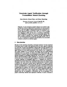
A. Overview The debris transport analysis (DTA) model is based on the NESSUS probabilistic analysis software [1]. NESSUS (Numerical Evaluation of Stochastic Structures Under Stress) is a general-purpose tool for computing the probabilistic response or reliability of engineered systems. NESSUS can be used to simulate uncertainties in loads, geometry, material behavior, and other user-defined random variables to predict the probabilistic response, reliability and probabilistic sensitivity measures of engineered systems. The software was originally developed by a team led by SwRI as part of the NASA project entitled Probabilistic Structural Analysis Methods (PSAM) for Select Space Propulsion Components [2]. NESSUS allows the user to perform probabilistic analysis with analytical models, external computer programs such as commercial finite element codes, and general combinations of the two. The NESSUS graphical user interface (GUI) is highly configurable and allows tailoring to specific applications. This GUI provides a capability for commercial or in-house developed codes to be easily integrated into the NESSUS framework. Eleven probabilistic algorithms are available in NESSUS including Monte Carlo simulation, first order reliability method, advanced mean value method and adaptive importance sampling [3]. NESSUS provides most well-known probability distributions as well as correlations between the random variables. These probabilistic modeling capabilities allow refinement of the analyses as probabilistic distribution information becomes available. In addition, from the NESSUS problem statement window, it is possible to specify an area of interest (i.e. RCC panel number) and a desired Mach number. Additional random variables can easily be added. This model provides a framework for rapid parameter changes and what-if analyses. Figure 1 shows the NESSUS problem statement window with all of the model input variables. The model is currently set up to retrieve kinetic energy values, but the framework can be easily modified to retrieve and/or process any quantity of interest.
5 American Institute of Aeronautics and Astronautics
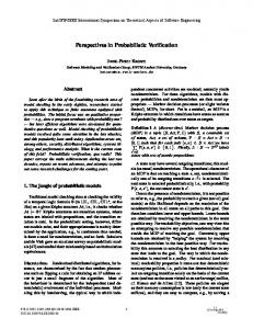
Figure 1. NESSUS problem window showing the NESSUS-JSC DTA model. B. Verification with NASA-JSC DTA Model The goal of the verification simulation is to compare outputs from the NESSUS-JSC DTA model at each impact location from two release locations with the JSC “butterfly plots” [4]. Two analyses were performed at each of the four Mach numbers of interest (2.50, 2.75, 3.00, and 3.50). The purpose of the first analysis was to develop the constant mass line data for the selected release locations (the LO2 PAL ramp and the LO2 intertank flange), shown in Figure 2. A Monte Carlo analysis using 5,000 samples was performed for each Mach number. All model inputs were held at their mean values except for the pop-off velocity magnitude (vel_mag) variable, which was assumed random as given by the JSC-supplied inputs. For each sample generated by NESSUS, the DTA model was executed and the resulting data sorted by RCC panel number. Next, the recorded KE values were sorted by maximum KE for each panel. At the completion of the simulation, the results were post-processed. The results are indicated on the butterfly plots in Figures 3-4 for the two release locations. These results are shown as the lower bound of the “SwRI” results.
6 American Institute of Aeronautics and Astronautics
3, 6. PAL ramps (BX250/265/ PDL)
4. Bipod Closeout (BX265 / PDL)
2. LO2 Tank intertank flange (BX250)
7. LH2 Tank Acreage (NCFI 24-124)
5. LH2 Tank intertank flange (BX 265)
11.
Intertank Acreage (NCFI 24-124)
8,9,10. LO2 / Intertank /LH2 Ice/Frost ramps (SLA 561/ PDL)
Figure 2. End-to-end foam on RCC cases.
2000
RCC Fail FoS = 1.0
RCC Fail FoS = 1.0
RCC Fail FoS = 1.7
RCC Fail FoS = 1.7
Kinetic Energy (ft-lb)
1500
1000
NASA-JSC SwRI
500
0 -23
-21
-19
-17
-15
-13
-11
-9
Port RCC Panel #
-7
-5
-3
-1
1
3
5
7
9
11
13
15
Starboard RCC Panel #
Figure 3. LO2 PAL ramp butterfly plot.
7 American Institute of Aeronautics and Astronautics
17
19
21
23
2000 RCC Fail FoS = 1.0
RCC Fail FoS = 1.0
Kinetic Energy (ft-lb)
1500
RCC Fail FoS = 1.7
SwRI
RCC Fail FoS = 1.7
1000 NASA-JSC
500
0 -23 -21 -19 -17 -15 -13 -11
-9
Port RCC Panel #
-7
-5
-3
-1
1
3
5
7
9
11
13
15
17
19
21
23
Starboard RCC Panel #
Figure 4. LO2 intertank flange butterfly plot. The second analysis considered additional random variables and will be referred to as the “3σ analysis.” The purpose of the 3σ analysis was to verify the upper limit on the NASA-JSC results shown in Figures 3-4‡‡. NASA developed this data by using their own uncertainty code. To independently verify their results, a Monte Carlo analysis with 5000 samples was performed using the five random variables in Table 1. Model Input ACCX ACCY ACCZ MET vel_mag cdscale rhoscale uscale rho_debr
Table 1. NESSUS-JSC DTA Model Inputs. Distribution Type Description Deterministic Vehicle acceleration vector, X-dir (ft/sec) Deterministic Vehicle acceleration vector, Y-dir (ft/sec) Deterministic Vehicle acceleration vector, Z-dir (ft/sec) Deterministic Mission Elapsed Time (Seconds) Uniform Pop-off Velocity magnitude (ft/sec) Uniform Debris drag coefficient (Nominal) Normal Freestream density, (Nominal) Normal Freestream Velocity (Nominal) Normal Foam density, (lbm/ft^3)
Tables 2-3 list the deterministic and probabilistic data for the variables at each of the different Mach numbers. The data in Table 2 was obtained from STS missions 111 and 113.
MACH 2.50 2.75 3.00 3.50 ‡‡
Table 2. Deterministic inputs for each Mach number. ACCX ACCY ACCZ 76.414 0.050 2.708 76.795 0.097 2.899 77.447 0.123 3.150 76.925 0.139 3.670
These results are labeled “Debris mass (lbm) – Max Void + 3σ uncertainty” data in Ref. [4]. 8 American Institute of Aeronautics and Astronautics
MET 81.559 84.632 91.658 102.018
Mach 2.50 2.75 3.00 3.50
Table 3. Probabilistic inputs for each Mach number. Vel_mag Cdscale rhoscale Uscale Mean Std. Mean Std. Mean Std. Mean Std. 111.942 17.321 1.000 0.311 1.000 0.065 1.000 0.003 111.942 17.321 1.000 0.311 1.000 0.075 1.000 0.034 111.942 17.321 1.000 0.311 1.000 0.088 1.000 0.040 111.942 17.321 1.000 0.311 1.000 0.121 1.000 0.004
rho_debr Mean Std. 2.340 0.253 2.340 0.253 2.340 0.253 2.340 0.253
As shown in Figures 3-4, the NESSUS-JSC DTA results compare well to JSC butterfly plot results. There was some difference in the three-sigma uncertainty results for both release locations, but it was very small. For example, the LO2 PAL ramp release location was approximately 3% different and the LO2 intertank flange release location was approximately 5% different. Some possible reasons for these differences are: • • •
SwRI considered the pop-off velocity magnitude (vel_mag) to be random, whereas the JSC calculations considered vel_mag to be deterministic. (Probabilistic sensitivities, presented later in this report, show vel_mag to be unimportant.) SwRI investigated four Mach numbers (2.50, 2.75, 3.00, and 3.50), whereas JSC considered Mach numbers 2.75 and 3.00. SwRI used the debris transport suite of codes to compute the upper bound results from the 3σ analysis, whereas the JSC analysis used the program “dunc,” which assumes a 1D approximation to the flow field.
C. Preliminary Probabilistic Analysis Given the satisfactory verification described in the previous section, a preliminary probabilistic analysis using the NESSUS-JSC DTA model was performed. Two release locations were analyzed: LO2 PAL ramp and LO2 intertank flange. For each release location, two limit capacity levels were assumed: the upper capacity value corresponds to a safety factor 1.0, and the lower capacity value corresponds to a safety factor of 1.7. The debris proximity code (dprox) code computes all possible panels that a single piece of debris could hit, but it does not indicate the relative likelihood of hitting a specific panel. Figure 5 shows the effect of the release location on the probability of debris impact for each of the 22 RCC panels on the starboard side of the Shuttle with the assumption that the debris is equally likely to hit any of the panels identified by dprox. In this assumption, each piece of debris impacts only once and the sum of all panel probabilities (the area under the curve in Figure 5) gives the total probability of a piece of debris impacting the Shuttle panels. For the PAL ramp release location this probability is 99.7%, and for the Intertank flange location, this probability is 30%. The kinetic energy (KE) at impact was computed by the debris code from the debris velocity and mass. A total of 20,000 simulations were run: 5,000 at each of the four Mach numbers of interest (2.5, 2.75, 3.0 and 3.5). Figure 6 shows the conditional probability of damage, where damage is defined as the kinetic energy exceeding the panel capacity with a factor of safety (FoS) of either 1.7 or 1.0. The qualifier “conditional” is used to indicate that the results assume that a divot has been released and that impact has occurred. The results shown in Figure 7 account for the probability of impact by multiplying the probabilities given in Figures 5 and 6 for each RCC panel. It should be noted that the probabilities shown in Figure 7 are still conditional on divot release, i.e., probability of release is assumed equal to 1.0.
9 American Institute of Aeronautics and Astronautics
0.06 LO2 pal ramp
Probability of Impact
0.05
0.04
0.03
0.02
LO2 intertank flange
0.01
0.00 5
10
15
20
Starboard Panel Figure 5. Probability of debris impact as a function of release location. 1e-1
LO2 intertank flange, FoS = 1.7
Probability of Damage Given Impact
1e-2 1e-3 1e-4 1e-5 1e-6 1e-7
LO2 pal ramp, FoS = 1.7
1e-8 1e-9 1e-10 1e-11
LO2 intertank flange, FoS = 1.0
1e-12 1e-13 1e-14 5
10
15
20
Starboard Panel Figure 6. Conditional probability that the kinetic energy exceeds the panel capacity (damage). These results assume that a divot was released and impacted a panel.
10 American Institute of Aeronautics and Astronautics
1e-3
LO2 intertank flange, FoS = 1.7
1e-4
Probability of Damage
1e-5 1e-6 1e-7 1e-8 LO2 pal ramp, FoS = 1.7
1e-9 1e-10 1e-11 1e-12
LO2 intertank flange, FoS = 1.0
1e-13 1e-14 5
10
15
20
Starboard Panel Figure 7. Probability of damage given that a divot was released. This figure is obtained by multiplying the probabilities given in Figures 5 and 6. A summary of the probability of damage (kinetic energy exceeds the RCC panel capacity) is given in Table 4. In these results, it is assumed that a divot can impact only a single panel. Consequently, the total probability of failure in any of the 22 panels on the starboard side is computed as the sum over all panels. For the two release locations considered, the maximum KE is achieved for the intertank flange location (FoS=1.7) and is slightly greater than 0.28% (see Table 4). If symmetry were assumed, the risk to the entire Shuttle would be approximately 0.57%. It should be noted that the probabilities given in Table 4 are based on several assumptions (use of dprox and debris codes, uniform distribution of panel impact location, uncertainty quantification of the random variables, absence of release rate model, etc.).
11 American Institute of Aeronautics and Astronautics
Table 4: Probability that kinetic energy at impact exceeds the RCC panel capacity. Values are given for all panels and for factors of safety 1.0 and 1.7. Failure probabilities less than 10-15 are not listed. The values account for the probability of impact but are conditional upon the release of a divot. Panel # intertank flange PAL ramp FoS 1.0 FoS 1.7 FoS 1.0 FoS 1.7 1 -2 -3 -4 -5 -4.10E-08 6 -3.97E-08 7 -4.72E-08 8 7.31E-15 3.62E-04 1.19E-07 9 6.27E-15 3.82E-04 1.37E-07 10 3.74E-14 5.67E-04 5.17E-07 11 3.85E-14 5.97E-04 5.78E-07 12 4.29E-14 6.39E-04 6.60E-07 13 8.38E-05 3.70E-10 14 9.13E-05 4.08E-10 15 9.90E-05 4.32E-10 16 3.22E-06 1.72E-15 17 3.85E-06 1.35E-15 18 5.41E-06 1.61E-15 19 7.02E-06 2.55E-14 20 21 22 1.32E-13 2.84E-03 < 1.00E-14 2.01E-06 Total
IV.
Preliminary Probabilistic Sensitivity Analysis
Probabilistic sensitivity factors identify how much the failure (damage) probability changes if the parameters in the distribution (e.g., mean and standard deviation) change. They can be used to guide design changes to meet a target reliability, establish recommended limits on operating conditions, and direct the allocation of resources to manage the reliability. Figures 8 and 9 present probabilistic sensitivities for three scenarios in the debris transport analysis. In both figures, the left plot is the normalized derivative of the probability of damage with respect to the mean value of the random variable (Sμ) and the plot on the right is the normalized derivative of the probability of damage with respect to the standard deviation of the random variable (Sσ). The effect of Mach number at the LO2 intertank flange release location and the RCC panel 14 impact location is shown in Figure 8. As shown, the change in Mach number from 2.75 to 3.00 has little influence on the sensitivities. For this scenario, the pop off velocity (vel_mag) shows negligible importance, whereas the drag coefficient (cdscale) and flow field uncertainty are quite important. The small change in results between the two Mach numbers is likely the result of nearly equivalent probabilistic distributions for the flow field parameters (uscale, rhoscale) and the drag coefficient (cdscale).
12 American Institute of Aeronautics and Astronautics
1.0
0.5
LO2 Intertank Flange - Port RCC 14 - Mach 2.75
LO2 Intertank Flange - Port RCC 14 - Mach 2.75
0.5
0.0
0.0
-0.5
Sμ-0.5
Sσ-1.0
-1.0
-1.5
-1.5
-2.0
LO2 Intertank Flange - Port RCC 14 - Mach 3.00
LO2 Intertank Flange - Port RCC 14 - Mach 3.00
-2.0
-2.5 VEL_MAG RHOSCALE RHO_DEBR CDSCALE USCALE
VEL_MAG RHOSCALE RHO_DEBR CDSCALE USCALE
Figure 8. Probabilistic sensitivity factors at Mach 2.75 (light) and 3.0 (dark) for the LO2 intertank flange release location and the port RCC panel 14 impact location.
2.0
1.0
LO2 Pal Ramp - Starboard RCC 10 - Mach 3.00
LO2 Pal Ramp - Starboard RCC 10 - Mach 3.00
1.0
Sμ
0.0
0.0
Sσ
-1.0
-1.0
-2.0
-2.0
-3.0
-3.0
LO2 Intertank Flange - Port RCC 14 - Mach 3.00 VEL_MAG RHOSCALE RHO_DEBR CDSCALE USCALE
-4.0
LO2 Intertank Flange - Port RCC 14 - Mach 3.00 VEL_MAG RHOSCALE RHO_DEBR CDSCALE USCALE
Figure 9. Probabilistic sensitivity factors comparing two release and impact locations: LO2 intertank flange/RCC 14 (dark) and LO2 PAL ramp/RCC 10 (light). The effects of different release and impact locations (LO2 intertank flange/RCC 14 and LO2 PAL ramp/RCC 10) are shown in Figure 9. For the LO2 PAL ramp release location and RCC 10 impact location, the flow field uncertainty is more dominant with little influence from the drag coefficient. The uncertainty in the debris density, which governs the shape of the debris, is also more important for the PAL ramp release. The debris release from LO2 PAL ramp and impact on RCC 10 most likely will have a much shorter travel distance relative to the intertank flange release and RCC 14 impact. The shorter travel distance may be more influenced by debris shape (rho_debr) since it affects the cone of impact and the flow field properties while the drag coefficient has shorter time to influence the relative impact speed. Neither case shows importance for the pop off velocity and may be explained by the dominance of the flow field uncertainty.
13 American Institute of Aeronautics and Astronautics
While this demonstrative analysis is limited due to the many assumptions inherent in the current model, other uses of the probabilistic sensitivities include: 1. 2. 3.
Improve quantification of the flow field uncertainty (resource allocation) Pop off velocity is not important and can be removed from the analysis and modeling efforts (resource allocation) For evaluating launch debris, images should focus on debris shape/size and obtaining accurate Mach numbers and altitude when the release occurs. Pop off velocity does not appear important for these three scenarios (inspection planning).
V.
Summary and Conclusions
A probabilistic debris transport analysis (DTA) model was developed. Problem setup, definition and analyses were performed within the SwRI-developed NESSUS probabilistic analysis software. The DTA calculations were performed using a suite of (unaltered) codes and scripts provided to SwRI by NASA-JSC. The integrated model is referred to as the NESSUS-JSC DTA model. The NESSUS-JSC DTA simulation was successfully verified by comparing results to those from NASA-JSC. Results were also computed and presented from a preliminary probabilistic and sensitivity analysis based on the new NESSUS-JSC DTA model. The NESSUS-JSC DTA probabilistic tool provides a powerful and flexible framework within which debris transport assessment can be rapidly performed using various input assumptions, models or analysis scenarios. For example, the user can now easily substitute alternative physics models (e.g., foam or ice release), add or remove random variables, change or refine input probability distributions, and include input variable correlations. The framework also makes integrating new capabilities such as a first-principle debris release model or ice release models straightforward without time-consuming and error-prone software modifications.
VI.
Recommendations
The simulations presented contain no debris release information. Therefore, all results presented in this report are “conditioned” on the event of debris release. In other words, the results presented in this report represent an upper bound to the total probability because the probability of release is implicitly assumed to be equal to one. An additional analysis including mass as a random variable can be used to guide a decision on the required level of effort for developing a divot release model. A full release rate model is likely to be relatively complex and dependent on the mass (and size) of the divot as well as the release location, operating regime (Mach number), etc. It may require substantial effort to generate this information. Based on this additional analysis with mass included as a random variable, a conditional failure analysis will discern whether critical impacts are most likely associated with excessive velocity or with much larger than average divot mass. In the latter case a release rate model only needs to model large divot releases. Obviously several scenarios are possible but it is important to recognize that the probabilistic results of the current analysis can be used to guide the model-building effort for the next phase.
VII.
References
1
Southwest Research Institute, NESSUS User’s manual, www.nessus.swri.org, Version 8, 2004. Southwest Research Institute, “Probabilistic Structural Analysis Methods (PSAM) for Select Space Propulsion System Components,” Final Report, NASA Contract NAS3-24389, NASA Lewis Research Center, Cleveland, Ohio, 1995. 3 Southwest Research Institute, NESSUS Theory manual, Version 8, 2004. 4 NASA-JSC Debris Transport Analysis Peer Review, NASA Johnson Space Center, Houston, TX, 15 December 2005
2
14 American Institute of Aeronautics and Astronautics