remote control devices or manual controllers) are in use around the world in many ... operator to control one of the manipulators (the master arm) to generate ...
ASME Southeastern Region XI Technical Journal, Volume 3, April 2004; also presented at the ASME Southeastern Region XI Technical Conference, Mobile, Alabama, April 1-4, 2004.
DEVELOPMENT OF A FORCE-REFLECTING MANUAL CONTROLLER PROTOTYPE FOR TELEOPERATION Chandrasekar Reddy Puligari*, Mehmet Ismet Can Dede*, Sabri Tosunoglu*, and Daniel W. Repperger** *
Florida International University Department of Mechanical Engineering 10555 West Flagler Street Miami, Florida 33174
**
Air Force Research Laboratory Wright Patterson Air Force Base Dayton, Ohio 45433
ABSTRACT The robotics research program at Florida International University develops a broad range of robotic systems with a level of capability and robustness that supports long term, applied field operations. This paper provides insight into the design of a 1-Degree of Freedom (DOF) force-reflecting manual controller (FRMC) for the development of a teleoperation system by reviewing the wave variables technique, position/force control algorithms, platform design, servo systems, servo controllers and the related software developed. INTRODUCTION There are many tasks hazardous to human life which can be accomplished remotely using telerobotic manipulators. A telerobotic operation involves interaction between a human operator and a remote robotic system via communication channels. The performance of the communication channel plays an important role in the stability of the telerobotic system [1]. Passivity of the communication channel, having a constant delay, to guarantee the stability is first introduced by Anderson and Spong [2]. The technology has advanced to the stage where telerobots are versatile and effective enough to be used in a wide variety of circumstances. These teleoperators (also known as remote control devices or manual controllers) are in use around the world in many different environments as diverse as the nuclear reactors, police forces, military operations, space applications, and undersea tasks [3]. The system usually consists of two robot manipulators that are connected in such a way as to allow the human operator to control one of the manipulators (the master arm) to generate commands which map to the remote manipulator (the slave arm). A teleoperator system generally consists of a manual controller, control hardware and software, sensory feedback and a remote manipulator or device. Teleoperation tasks are distinguished by the continuous interaction between a human operator, teleoperator system, and the environment as illustrated in Fig. 1 [4].
Figure 1. Teleoperation system
A more recent development in the field of teleoperation is called telesensation. The term telesensation refers to the advanced teleoperator system that provides the operator with feedback. As a result, the operator is able to perceive the feel of presence at a remote site while he is in safe environment (workstation). The feel of presence can be provided by feedback information such as visual, aural, tactile and force feedback as represented in Fig. 2 [4].
Figure 2. Feedback components of a telesensation system
TIME DELAY PROBLEM While constant time delay problem for the communication channel is guaranteed with scattering formulation, which is also known as wave variables technique [2], another problem arises with the internet-
ASME Southeastern Region XI Technical Journal, Volume 3, April 2004; also presented at the ASME Southeastern Region XI Technical Conference, Mobile, Alabama, April 1-4, 2004. based communication, time-varying delays. In [5], a modified control that incorporates time-varying gains into the scattering transformation and feed-forward position control.
u s (t ) = f1 (t )u m (t − T (t )) v m (t ) = f 2 (t )v s (t − T (t ))
(3)
POSITION/FORCE CONTROL ALGORITHM STRUCTERS Figure 3. Scattering transformation for teleoperation with time delay
The transformation is given as follows by using the notation in [6]:
u m = 1 ( Fm + bx& m ) v m = 1 ( Fm − bx& m ) 2b 2b u s = 1 ( Fs + bx& sd ) 2b v s = 1 ( Fs − bx& sd ) (1) 2b where x& m and x& s are the respective velocities of the master and the slave. Fh is the force applied by the operator, and Fe is the force exerted on the slave by the environment. Fm is the force reflected back to the
Fs is the force information sent from the slave to master. x& sd is the
master from the slave robot.
velocity derived from the scattering transformation at the slave side. u and v denote the wave variables. In case of the constant communication delay where T is constant,
For the control scheme of the master and slave manipulators, more sophisticated controls than simple position or force controllers can be employed. This certainly would be one of the position/force control algorithms, which enables the controller to control both the position and the force applied to the environment simultaneously. As the interaction of the robot manipulator with its environment increases, there is a need to control both position of the manipulator and also force exerted by the manipulator to the environment. Two algorithms that briefly describe this position/force control of the manipulator, which are defined as Admittance Control and the Hybrid Position/Force Control are briefly presented below [7]. This work intends to implement both types of control algorithms on the FRMC. ADMITTANCE CONTROL Admittance control specifies a force set point and the set point is tracked by a force compensator, which attempts to comply with the environmental interaction and react quickly to the contact forces by rapidly modifying the reference motion trajectory [8]. The mechanical admittance is defined as
X& = AF
(4)
where the force compensator is defined in the s domain:
u s (t ) = u m (t − T ) v m (t ) = v s (t − T )
(2)
Fig. 4 shows the modified architecture of the wave variables technique for a time-varying communication delay.
X(s) = K(s) F(s) K(s) =
1 A(s) s
(5) (6)
where X is the position vector, X& is the velocity vector, and A represents the admittance term. Fig. 5 below illustrates the structure of a customary admittance control.
Figure 4. Time-varying gain
f i (t )
inserted in the communication
channel
As a result of this modified architecture, the new transmission equations come out to be
ASME Southeastern Region XI Technical Journal, Volume 3, April 2004; also presented at the ASME Southeastern Region XI Technical Conference, Mobile, Alabama, April 1-4, 2004. degrees of freedom. The matrix S determines the subspaces for which force or position are to be controlled, and s j is selected as either 1 or 0. When s j = 0, the j th DOF must be force controlled. S matrix can be constant, can change with configuration, or can continuously change in time [10]. The command torque is specified as Figure 5. Customary admittance control
τ =τp +τ
The command trajectory X C is defined as
X C = ∫ A( FD − F )dt
(7)
where FD represents the desired force trajectory, and
F is the force applied to the environment by the slave manipulator. Modeling the admittance as a secondorder system for this control scheme, it will then be defined as 2
A(s) = k d s + k p s + k i
(8)
which results in PID force compensator: K(s) =
k 1 . A(s) = k d s + k p + i s s
(9)
HYBRID POSITION/FORCE CONTROL The advantage of hybrid position/force control with respect to others is that the position and force information is analyzed independently to take advantage of the well-known control techniques for each component (position and force), and are combined only at the final stage when both have been converted into joint torques [9]. Fig. 6 shows the customary hybrid/force control scheme.
(10)
f
where τ p and τ
f
are the command torques acting in
position and force subspaces, respectively. In this way, position control and force control are decoupled. Normally, the position control law in Fig. 6 consists of a PD action and the force control law consists of a PI action. This is because a faster response is more desirable for position control and a small error is tolerable in force control. 1-DOF FORCE-REFLECTING MANUAL CONTROLLERS A force-reflecting manual controller (FRMC), or joystick, is one of the devices that can be used to control remote systems in teleoperation. A joystick is often a better control device than other available options such as a mouse, switchbox, keyboard or touchscreen input because the operator identifies better with the task [11]. However, to apply the concept of telesensation to a conventional teleoperation system, the joystick should be able to reflect forces experienced at the remote site. Such a system is known as a forcereflecting manual controller. While the input motion moves the remote system, forces experienced by the system are reflected to the manual controller so that the operator feels the forces acting on the system [12]. The architecture of force-reflecting manual controller mechanisms is classified either as serial or parallel structures. Either of these two architectures has certain advantages and disadvantages when applied to the telesensation systems. For instance, while the serial structure provides a larger workspace, parallel mechanisms tend to be more compact. The FRMC which is being developed at FIU is a parallel-structured force-reflecting manual controller. However, the prototype presented in this paper is a 1-DOF system. Different components used in the prototype development are listed below. SERVOS
Figure 6. Customary hybrid position/force control
In Fig. 6, S =diag(s j ) (j=1…n) is called the compliance selection matrix, where n represents the
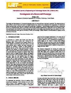
The servos operate using feedback to compare the current position into an input pulse width, which typically repeats every 14 to 20 ms (milliseconds). If the pulse width lasts for approximately 0.6 ms, the
ASME Southeastern Region XI Technical Journal, Volume 3, April 2004; also presented at the ASME Southeastern Region XI Technical Conference, Mobile, Alabama, April 1-4, 2004. servo will rotate to a maximum position [13]. If the pulse width is increased to approximately 2.4 ms, the servo will rotate to the opposite maximum position. A 1.5 ms pulse will set the servo in the middle (neutral) position. The servo shown in Fig. 7 uses an indirect drive potentiometer for feedback to determine positions. The servos are designed to rotate approximately 45 degrees in either direction from center for a total of nearly 90 degrees.
Figure 9. Servo timing diagram
Figure 7. Servo motor FP-S148
The servo in Fig. 7 is designed to use with model airplanes and cars, but when used with the servo controller SV203, it can be made to perform in various systems such as joysticks, mini-robotics, animatronics, and computer motion control. A sectional view of the servo motor FP-S148 is shown in Fig. 8. The SV203 controller produces a signal that allows the user to take advantage of a greater than the full motion range of most servos. The signal produced by this board allows the servo to rotate approximately 90 degrees in either direction from center for a total of nearly 180 degrees. Fig. 9 depicts the servo-timing diagram for the servo motor FP-S148.
The servo port connectors use a 3-pin male SIP (Single Inline Pin) connector (0.1-inch spacing). The servo connector is designed to be used with Futaba-type servos with J-type connectors. The servos have three colored wires: Black for ground, red for power, and white for signal. SERVO CONTROLLER The SV203 (Fig. 10) is a microchip PIC16C73 microcontroller based servo motor controller board manufactured and marketed by Pontech. It accepts RS232 (Recommended Standard Number 232) serial data signal from a host computer and outputs PWM (Pulse Width Modulated) signal to control up to eight RC servomotors (servos used in radio-controlled model airplanes, cars, etc.). Unused servo pins can be reconfigured for digital output to drive on/off devices. LED (Light Emitting Display) can be driven directly by the pins but devices such as relays and solenoids may need a simple transistor driver circuit [14]. There is also a 5 channel A/D port for reading analog voltage between 0-5 volts, and a SPI (Synchronous Peripheral Interface) port which allows data to be shifted in or out serially.
Figure 8. Sectional view of servo motor FP-S148
Figure 10. SV203 Controller board
ASME Southeastern Region XI Technical Journal, Volume 3, April 2004; also presented at the ASME Southeastern Region XI Technical Conference, Mobile, Alabama, April 1-4, 2004. The SV203B/C has the added feature of being able to run a standalone BASIC program on board, an 8K EEPROM (Electrically Erasable Programmable Read Only Memory). An optional IR (Infra Red) Receiver /Transmitter (IR 100) is also available to allow infrared serial communications. A 5 channel, 8-bit A/D input is available to read analog voltages between 0 to 5 Volts. Devices such as an analog joysticks or potentiometers can be connected to this port and the position can be read by the PC and sent back to the board to control the servo position. Fig. 11 illustrates how a servo is connected to a servo controller board.
fairly quickly. The form view of the servo control is represented in the Fig. 12.
Figure 12. Servo control form view
The developed program is used to verify whether the motors run correctly. We can control up to 8 servo motors with this program. The computer sends RS232 signal to the SV203 micro controller i.e., the microcontroller accepts RS232 signal as input data and outputs PWM signal to run the servo motors. Figure 11. Servo connected to SV203
SENSORS Sensors can be described as devices used to measure physical parameters and the algorithms for interpreting sensor data. Sensors can be grouped into two: internal and external sensors. Internal sensors are used to measure variables within the robot, joint angles, wrist forces, platform velocities, and external sensors to measure variables such as range, vision and voice. Sensor capability in each activity is essential for a robot to work in an unstructured environment, where it has to respond to changes in that environment. A typical sensor consists of a transducer and an electronic circuit [15]. Several types of sensors that are useful for robotic applications are: Position sensors, tachometers, range sensors, proximity sensors, tactile sensors, and vision sensors.
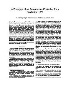
PLATFORM DESIGN Among the developed 1-DOF FRMC concepts, we have chosen the direct drive mechanism, which is judged to be more efficient than others. We believe that we can satisfy the goal of a compact design with a 1-DOF device whose size and motion are similar to that of a PC mouse. Since fingers will manipulate the device, it should be capable of producing a maximum force reflection of about 3 to 5 lb. In this concept, the joystick is directly attached to the actuator’s shaft. The direct drive mechanism is as shown in Fig. 13.
SOFTWARE In order to achieve quick and simple control over the hardware of the platform, a Visual Basic program was written to be able to control the platform when it is connected directly to a computer via the parallel port. This program proved extremely useful when testing the servos of the platform, as they allowed simple and fast control over the hardware and they could be modified
Figure 13. Direct drive mechanism
ASME Southeastern Region XI Technical Journal, Volume 3, April 2004; also presented at the ASME Southeastern Region XI Technical Conference, Mobile, Alabama, April 1-4, 2004. By using this concept of direct drive method in FRMC makes the design more compact and also more efficient as it directly couples to the joystick. The maintenance of this FRMC is inexpensive and the total cost for building it is also less costly compared to the other methods. By directly coupling the motor shaft to the joystick, we can have acceptably high torque and also smooth operation. Due to the direct linking of joystick to the motor shaft we don’t have any intermediate losses. We also don’t have any frictional losses or backlashes in this case. However, unlike the gear transmission and belt transmission systems, a direct drive system doesn’t reduce speed and also there is no torque amplification. 1-DOF FRMC PROTOTYPE SIMULATION Figure 15. Form view when robot is close to the obstacle
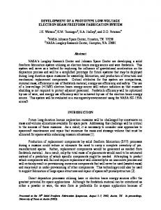
We have developed a program code in Visual Basic to show exactly how a 1-DOF FRMC operates. We have taken a PC mouse as our 1-DOF joystick (master robot), designed a car (representing a platform) on the PC monitor which is assumed to represent the slave robot and used an airplane icon (on the PC monitor screen) as an obstacle on the platform’s motion path. The form views of the program depicting snapshots of the screen are shown in Fig. 14 and Fig. 15.
When the user moves the mouse in the X-direction, the platform on the PC monitor moves accordingly. The program allows the user to set different positions for the obstacle. When the platform approaches the obstacle (plane icon) and if the user still tries to move the platform in the same direction, various color schemes (yellow and red) warn the user of impending collision. This mimics force reflection on the actual prototype. Later we have replaced the PC mouse with a 1-DOF joystick which is operated by using a servo motor and the remaining components are kept same. To control this joystick, we have used SV203 controller. This SV203 controller accepts RS232 (Recommended Standard Number 232) serial data signal from a host computer and outputs PWM (Pulse Width Modulated) signal to control the servo motor. We have used a potentiometer to identify the shaft position of the servo motor, which is connected to the A/D port of the SV203.
Figure 14. Form view when robot is away from the obstacle
When the joystick is moved in either of the directions, the platform (slave robot) on the PC monitor move accordingly. When the platform approaches the obstacle (the plane icon), various color schemes (green, yellow and red) warn the user of an impending collision. And if the user still tries to move the platform in the same direction, the operator feels the force reflection in the opposite direction so that the platform is moved away from the obstacle. After the platform is out of the collision area, force reflection is turned off and the current joystick position is set to zero position. We have developed both position and velocity control modes for this purpose. CONCLUSIONS In this paper, prototype development efforts for a 1DOF force-reflecting teleoperation system is presented. This has included a review of major components used
ASME Southeastern Region XI Technical Journal, Volume 3, April 2004; also presented at the ASME Southeastern Region XI Technical Conference, Mobile, Alabama, April 1-4, 2004. in the process of development, and the algorithms to control such a system. 11. Specifically, time-varying communication delays, which can be a major concern in this type systems, and position/force control algorithm structures were briefly discussed. A user-friendly graphical software package is developed to verify the test bed. The software incorporates features to run a servo motor using higher level languages. As future work, a Matlab® Simulink simulation for a 1DOF teleoperation in the face of time-varying communication delays will be developed. The outcomes of this simulation will also be verified experimentally. REFERENCES N. Xi, T.J.Tarn, “Stability Analysis of Non-time Referenced Internet-based Telerobotic Systems,” Robotics and Autonomous Systems, Volume 32, No. 2-3, Pages 173-178, August 31, 2000. 2. R.J. Anderson, and M.W. Spong, “Bilateral Control of Teleoperators with Time Delay”, IEEE Transaction on Automatic Control, AC-34, No. 5, pp. 494-501, May, 1989. 3. D. Drascic, “Skill Acquisition and Task Performance in Teleoperation Using Monoscopic and Stereoscopic Video Remote Viewing,” Proceedings of the Human Factors Society 35th Annual Meeting, San Francisco, pp. 1367-1371, September 1991. 4. P. Batsomboon, S. Tosunoglu, and D. W. Repperger, “Development of a Mechatronic System: A Telesensation System for Training and Teleoperation,” Chapter, Recent Advances in Mechatronics, Springer-Verlag, New York, pp. 304– 321, 1999. 5. N. Chopra, M.W. Spong, S. Hirche, and M. Buss, “Bilateral Teleoperation over the Internet: the Time Varying Delay Problem.” Proceedings of the American Control Conference, Denver, CO, June 46, 2003. 6. G. Niemeyer, and J. Slotine, “Stable Adaptive Teleoperation”, Int. J. of Oceanic Engineering, Vol. 16, No. 1, pp. 152-162, 1991. 7. M. I. C. Dede, “Position/Force Control of Robot Manipulators,” Master Thesis, Department of Mechanical Engineering, METU, Ankara, Turkey, April 2003. 8. H. Seraji, “Admittance Control: An Approach to Explicit Force Control in Compliant Motion,” IEEE Int. Conf. On Robotics and Automation, pp. 27052712, 1994. 9. W.D. Fisher and M.S. Mutjaba, “Hybrid Position/Force Control: A Correct Formulation,” Hewlett-Packard Company, October 1991. 10. G. Fodor and G. Tevesz, “Hybrid Position and Force Control Algorithm Expansion of a Robot Control
12.
13. 14. 15. 16.
1.
17.
18.
System,” Periodica Polytechnica Ser. EL. Eng., Vol. 43, No.4, pp. 251-261, 1999. E.G. Johnsen, and W.R. Corliss, “Human Factors Applications in Teleoperator Design and Operation,” John Wiley & Sons, Inc, New York, 1971. P. Batsomboon, and S. Tosunoglu, "A Review of Teleoperation and Telesensation Systems," Florida Conference on Recent Advances in Robotics, Florida Atlantic University, Boca Raton, Florida, April 1112, 1996. “Futaba Servo Motors,” accessed from www.futabarc.com/servos/futm0029.html, April 2003. Pontech SV203 Servo Motor Controller Board user’s manual, 2003. Also available online at www.pontech.com. P. J. McKerrow, “Introduction to Robotics,” University of Wollongong, Australia, 2001. P. Batsomboon, S. Tosunoglu, and D. W. Repperger, “A Survey of Telesensation and Teleoperation Technology with Virtual Reality and Force Reflection Capabilities,” International Journal of Modeling and Simulation, pp. 79–88, Volume 20, No. 1, 2000. J. Cui, S. Tosunoglu, R. Roberts and D. Repperger “A Review of Teleoperation System Control,” Florida Conference on Recent Advances in Robotics, Florida Atlantic University, Boca Raton, Florida, May 8-9 2003. R. A. Reyes and S. Tosunoglu, “On the Development of a Portable Three-Degree-of-Freedom ForceReflecting Manual Controller,” Florida Conference on Recent Advances in Robotics, Florida Atlantic University, Boca Raton, Florida, May 2000.