Development of a High-speed Multifingered Hand System and Its Application to Catching Akio Namiki
Yoshiro Imai
Masatoshi Ishikawa
Makoto Kaneko
Department of Information Physics and Computing, University of Tokyo 7-3-1 Hongo, Bunkyo-ku 113-8656, Tokyo, Japan {namik,yoshiro,ishikawa}@k2.t.u-tokyo.ac.jp Abstract— In this paper we introduce a newly developed high-speed multi-fingered robotic hand. The hand has 8joints and 3-fingers. A newly developed small harmonic drive gear and a high-power mini actuator are fitted in each finger link, and a strain gauge sensor is in each joint. The weight of the hand module is only 0.8kg, but high-speed motion and high-power grasping are possible. The hand can close its joints at 180deg per 0.1s, and the fingertips have an output force of about 28N. The hand system is controlled by a massively parallel vision system. Experimental results are shown in which a falling object was caught by the highspeed hand.
I. I NTRODUCTION In order to achieve a dexterous and skillful artificial hand, such as a human hand, various types of multifingered hands have been developed [1], [2]. Such hands were designed with attention to range of motion and accuracy, and less attention to speed of motion. Human manipulation consists of not only precise slow motion but also dynamic fast motion [3] in which the nature of the contact between finger and target changes dynamically. Examples of this dynamic change are “pushing”, “hitting”, “throwing”, “catching”, etc. A human takes advantage of such dynamic motion for manipulation. This is one of the reasons that a human manipulation is more dexterous and flexible than a robotic hand. To achieve such a dynamic fast motion in a robotic hand, we have developed a high-speed multi-fingered hand with a control system incorporating high-speed vision in which we address the problems of not only accuracy and range of motion but also speed of motion. In this paper we describe a newly developed high-speed hand system and its application to a catching task. II. BACKGROUND There has been considerable theoretical work on a multifingered hand addressed to: grasp stability, force analysis, and dynamic control [4]. But in most of this research static or quasi-static movement was assumed, and there has been little work on dynamic manipulation. The work on dynamic manipulation has been applied to juggling tasks using a simple manipulator, not complicated mechanisms such as a robotic hand [3], [5], [6].
Department of Engineering, Hiroshima Univ. 1-4-1 Higashi-Hiroshima-shi, Hiroshima, Japan
[email protected]
Various types of a robotic hands have been developed [1], [2]. In most hands a wire driven mechanism is used with control through high-power actuators that are placed outside of the main body of the hand [7], [8], [9], [10], [11]. But the mechanism is complicated and the total system is big and heavy. Recently several hands have been developed in which actuators are placed directly in each finger link. Several human-like robotic hands have been developed with this approach [12], [13]. These robotic hands have many degrees of freedoms to achieve the dexterous grasp of a human hand, but power and speed are not enough to achieve dynamic manipulation. Barrett Hand [14] is lightweight and powerful, but the number of degrees of freedom is not enough to achieve precise motion. On the other hand, in dynamic manipulation, transitions in the contact condition often occur when the fingers let a target go, or the fingers touch a target. It is difficult to observe a target only using force and tactile sense; vision plays an important role in this case. To observe a moving object in realtime, a high-speed vision system in which the sampling rate is more than 1 kHz is effective. Several types of vision chips have been developed [15], [16], and this technique was applied to a sensory-motor fusion system [17], and to produce high-speed grasping [18]. Our goal is to develop a high-speed multifingered hand system for dynamic manipulation with a visual feedback controller, and to build a theoretical base for dynamic manipulation based on the experimental results. III. L IGHTWEIGHT H IGH - SPEED H AND S YSTEM A. Design Philosophy In order to achieve the goal of dynamic manipulation our philosophy is maximization of the power and minimization of the mechanism. In particular three factors are important: (1) light weight, (2) high speed and high acceleration, (3) accuracy. In order to mount the hand on the end effector of a manipulator, the mass of the hand should be as low as possible. It is highly desirable that the hand weigh less than 1kg. Furthermore the low mass of the finger mechanism is desirable not only to achieve high-speed motion but for stable control.
Right Thumb
30
Index Finger
30 Left Thumb
(a) Top view
45
105
43.4
45
60
Actuator (MP)
φ20
φ17
30 Actuator (IP) Palm IP MP Joint Joint
Actuator (TM)
Wrist Part
(b) Left view 30 Right Thumb
30
Index Finger
Left Thumb TM Joint
38 Palm
Wrist Part
(c) Front view
Fig. 1.
Kinematic design
Fig. 2.
Photo of the hand
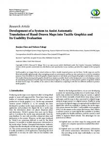
Both high-velocity and high-acceleration is required to achieve quick motion. Our goal is that each joint opens or closes at the rate of 180deg per 0.1s. This value is not derived from theoretical analysis but from our experimental results. We believe that this rate is sufficient to achieve dynamic motion. Another property needed for quick motion is accuracy. In order to achieve high-gain feedback control, backlash must be removed. B. Kinematic Design Fig. 1 shows the mechanical design of the hand, and Fig. 2 shows a photo of the hand. It has three fingers, and we call the fingers “left thumb’, “index finger” and “right thumb” looking from the left side. We call the joints of each finger, interphalangeal joint (IP), metacarpophalangeal joint (MP), trapezio-metacarpal joint (TM), corresponding to human anatomy [19]. In order to achieve the light mechanism, we reduced the number of joints and fingers as much as possible. We used three fingers, which is the minimum number to achieve a stable grasp. The index finger has 2 DOF (degrees of freedom), and the other fingers have 3 DOF, so that the hand has 8 DOF total. In general a hand needs 9 DOF to move a target to any position and orientation. But in our hand 1 DOF of the index finger is omitted, and the wrist joint of the manipulator takes its place. The fingers are arranged so as to grasp both circular and prismatic objects. Both left and right thumbs play the role of the “thumb” of a human hand. Each thumb has only 3 DOF which is less than the 5 DOF of a human thumb, but various types of grasping can be achieved because the TM joint can move in a wide range. C. Transmission mechanism High-speed motion imposes a heavy load on the finger mechanism. For this reason a simple mechanism should be used for reduction gear, transmission, etc. In most traditional hand systems a wire-driven mechanism is used. But this is not suitable for a lightweight mechanism, because it is large and complicated. In our hand a newly developed small harmonic drive gear and a high-power mini actuator are fitted in each finger link. A harmonic drive gear has desirable properties for control such as no backlash and a high reduction rate. As the transmission mechanism between actuator and joint, we adopt a bevel gear. This is because the axis of the actuator should be orthogonal to the axis of the joint, and a bevel gear is simple and strong enough to achieve high-speed rotation. Normally a bevel gear has a large amount of backlash. To reduce backlash the bevel gear was processed precisely, and defric coated on the surface. As a result, backlash of the developed bevel gear is small enough to control using high gain feedback.
4cm
D. Actuator In order to achieve “lightning” high-acceleration, we have developed a new actuator that allows a large current flow for a short time. Table I shows the specifications. The design is based on the new concept that maximum output should be improved rather than rate output. As a result this actuator can generate maximum power only for a short period of time (about 0.1s), but the power output is high. It has a coil with winding density more than 1.5 times other products. As a result, the torque per weight is more than 3.5 times other products. To prevent the actuator from overheating, the amount of current is controlled by software in realtime.
Active Vision 37,5cm
30cm
37,5cm Active Vision 40cm High-speed Hand
Fig. 3.
Visual feedback control system
TABLE I S PECIFICATION FOR THE DEVELOPED ACTUATORS motor type reduction rate max. speed [rpm] max. torque [Nm] size [mm] weight [g] sensor resolution[p/r]
IP DC brushless 50 300 0.245 φ14 × 36.6 25 100
Acquired image
MP,TM DC brushless 50 300 1.71 φ20 × 45.7 60 150
Fig. 4.
TABLE II S PECIFICATION FOR THE DEVELOPED ROBOTIC HAND
Active vision (with a CPV head) 2.0
Finger trajectory Desired trajectory
1.2
1.5
1
0.8 0.012 π −π 2 ∼ 2
MP TM 4.5 (*1) 28.5 (*2) 8 ≤ 800 0.8 no backlash 0.009 π −π 0 ∼ ±π 2 ∼ 2
(*1) IP = 0deg, and both IP and MP joints output maximum speed (*2) IP = 90deg, and the MP joint outputs maximum torque
E. Force Sensor The finger has strain gauges at the IP and MP joints for force control. The range of output is from 0.05Nm to 0.5Nm. In addition a 6-axis force/torque sensor and a tactile sensor will be mounted on each finger tip. F. Vision Sensor We added dual vision to the hand system as shown in Fig. 3. Vision is with a massive parallel vision system called CPV (column-parallel high speed vision system) [16]. It has 128 × 128 photo detectors with an all pixel parallel processing array based on vision chip architecture and an exclusive summation circuit for calculating moment values. Because the visual processing is executed in parallel in the processing array, high-speed visual processing (moment detection, segmentation, etc.) is achieved within 1ms.
Joint Angle [rad]
IP Max. speed (at tip)[m/s] Max. force (at tip)[N] Total DOF Weight [g] backlash [minute] Joint resolution [deg] Range [rad]
joint angle [rad]
1.0 0.8 0.6 0.4
0.5 0 -0.5
0.2
-1.0
0
-1.5
0.2
IP Joint MP Joint TM Joint
-2 0
0.1
0.2
0.3
0.4
0.5 time [s]
0.6
0.7
0.8
0.9
(a) Sine wave Fig. 5.
1
0
0.02
0.04
0.06 Time [s]
0.08
0.10
0.12
(b) Step Performance
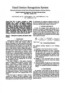
Early image processing in the CPV is performed in order to achieve segmentation of the image, extraction of the target area, and computation of the image moments. From these data, the position of the target is computed. Each vision sensor is mounted on an active vision, which has 2 DOF; pan and tilt, as shown in Fig. 4. Because the joint angle sensor has high resolution (0.0054deg), high resolution of 3D position sensing is achieved by fusing image information with joint angle information. The information acquired by the vision system is sent to the hand actuator at the rate of 1kHz, which is the same rate as the joint angle sensor and the joint torque sensor. IV. P ERFORMANCE Table II gives the specifications of the hand. It weighs less than 800g, yet it achieves maximum high-speed motion of 4.5m/s and high power of 28N at the fingertip. A. Response Each joint is controlled by PD feedback. Figure (a) shows the time response of the MP joint to a 10Hz
Power Grip
Circular Sphere
Prismatic Heavy Wrap
sine wave, which shows that the finger tracks the 10Hz wave with no discernible delay. Figure (b) shows the time response to a step input, which shows that the MP closed an angle of 180deg within about 0.1s. The IP joint closed this same angle in about 0.12s, and the TM joint closed an angle of 90deg within about 0.07s. The time to maximum speed was only about 0.01s in the IP and MP joint. It was about 0.02s in the TM joint. These results show that the hand achieves both high-velocity and high-acceleration. B. Grasping examination
Prismatic Medium Wrap
Centralized Index Ext.
Platform, Push
Distal Contact
Intermediate Grip
The main advantage of a multifingered hand is that it can grasp various objects by changing its shape. Several classifications of grasping have been proposed [19], [20]. In this proposal various grasps are classified into three large categories: a power grasp that passively resists arbitrary external forces exerted on the object, a precise grasp to manipulate the object, and an intermediate grasp in which some fingers are used for a power grasp and the other fingers are used for a precise grasp. We achieved these typical grasp types in our developed hand. The result is shown in Fig. 6. It is not always necessary that all types of grasping be achieved, but it is most useful to achieve dexterous manipulation. V. C ATCHING WITH T WO FINGERS Catching is one of the most important tasks for dynamic manipulation. In this section catching is shown using our high-speed hand with a visual feedback controller.
Tripod
Lateral Pinch
A. Catching strategy
Precision Grip
Circular Sphere
Circular Tripod
Prismatic
Prehension Thumb-Index
Prehension Thumb-Thumb
Fig. 6.
Prehension Latero-lateral
Grasping examination
To simplify the problem, suppose that the target and the hand are on a 2-dimensional plane, the target is a sphere, and the target is caught with two fingers. From various experimental trials, we have decided on the catching strategy shown in Fig. 7. Approaching phase: The fingertips approach the target surface corresponding to the free-falling motion of the target. Locking phase: The fingertips impact the target, and the target is moved to a stable grasp position. Finally the target is caught by two fingers, and the impact from both sides stops the falling motion of the target. Rebounding phase: The impact given to the target produces rebounding. As a result the fingertips are parted from the target surface, and the force at the tips becomes small. Holding phase: After rebounding is finished, the target is held in a stable grasp position. The proposed strategy may be called “active catching”, in which the target is held using the impact force. This has several advantages in comparison with “passive catching”,
in which the impact force between the target and the fingertip is kept as low as possible. In the active catching the hand may catch the target, which moves faster than the maximum speed of the fingertips. Furthermore, by changing the position and the orientation of the target, the hand may catch the target in the optimal position. In order to achieve active catching, precise and fast finger motion is needed. And the target or the fingertip should be soft. In this paper we used only a soft rubber ball.
(b) Locking
(a) Approaching
B. Catching control To simplify the problem we assume that the IP joint is always controlled at 90deg. In Fig. 8 r o ∈ R2 is the target position, r i ∈ R2 is the i-th tip position, and ei1 ∈ R2 and ei2 ∈ R2 are the unit vectors fixed on the finger link, R ∈ R is a target radius, and qi ∈ R represents the angle of the MP joint of the i-th finger. With two fingertips the optimal grasp points are both sides of the sphere: r o ± Rex , where ex is the x-axis unit vector. In order to bring the tip close to the point in the approaching phase, we define the following virtual constraints: ei1 T (r o + (−1)i Rex − r i ) = 0, (i = 1, 2).
(i = 1, 2),
(2)
where fi represents a nonlinear function. The desired trajectory of the MP qdi ∈ R is given as the solution of Eqn.2. It is written as qdi = gi (r o ),
(i = 1, 2),
(3)
where gi is the implicit function of fi . As a result, the control method is written as τi = Kp (gi (r o ) − qi ) − Kd q˙i ,
i = 1, 2.
Fig. 7.
ro - R ex
ro + R ex
R ro
d1 e12
(d) Holding
Catching strategy
d2 r2
r1
q1
L2 e22 q2
(1)
This means that the fingertips are always directed to the optimal grasp points, and it is regarded as the process to make a “virtual wall” along the trajectories of both fingertips. If the speed of fingertip is fast enough to track the target, the target falls along the virtual wall. For this reason, the locking and holding phases are also achieved. Because ei1 , ei2 , and r i are a function of the joint angle qi , Eqn.(1) is rewritten as fi (qi , r o ) = 0,
(c) Rebounding
(4)
where τi is the command torque of the MP joint, and Kp and Kd are appropriate scalars. Because the finger mechanism is light and the output of the actuator is high power, the inertia of the link almost can be ignored, and the PD feedback control achieves good performance. In the rebounding phase, it is desirable that the movement of the fingertips caused by the rebound is small enough. To solve this problem, the gain Kp is increased temporary in the moment both fingertips touch the target.
e11
Y
p1
O
X
p2
e21
L1
Virtual wall (trajectory of fingertips)
Fig. 8.
Catching algorithm
C. Experiment We used a rubber ball with radius of 4cm as a target, and we dropped it from about 1m in height. The speed of the falling ball is about 4m/s just before it hits the ground. In Fig. 9 the catching task for the ball is shown in a continuous sequence of pictures: approaching (0∼30ms), locking (30∼40ms), rebounding (40∼50ms), and holding (50ms∼). Fig. 10 shows the changes in the target position r o , and Fig. 11 shows the changes in the distance d1 and d2 . The success rate was more than 90% and tolerance of position error of the target was about ±2cm from the center of the palm. This experimental result is shown as a movie on the web site [23] or as a video [22]. Several types of failure modes were observed. The first type was that the fingertips could not touch the optimal grasp points in the approaching phase. It rarely happened after calibration had been achieved correctly. The second type was that the fingertips were parted from the target and the target fell down in the rebounding phase. This problem was solved by increasing the stiffness of the fingers. The third type was that the target was moved in a
wrong direction after impacting in the locking phase. The direction of a bounced ball depends on the coefficient of friction and restitution. It is difficult to know the accurate values of these parameters, but the errors in their measurement may be ignored if the speed of the fingertip is fast enough.
system, which consists of a dual high-speed multi-fingered hand-arm system, and a dual active vision system. In the future this new hand-arm system will be used for various types of dynamic manipulation. The need for a robotic hand that works in the real world is growing. And such a system should be able to adapt to changes in environment. We think that the concept of a high-speed hand system with realtime visual feedback will become an important issue in robotic research. VII. REFERENCES
0ms
10ms
20ms
30ms
40ms
50ms
Two finger catching
X-axis target potision [m]
0.03
0.09
X-axis position Y-axis position
0.02
0.08
0.01
0.07
0
0.06
-0.01
3.16
3.20
3.18
3.22
3.24
3.26
Y-axis target potision [m]
Fig. 9.
0.05
time [s]
Fig. 10.
Time response: target position
distance [m]
0.06
Distance 1 d1 Distance 2 d2
0.04
0.02
0.0 -0.01
3.16
3.18
3.20
3.22
3.24
3.26
time [s]
Fig. 11.
Time response: distance
VI. C ONCLUSION In this paper we have described a lightweight highspeed hand system, and the associated visual feedback control. We are now developing a high-speed manipulation
[1] R.A. Grupen et al. A survey of general-purpose manipulation. Int. J. Robot. Res., 8(1):38–62, 1989. [2] A. Bicchi. Hands for dexterous manipulation and robust grasping: A difficult road toward simplicity. IEEE Trans. Robot. and Automat., 16(6):652–662, 2000. [3] M.T. Mason and K.M. Lynch. Dynamic manipulation. Proc. Int. Conf. Intelligent Robots and Systems, pages 152–159, 1993. [4] K.B. Shimoga. Robot grasp synthesis algorithms: A survey. Int. J. Robot. Res., 15(3):230–266, 1996. [5] K.M. Lynch and M.T. Mason. Dynamic nonprehensile manipulation: controllability, planning, and experiments. Int. J. Robot. Res., 18(1):64–92, 1999. [6] A.A. Rizzi and D.E. Koditschek. Further progress in robot juggling: The spatial two-juggle. Proc. IEEE Int. Conf. Robot. and Automat., 3:919–924, 1993. [7] T. Okada. Object-handling system for manual industry. IEEE Trans. Systems, Man, and Cybernetics, SMC9-2:79–86, 1979. [8] J.K. Salisbury and J.J. Craig. Articulated hands (force control and kinematics issues). Int. J. Robotics Research, 1(1):4–20, 1982. [9] S.C. Jacobsen et al. Design of the Utah/MIT dextrous hand. Proc. IEEE Int. Conf. Robotics and Automation, pages 1520–1528, 1986. [10] T. Oomichi et al. Development of working multifinger hand manipulator Proc. IEEE Int. Workshop on Intelligent Robots and Systems, 873–880,1990. [11] M. Kaneko and T. Tsuji. Realization of enveloping grasp. Video Proc. IEEE Int. Conf. Robot. Automat., 1997. [12] H. Kawasaki et al. Dexterous anthropomorphic robot hand with distributed tactile sensor: Gifu hand II. IEEE/ASME Trans. Mechatronics, 7(3):296–303, 2002. [13] J. BUtterfass et al. DLR-hand II: Next generation of a dextrous robot hand. Proc. IEEE Int. Conf Robot. and Automat., pages 109– 114, 2001. [14] W.T. Townsend. The BarrettHand grasper – programmably flexible part handling and assembly. Industrial Robot, 27(3):181–188, 2000. [15] M. Ishikawa et al. A CMOS vision chip with SIMD processing element array for 1ms image processing. Dig. Tech. Papers of IEEE Int. Solid-State Circuits Conf., pages 206–207, 1999. [16] Y. Nakabo et al. 1ms column parallel vision system and its application of high speed target tracking. Proc. IEEE Int. Conf. Robot. and Automat., pages 650–655, 2000. [17] A. Namiki et al. 1ms sensory-motor fusion system. IEEE/ASME Trans. Mechatron., 5(3):244–252, 2000. [18] A. Namiki, T. Komuro, and M. Ishikawa. High speed sensorymotor fusion based on dynamics matching. Proceedings of the IEEE, 90(7):1178–1187, 2002. [19] I.A. Kapandji. The physiology of the joints. Vol 1. Upper limb. 5th ed. Churchil Livingstone, 1982. [20] M. R. Cutkosky. On grasp choice, grasp models, and the design of hand for manufacturing tasks. Proc. IEEE Int. Conf. Robot. and Automat., 5(3):269–279, 1989. [21] A. Namik and M. Ishikawa. Robotic catching using a direct mapping from visual information to motor command. Proc. IEEE Int. Conf. Robot. and Automat., 2003. [22] A. Namik et al. Dynamic catching using a ultra-high-speed multifingered hand system. Video Proc. IEEE Int. Conf. Robot. and Automat., 2003. [23] http://www.k2.t.u–tokyo.ac.jp/fusion/HighspeedHand/.