future connection to custom processing units to enable real-time processing of ... enable the development of a new generation of aperture domain signal ...
Development of a Parallel Acquisition System for Ultrasound Research Christopher M. Fabian*, Kailash N. Ballu*, John A. Hossack**, Travis N. Blalock*, and William F. Walker * ** * Dept. of Electrical Engineering, University of Virginia, Charlottesville, VA 22903 ** Dept. of Biomedical Engineering, University of Virginia, Charlottesville, VA 22908 ABSTRACT Medical ultrasound research is typically performed using either video image data, or summed Radio Frequency (RF) data. While such data has led to improved understanding of ultrasound image formation, and in the development of novel image formation and signal processing algorithms, it contains only a fraction of the information available in the individual beamformer channels before summation. This paper describes the development of an advanced experimental system which will simultaneously acquire RF data from 128 individual beamformer channels. We refer to such data, acquired across the transducer face, as aperture domain data. The system will be capable of continuous acquisition over a period of 1.6 seconds, the equivalent of 50 image frames. The system will also incorporate a data interface to allow future connection to custom processing units, ultimately enabling realtime processing of aperture domain data. The system will be constructed around a state of the art Agilent Technologies SONOS 5500 ultrasonic imaging system to enable real-time imaging and preserve broad signal bandwidth, high signal to noise ratio, and high dynamic range. The proposed system will facilitate research on adaptive imaging, system architecture, multidimensional blood flow estimation, broadband transducers, and a number of other areas. Keywords: ultrasound, medical ultrasound, signal processing, blood flow, phase aberration correction, medical instrumentation
1. INTRODUCTION Most existing experimental ultrasound systems are able to acquire a single beamformed line of Radio Frequency (RF) echo data per pulse transmission. This RF data is acquired prior to image formation, but after the data has been beamformed. Although this beamformed data provides researchers with more valuable data than a fully formed image, it contains only a fraction of the data that is available to the system as a whole. A parallel acquisition system, capable of acquiring data from all receive channels before beamformation would open new opportunities for experimental work and the development of novel signal processing methods. We are in the process of constructing such a system. We are developing a parallel acquisition system which will enable the simultaneous acquisition of RF data from 128 individual beamformer channels. This system will be capable of continuing this acquisition over a period of 1.6 seconds, the equivalent of roughly 50 images frames, or one full cardiac cycle. It will also incorporate a data interface that will allow for a future connection to custom processing units to enable real-time processing of aperture domain data. This system should enable the development of a new generation of aperture domain signal processing methods. The core of the system is an Agilent Technologies SONOS 5500 ultrasound system. The use of an existing commercial system ensures that the final experimental system will be appropriate for use in the clinic. Ultimately the development of this system will allow aperture domain signal processing to obtain new target data, enhance image contrast and resolution, and enable more accurate flow measurement.
2. MEDICAL APPLICATIONS 2.1 Adaptive imaging for phase aberration correction Conventional ultrasonic imaging systems calculate time delays for focusing and steering by assuming a uniform acoustic velocity of 1540 m/s throughout the body. However, the speed of sound in soft tissues is known to vary from approximately 1470 m/s in fat to over 1600 m/s in muscle1. Since soft tissues are geometrically complex, the speed of sound in a given region may vary considerably. Such variations, referred to as phase aberrations, degrade focusing during both transmission
and reception, reducing both spatial and contrast resolution and limiting diagnostic utility2-4. Phase aberrations are believed to cause significant image degradation in both the breast and heart, two areas of important diagnostic interest. While soft tissue speed of sound variations cause some image degradation, distortions induced by the skull make imaging almost impossible. The bone of the skull has a speed of sound of roughly 2500 m/s5 and varies in thickness from place to place. In addition, the skull exhibits a high reflection coefficient and is extremely attenuative6, 7. Thus, the skull induces not only phase aberrations, but also amplitude aberrations; that is, the amplitude of the received echoes may vary substantially across the face of the transducer. Attempts to image the brain through the intact skull with conventional systems yield unrecognizable images. A broad variety of algorithms have been proposed to compensate for phase aberrations8-11. The simplest8-10 apply differential focal delays to align the echoes received by each element with some reference signal. Clearly, these correction schemes require access to data from individual transducer elements. Since such data has not been available to academic researchers, they have acquired data sequentially from groups of elements, assuming that there was no tissue motion during the period of data acquisition. In some cases, excised tissue samples have been studied, eliminating motion as a possible problem, but opening questions about possible tissue degradation, and possible artifacts from water tank measurements. When groups have worked in vivo they have limited their efforts to regions where tissue motion due to respiration, circulation, and cardiac motion can be minimized. The impact of delay based adaptive imaging techniques is limited by a number of factors. First, the echoes received across the array exhibit significant spatial decorrelation12. This decorrelation fundamentally limits the accuracy of speckle signal alignment13. In addition, aberrations induced by the tissue may vary rapidly within the aperture plane, resulting in significant aberrations across the face of even a single array element14. Finally, simple time delay correction methods cannot compensate for frequency dependent or amplitude based aberrations. Each of the limitations described in the previous paragraph can be addressed through careful system and algorithm design. First, variations of the aberrator across the face of a single element can be reduced by forming an array using elements that have a largest dimension of less than 1/5 of the spatial autocorrelation length of the aberrator14. Second, the fundamental differences between received signals at different elements can be reduced or even eliminated by applying the translating apertures algorithm15. Finally, by decomposing received echoes into their constituent frequencies and applying amplitude and phase aberration correction simultaneously, it should be possible to compensate for arbitrary aberrations11. Proposed phase aberration correction methods adjust time delays in both transmit and receive operation. While correction on receive is technically challenging, it requires no iterative transmission and only limited feedback. Correction on the transmit side is more complicated however as existing systems are not amenable to rapid transmit timing adjustment. In early stages of our work in this area we do not intend to apply transmit correction. Rather we will take advantage of the improved beamforming of harmonic imaging and apply correction on receive only. Initial results from Gauss and Trahey suggest that this approach might prove valuable16. We intend to use the newly designed system to measure phase aberrations in a broad range of anatomical locations including the heart, where excessive motion has made earlier in vivo measurement impossible, and the skull, where aberrations are believed to be severe. We feel that such data will offer new insights into the in vivo characteristics of phase aberrations and will inform the development of new phase aberration correction algorithms. These new algorithms can be tested using in vivo data, and images made before and after correction. 2.2 Multidimensional blood flow estimation Most conventional blood flow measurement techniques estimate blood velocity by quantifying shifts in the phase or arrival time of the summed echoes received from moving red blood cells. These techniques are unable to measure the true blood velocity vector, but rather measure the projection of the true 3-D velocity vector along a line extending from the transducer through the target17. Thus, these techniques measure a blood velocity that varies depending upon the angle of the true motion relative to the transducer. Because this Doppler angle is estimated by the user, conventional systems yield measurements with large potential errors. This reduces the utility of these techniques, especially in areas where there is a limited acoustic window. The dependence of perceived motion on the Doppler angle has another more subtle effect. Since current phased array systems use relatively large transducer arrays, the effective Doppler angle may vary considerably across the face of the array. Thus, the process of summation combines signals with different relative phase or time delay shifts, effectively introducing noise
into the received signals. In addition, the slight variations in the echo pattern across the array that are observed in phase aberration correction12 also degrade the effective signal strength. To circumvent problems associated with changes in the Doppler angle and in the received echoes across the array, we have devised a set of new blood flow measurement algorithms. These aperture domain velocity estimators operate on data from individual array elements, before summation18. They utilize the variations in Doppler angle across the array as a source of information, enabling measurement of a 2-D velocity vector, rather than a simple 1-D estimate when using conventional linear arrays. When implemented on 2-D arrays, these algorithms may be able to estimate the complete 3-D velocity vector. Not only do these new algorithms offer more information than existing techniques, it may be of much higher quality. In computer simulations we have found that our techniques were as much as ten times more accurate than existing methods18. The development of the parallel acquisition system will allow data to be acquired from tissue mimicking phantoms and human subjects to test the potential of our novel flow estimation algorithms. The data acquired by this system will also enable us to compare our method with numerous alternative approaches19-22. 2.3 Tissue elasticity imaging In the past decade numerous techniques have been proposed to non-invasively image mechanical properties. The vast majority of these methods apply external forces and use ultrasonic imaging methods to track the displacements induced by these forces23-28. These elasticity imaging techniques can be divided into two classes, static and transient methods. Both approaches can possibly be improved through the use of aperture domain data acquired by this system. In static elasticity imaging an external compressor is applied to the tissue surface and ultrasound images are obtained before and after compression. By tracking the displacements induced by the compressor, it is theoretically possible to estimate the tissue elasticity properties. The accuracy of this approach is compromised however by a variety of artifacts. First, compression of the tissue alters the spacing of acoustic scatterers, thereby decorrelating the received speckle pattern and increasing errors in displacement estimates13. Second, the induced tissue deformation generally causes lateral as well as axial tissue displacement. Such lateral motion is difficult to estimate with conventional methods, and introduces uncertainty in the elasticity estimates. Both of these artifacts can be addressed by processing aperture domain data. Speckle decorrelation can be reduced through the application of companding29, 30, effectively compressing or expanding image dimensions. Companding could be carried out effectively using aperture domain data. Lateral tissue displacement could be readily estimated using any of the multidimensional velocity estimation techniques that have been developed for blood velocity estimation18-22. Transient elasticity imaging methods apply either sinusoidal or pulsed forces to the tissue surface and use ultrasonic methods to track resulting displacements. A potential source of error in these methods is the lateral motion induced by the propagating mechanical wave. As with static methods, these errors can be reduced through the application of multidimensional motion estimators. Another possible source of error results from the finite time required to acquire ultrasound image data. In some cases this acquisition period may be significant compared to the time required for the mechanical wave to propagate through a region of interest. In these cases an unfocused transmit beam and dynamically focused aperture domain data can be used to implement extremely rapid image frame rates31, 32. In both static and transient elasticity imaging, aperture domain data offers the possibility to significantly improve performance and eliminate what would otherwise be “fundamental” limitations. 2.4 Coded excitation and high bandwidth transducers Pseudo random codes have recently been applied successfully to enable higher frequency diagnostic imaging to depths greater than would be possible without using codes32. Pseudo random codes may take the form of pseudo random sequences – such as Barker codes, paired Golay codes or ‘chirps’. Since these codes are long in a temporal sense they are susceptible to corruptions as a result of the conventionally applied dynamic receive focusing process. The system we are constructing allows a user to vary, in software, the receive focusing and receive aperture parameters in an arbitrary manner so as to investigate the receive focusing function and thereby determine an optimal tradeoff between the conflicting desires for a longer coded pulse (better receive signal enhancement) and a shorter pulse that performs better when using dynamic receive focusing delays. Our initial interest is in a special type of coded waveform described in Reference34. In this mode, low frequencies are focused to greater depths and higher frequencies are focused to shallower depths. In the future, we also plan to use the system to investigate the use of ultra-high bandwidth (>100% -6dB bandwidth) transducer arrays based on the phased transducer layer scheme described in Reference35. Various complex design tradeoffs
are required but ultimately we expect to be able to operate very high bandwidth transducer arrays with the experimental system. The versatility offered by a software based receive filter and focusing path will allow various aspects of high bandwidth signal processing to be investigated with freedom from the limited bandwidth available in current system hardware implementations. It is anticipated that very high bandwidth will result in significant enhancements in the areas of: 1) harmonic imaging (tissue and contrast agents), 2) spectral analysis (‘tissue characterization’) and 3) strain signal imaging (elasticity imaging).
3. PARALLEL ACQUISTION SYSTEM DESIGN The parallel acquisition system is based on the existing Agilent SONOS 5500 clinical imaging system. We will modify the current system beamformer, add new circuit boards, and an interface to a PC so that real-time parallel acquisition of 128 channels of data over a period of at least 1.6 seconds can be conducted. In addition, this system will contain an interface to allow 128 channels to be ported into future hardware for real-time aperture domain processing. The development of this system will avoid many of the limitations of existing research systems. First, our system will take advantage of an advanced analog design to maintain high dynamic range and high SNR. In addition the real-time imaging and flow capabilities of this system will provide excellent guidance during aperture domain data acquisition. Note that real-time imaging will not be disrupted during data acquisition. The system will be capable of acquiring aperture domain data over a period of time greater than one complete cardiac cycle. This will allow for phase aberration measurement in the heart, aperture domain flow and elasticity estimation, and the testing of integrated beamforming methods.
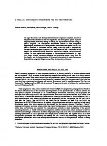
Figure 1: Diagram of parallel acquisition system. Gray regions represent new components added during this project. Points labeled A, B, and C represent common locations for data access. A block diagram of the system is shown above in figure 1. This diagram indicates the stages at which researchers typically acquire experimental data. Most investigators rely on the final displayed image (point C). Such images offer information about tissue structure and blood flow velocity. However, the acoustic echoes incident on the transducer have been processed non-linearly at a number of steps before they are displayed, making physics based signal processing impossible. At some leading institutions, researchers are able to acquire summed RF echo data at point B, before non-linear detection and display steps. This data has a high dynamic range and retains phase information. This beam-sum data has been employed in the development of signal processing algorithms for blood flow estimation, tissue structure characterization, and tissue elasticity estimation, among other applications. Although vastly more valuable than the data from point C, the beam-sum data contains
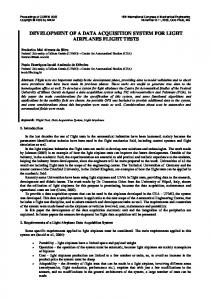
only a fraction of the data available to the system as a whole. Our completed system will acquire data from all beamformer channels by accessing data at point A, and will be capable of acquiring data from points B and C as well. The block diagram of figure 1 depicts the architecture of the proposed system. New components are shown in gray and existing parts of the SONOS 5500 are shown in white. Note that the transmit portion of the system is not shown for clarity. The standard SONOS analog receive stage acquires, filters, and amplifies echo data received by the transducer array. Analog signals are then routed to four beamformer boards and digitized at 10 bits at a rate of 40 MS/s. The beamformer boards are modified by adding daughter boards with digital latches and Channel Link (National Semiconductor) transmitters to transfer data to a memory board for acquisition. Details of the beamformer board modifications are described below. The memory board will contain 10.4 Gbytes of memory to store RF data during acquisition. Once this memory is filled, the board will transfer its data to a PC through a FibreXtreme interface (Systran Corporation). The design of the memory boards is described in greater detail below. The PC will initially store the received data in hard drives, but has the ability to archive the data to DVD-RAM disks. A diagram of the modified beamformer board is shown in figure 2. The layout and circuitry of the existing board is not altered at all by our modifications, rather new functionality is added by attaching daughter boards at the existing connections for the beamformer application specific integrated circuits (ASICs). This approach saves us the work of laying out new boards and greatly reduces the risk that our modifications would reduce signal quality. The ASIC beamformers located on these boards will be removed and daughter boards will be designed which attach at the solder pads for these parts. The daughter boards initially retime and buffer data at a rate equivalent to the sampling clock. The retimed registered buffer outputs are then routed to both the beamformer ASIC, located on the daughter board, and a set of Channel Link transmitters. The beamformer ASIC will therefore process RF data with one sample delay relative to normal operation. The ASIC outputs are then routed off of the daughter board to the rest of the system for image formation. The Channel Link devices will accept a parallel 28 bit input at a clock rate of up to 66 MHz and send out a serial differential voltage signal over 4 twisted pair lines. The use of Channel Link interfaces greatly reduces the number of wires needed to connect the beamformer boards to the memory board. In addition the Channel Link interface has an extremely low susceptibility to noise. The use of shielded, twisted pair lines should also reduce the electro-magnetic interference resulting from these high-speed data paths. Each of four beamformer boards will have 12, 28 bit Channel Link devices enabling parallel transmission of more than the necessary 320 bits at a rate of 40 MHz. While these interfaces will normally connect to a memory board for data storage, they will also enable the future addition of custom processing units to enable real-time aperture domain processing.
Figure 2: Block diagram of existing and new circuitry located on the SONOS 5500 beamformer boards. Elements with a gray background indicate circuitry that is located on a daughter board attached at the location of existing ASIC connectors. Note that RF data is sampled at 10 bits at 40 MS/s, and this rate and resolution is maintained through all stages of the system.
All four of the beamformer boards interface into a single memory board that is located within the SONOS 5500. This board will contain the 48 necessary Channel Link receivers needed to obtain data from all of beamformer boards in parallel. The outputs of these receivers are latched and routed under the direction of a Field Programmable Gate Array (FPGA) controller. This controller receives data from the archiving PC and observes data on the SONOS 5500 backplane to determine proper board configuration. After being latched and routed, the data from the beamformer boards will be sent in parallel to 20, 64 bit wide high-speed synchronous DRAM modules. These modules are utilized to enable continuous data flow without glitches due to memory refresh. The current design calls for 40, 256 Mbyte modules, allowing 1.6 seconds worth of data to be stored. After the RAM has been filled, and appropriate signals are received from the PC, the controller will configure the digital multiplexer and dump the RAM contents to the PC through the FibreXtreme interface. FibreXtreme is a high-speed interface capable of supporting data transfers at a continuous rate of 105 Mbyte/s. Thus, echo data acquired in 1.6 seconds will take just over one minute and forty seconds to be transferred to the PC. For experiments where only the data needed for a single image frame is acquired, the entire transfer should take just over 2 seconds. This high transfer rate will help to make acquisition of data in clinical settings comfortable and efficient. The computer end of the FibreExtreme interface is available as a PCI board and can be plugged directly into a PC slot.
Figure 3: Block diagram of the memory board located within the SONOS 5500. The components shown in the gray region at top are repeated in each of the three additional gray blocks. This board acquires data from the A/D converters through the Channel Link receivers and stores the data in RAM during real-time acquisition. Once acquisition is complete the controller dumps data from the RAM to the PC through the FibreXtreme interface. Note that critical SONOS 5500 backplane signals are acquired by the controller and archived along with RF data.
The final component of the parallel acquisition system is a high-end personal computer. The PC will acquire the RF data and the SONOS 5500 control signals through the FibreXtreme interface and archive the data for later processing. The system is tied to three 36 Gbyte hard drives, enabling storage of up to 10 full acquisitions. Three DVD-RAM drives will also be connected to the system to allow data archiving. Multiple drives are needed because at a write rate of only 1.3 Mbyte/s it will take roughly an hour and a half to write one 5.2 Gbyte disk. By using multiple DVD-RAM drives we will be able to archive data in a reasonable period of time. The main features of the proposed system are: - Acquire RF data from 128 parallel channels continuously for 1.6 seconds - Maintain full sampling rate and bit depth - Transfer full acquisition to a PC in 1.5 minutes - Transfer single frame acquisition to PC in 2 seconds - Acquire relevant SONOS 5500 control signals with RF data - Real-time imaging and flow before, during, and after data acquisition - Interface to allow future addition of real-time aperture domain processors - Memory controller is reprogrammable in situ - PC can communicate directly with memory controller - High SNR and dynamic range - System is easily configurable for specific experiments - Associated PC will have disk space to hold 10 full acquisitions The development of a parallel acquisition will extend a new level of experimental capabilities to academic researchers. We believe that access to single channel data, as enabled by our system, may yield major advances in acoustics and signal processing which would not otherwise be possible.
4. CONCLUSIONS The development of a parallel acquisition ultrasound system will allow for the acquisition of aperture domain data. Previously this aperture domain data had been unattainable to researchers that were using conventional ultrasound imaging systems. This system will be capable of storing a full 1.6 seconds worth of data, or approximately 50 full frames. It will also have a data interface that will allow for future processing of aperture domain data in real time. With the development of this system, it will be possible to use aperture domain signal processing to offer new target areas, enhance image contrast and resolution, and enable more accurate flow measurements.
ACKNOWLEDGEMENTS We would like to acknowledge the support of Agilent Technologies for their technical support and contribution of the SONOS 5500 ultrasonic imaging system. This work is supported by a Major Research Instrumentation Grant from the National Science Foundation (proposal 0079639).
REFERENCES 1. 2. 3. 4. 5. 6.
P. N. T. Wells, Biomedical Ultrasonics. London: Academic Press, 1977. M. O'Donnell and S. W. Flax, “Phase aberration measurements in medical ultrasound: human studies,” Ultrasonic Imaging, vol. 10, pp. 1-11, 1988. P. D. Freiburger, D. C. Sullivan, B. H. LeBlanc, S. W. Smith, and G. E. Trahey, “Two-dimensional ultrasonic beam distortion in the breast: in vivo measurements and effects,” Ultrasonic Imaging, 14, pp. 398-414, 1992. Q. Zhu and B. D. Steinberg, “Large-transducer measurements of wavefront distortion in the female breast,” Ultrasonic Imaging, 14, pp. 276-299, 1992. S. A. Goss, R. L. Johnston, and F. Dunn, “Comprehensive compilation of empirical ultrasonic properties of mammalian tissues,” JASA, 64, pp. 423-457, 1978. S. W. Smith, D. J. Phillips, O. T. von Ramm, and F. L. Thurstone, “Some advances in acoustic imaging through skull,” in Ultrasonic Tissue Characterization II, Pub. 525, M Linzer, Ed. Washington, D.C.: National Bureau of Standards, 1978, pp. 209-218.
7.
8. 9. 10.
11.
12. 13. 14. 15. 16. 17. 18. 19. 20. 21. 22. 23. 24. 25. 26. 27. 28. 29. 30. 31. 32. 33.
D. N. White, J. M. Clark, and M. N. White, “Studies In Ultrasonic Echoencephalography--VII: General Principles of Recording Information in Ultrasonic B- and C-Scanning and the Effects of Scatter, Reflection and Refraction by Cadaver Skull on this Information,” Medicine and Biology in Engineering, 5, pp. 3-14, 1967. S. W. Flax and M. O'Donnell, “Phase aberration correction using signals from point reflectors and diffuse scatters: basic principles,” IEEE Transactions on Ultrasonics, Ferroelectrics, and Frequency Control, 35, pp. 758-767, 1988. L. Nock, G. E. Trahey, and S. W. Smith, “Phase aberration correction in medical ultrasound using speckle brightness as a quality factor,” Journal of the Acoustical Society of America, 85, pp. 1819-1833, 1989. G. E. Trahey, P. D. Freiburger, and S. S. Worrell, “The 'Speckle Look-Back' Technique for 2-D Array Phase Aberration Correction,” in Eighteenth International Symposium on Ultrasonic Imaging and Tissue Characterization, Ultrasonic Imaging 15, M. Linzer, Ed. Rosslyn, Virginia, 1993, pp. 162. G. C. Ng, P. D. Freiburger, W. F. Walker, and G. E. Trahey, “A speckle target adaptive imaging technique in the presence of distributed aberrations,” IEEE Transactions on Ultrasonics, Ferroelectrics, and Frequency Control, 44, pp. 140-151, 1997. R. Mallart and M. Fink, “The Van Cittert-Zernike Theorem in pulse echo measurements,” Journal of the Acoustical Society of America, 90, pp. 2718-2727, 1991. W. F. Walker and G. E. Trahey, “A Fundamental Limit on Delay Estimation Using Partially Correlated Speckle Signals,” IEEE Transactions on Ultrasonics, Ferroelectrics and Frequency Control, 42, pp. 301-308, 1995. W. F. Walker and G. E. Trahey, “Aberrator Integration Error in Adaptive Imaging,” IEEE Transactions on Ultrasonics, Ferroelectrics and Frequency Control, 44, pp. 780-791, 1997. W. F. Walker and G. E. Trahey, “Speckle Coherence and Implications for Adaptive Imaging,” Journal of the Acoustical Society of America, 101, pp. 1847-1858, 1997. R. C. Gauss and G.E Trahey, “Adaptive Imaging in the Thyroid Using Fundamental and Harmonic Echo Data,” Proceedings of IEEE Ultrasonics Symposium, 2, pp. 1515-1519, Piscataway, NJ, 1999. J. A. Jensen, Estimation of Blood Velocities Using Ultrasound: A Signal Processing Approach. Cambridge: Cambridge University Press, 1996. W. F. Walker, “A New Class of Aperture Domain Flow Estimation Algorithms,” Proceedings of IEEE Ultrasonics Symposium, 2, pp. 1227-1231, Toronto, Canada, 1997. L. N. Bohs and G. E. Trahey, “A novel method for angle independent ultrasonic imaging of blood flow and tissue motion,” IEEE Transactions on Biomedical Engineering, 38, pp. 280-286, 1991. P. J. Phillips, “Real Time Two-Dimensional Vector Velocity Color Mapping System Using Subaperture Pulse Chasing,” PhD Dissertation: Duke University, 1996. M. E. Anderson, “Spatial quadrature: a novel technique for multi-dimensional velocity estimation,” Presented at IEEE Ultrasonics Symposium, Toronto, Canada, 1997. J. A. Jensen and P. Munk, “A new method for estimation of velocity vectors,” IEEE Transactions on Ultrasonics, Ferroelectrics, and Frequency Control, 45, pp. 837-851, 1998. R. Muthupillai, D. J. Lomas, P. J. Rossman, J. F. Greenleaf, A. Manduca, and R. L. Ehman, “Magnetic resonance elastography by direct visualization of propagating acoustic strain waves,” Science, 269, pp. 1854-1857, 1995. M. O'Donnell, S. Y. Emelianov, A. R. Skovoroda, M. A. Lubinski, and B. M. Shapo, “Quantitative Elasticity Imaging,” Proceedings of IEEE Ultrasonics Symposium, pp. 893-903, 1993. W. F. Walker, B. H. Friemel, L. N. Bohs, and G. E. Trahey, “Real-Time Imaging of Tissue Vibration Using a TwoDimensional Speckle Tracking System,” Proceedings of IEEE Ultrasonics Symposium, pp. 873-877, 1993. J. Ophir, I. Céspedes, H. Ponnekanti, Y. Yazdi, and X. Li, “Elastography: A Quantitative Method for Imaging the Elasticity of Biological Tissues,” Ultrasonic Imaging, 13, pp. 111-134, 1991. R. M. Lerner, K. J. Parker, J. Holen, R. Gramiak, and R. C. Waag, “Sono-elasticity: medical elasticity images derived from ultrasound signals in mechanically vibrated targets,” Acoustical Imaging, 16, pp. 317-327, 1988. Y. Yamakoshi, J. Sato, and T. Sato, “Ultrasonic imaging of internal vibration of soft tissue under forced vibration,” IEEE Transactions on Ultrasonics, Ferroelectrics, and Frequency Control, 37, pp. 45-53, 1990. P. Chaturvedi, M. F. Insana, and T. J. Hall, “2-D companding for noise reduction in strain imaging,” IEEE Transactions on Ultrasonics Ferroelectrics & Frequency Control, 45, pp. 179-191, 1998. P. Chaturvedi, M. F. Insana, and T. J. Hall, “Testing the limitations of 2-D companding for strain imaging using phantoms,” IEEE Transactions on Ultrasonics Ferroelectrics and Frequency Control, 45, pp. 1022-1031, 1998. S. Catheline, F. Wu, and M. Fink, “A solution to diffraction biases in sonoelasticity: The acoustic impulse technique,” Journal of the Acoustical Society of America, 105, pp. 2941-2950, 1999. L. Sandrin, S. Catheline, and M. Fink, “Transient elastography in biological tissues,” Journal of the Acoustical Society of America, 105, pp. 1014-1015, 1999. http://www.gemedicalsystems.com/rad/us/education/msut2.html
34. J. A. Hossack, “Extended Focal Depth Imaging for Medical Ultrasound” Proceedings of IEEE Ultrasonics Symposium, pp 1535-1540, 1996 35. J. A. Hossack and B. A. Auld, “Improving the characteristics of a transducer using multiple piezoelectric layers,” IEEE Transactions on Ultrasonics, Ferroelectrics, and Frequency Control, 40, pp. 131-9, 1993.