The MSS consists of two elements on the station, the Mobile Servicing ... purpose of the project is not to build actual ight hardware or software for the MSS but to ...
Development of a Real-time Laser Scanning System for Ob ject Recognition, Inspection, and Robot Control
1
F.R. Livingstone, L. King
J.-A. Beraldin, M. Rioux
Hymarc Ltd. 38 Auriga Drive Ottawa, Ontario, Canada K2E 8A5
Institute for Information Technology National Research Council Canada Ottawa, Ontario, Canada K1A 0R6
Abstract
A real-time laser scanner for object recognition, inspection, and robot control is presented in this paper. Range and intensity images are generated in perfect registration at a rate of 10 Mega-samples per second. Images have a resolution of 483 lines each having 512 pixels. Owing to its compatibility with the video standard RS-170, the range camera can be directly interfaced to an image processor through a video frame grabber with either an analog or digital input. The angular eld of view is 30o 2 30o. The stand-o� distance is 0.5 m and the operational depth of eld is 1 m. Furthermore, cooperative targets can be measured up to several meters away from the camera. The range resolution is 12 bits. Under normal operating conditions, a range precision of 0.2 mm and 2 mm are achieved at 0.5 m and 1 m respectively. The camera weighs only 2.75 kg. The source in the present system is a Nd-YAG laser emitting a laser beam with a wavelength of 1064 nm and a maximum power on the scene of 2 W. Future developments will include the use of a source at 1540 nm to make the system eye-safe. The testing of the prototype is well under way and soon, images of a variety of representative objects will be available. 1
Introduction
Canada is participating in the Space Station Freedom Program by providing a Mobile Servicing System (MSS) that will be used in assembling and maintaining the station as well as servicing and manipulating payloads and loading/unloading the shuttle. The MSS consists of two elements on the station, the Mobile Servicing Centre (MSC) and the MSS Maintenance Depot (MMD). Through the Strategic Technologies in Automation and Robotics (STEAR) Program, the Canadian Space Agency (CSA) is fostering additional technological development beyond the activity being undertaken by the MSS industrial team (SPAR, IMP, CAE, CAL, SED, MDA). The technical objective of one of the projects is to develop vision system technology for application to the control and operation of robotic systems. The purpose of the project is not to build actual ight hardware or software for the MSS but to develop technology that will meet the needs of the longer term growth and upgrading of the MSS. Concepts may be developed in an application area where the Contractor already has expertise, as long as the level of complexity or di�culty is comparable to that envisaged on the MSS. This paper describes a real-time laser scanner built by Hymarc Ltd. under contract to the CSA. The system is based on recent advances made at the National Research Council on such a system1 . The laser scanner generates registered range and intensity images according to the RS-170 standard. Compatibility to this video standard allows for a direct link to the Arti cial Vision Function (AVF) that is a key element of the MSS. Integration of the laser scanner to the AVF will allow three dimensional surveying of the robotic work-site, identi cation of known objects from registered range and intensity images, and object tracking based on range data. The investigation of algorithms for model-based tracking are reported in a separate article2 . The general requirements of the MSS are reviewed in Section 2. Section 3 discusses the need for vision in space robotics. An in-depth description of the scanner and its calibration are presented in Section 4. Finally, conclusions appear in Section 5.
1 NRC 35063{SPIE{Vol.2057 Telemanipulator Technology and Space Telerobotics (1993), pp.454{461.
1
MSS AVF* Tracking Control Mode
MSS Command Processing
Object EE AVF*
AVF* Command Processing
Camera/PTU Control
Camera
PTU
AVU**
AVF* Text/Graphics Display
MSS Command Processing
Image Processing
Video Switch
Camera
AVS Software
AVF* Video Display
Camera
Camera
Camera Laser Scanner
AVF* - Artificial Vision Function AVU** - Advanced Vision Unit
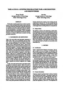
Figure 1: Impact of growth on basic AVF. 2
MSS Vision Requirements
The current AVF is based on the Space Vision System (SVS) that was demonstrated on CANEX-2. The SVS analyses video signals from the closed circuit television system of the space shuttle and provides real-time position/orientation and velocity information of an object with a cooperative target array3 . The baseline requirements for the Arti cial Vision Function (AVF) are as follows:
� � � �
To identify suitably illuminated objects (targets) from their video images. To estimate the position, attitude, translational rate, and rotational rate of the object. To provide appropriate camera control to track the object. To be able to track objects before capture by MSS manipulators and berth objects/payloads handled by manipulators.
The CSA intends to enhance the capabilities of the AVF by developing additional vision systems such as a laserbased range nding camera, as shown in Figure 1. The enhanced AVF will be capable of performing labelled and unlabelled object identi cation, shape determination of unknown objects, automatic target acquisition, update of world model database, and manipulator endpoint and link de ection sensing. These new features will be used in the following areas: enhanced target recognition in AVF tracking/berthing, world map veri cation for collision detection/avoidance, and object recognition and veri cation during automatic operations, e.g., truss assembly task. 3 3.1
Vision for Space Robotics
General
Computer vision will be integral to the success of the Space Station Project. The space environment is an open one, and events occur unexpectedly and with deviations from any pre-speci ed plan. Thus, sensory-based feedback is necessary, and vision is the sense through which some of the most valuable information about the environment is available. Space operations are also characterized by an overriding requirement for operational safety and reliability. Given the vast amounts of uncertainty that characterize most complex robotic operations and given their highly unstable nature, it follows again that large amounts of sensing data are required for reliability. To date, most sensing has been interactive. A human operator has direct visual feedback either through the cockpit windows or via a video imaging system mounted directly on the manipulators. While this may appear to be free of computational expense, the cost in manpower terms 2
is enormous and the e�ciency with which tasks are carried out is limited. Another point which characterizes the Space Station Project is that at the present level of planning, the amount of extra vehicular activity (EVA) required appears high. Thus, any technology likely to decrease this need will reduce operational costs and increase the safety of the astronauts. 3.2
Active versus Passive Vision
Vision involves the analysis of the properties of the luminous ux re ected or radiated by objects. To recover the geometrical structures of these objects, either to recognize or to track them through time, two basic vision strategies are available. One strategy, passive vision, attempts to analyze the structure of the scene under ambient light. In contrast, active vision is an attempt to reduce the ambiguity of scene analysis by structuring the way in which images are formed. By keeping the properties of invariance in rotation and translation of 3-D objects, sensors that capitalize on active vision can resolve most of the ambiguities found with 2-D imaging systems. Moreover, with structured light approaches, the 3-D information becomes insensitive to background illumination and to surface color and texture. Thus, the task of processing the 3-D data is greatly simpli ed. Triangulation-based laser range cameras are examples of vision systems built on such a strategy. For close-range space activities, a range camera based on triangulation with a single-spot scanning mechanism is recommended. Single-spot scanning is emphasized here because a typical scene in space will be high in contrast and will generate spurious re ections. These originate from the intense natural radiation eld caused mostly by the sun. Also, the thermal blankets used to protect some pieces of equipment are highly specular at the operating laser wavelength. Further, when the space station is in the shadow of the Earth, the vision system will have to operate in quasi-darkness. This situation calls for a camera that can operate over a wide dynamic range of intensities. Through the control of the camera parameters on a pixel to pixel basis, increased dynamic range of the range camera is achievable. Hence, range cameras based on single-spot scanning can be used in a longer time window during one orbit of the space station4. 3.3
Synchronized Scanning Principle
Rioux5 introduced an innovative approach to triangulation based range imaging by using a synchronized scanning scheme which allows very large elds of view with small triangulation angles without compromising precision. With smaller triangulation angles, a reduction of shadow e�ects is inherently achieved. Implementation of this triangulation technique by an auto-synchronized scanner approach gives a considerable reduction in the optical head size compared to standard triangulation methods. Range measurement and lateral position measurement are essentially decoupled and there is an improved ambient light immunity due to the small instantaneous eld of view. 4 4.1
Real-Time Laser Scanner
Vision System Electronics and Data Processing
Many issues a�ect the requirements for the signal processing hardware. The basic and key requirement is that the electronics provide range and intensity data at nominally 10 MHz. However, a nal design must address other issues, including design and manufacturing costs, system size, and power requirements. The underlying consideration, for any space or terrestrial product, is that the system has four basic functional elements: 1. Control of the polygonal mirror and y-axis scanner and generation of position and intensity signals at 10 MHz 2. Data acquisition, point processing (e.g., calibration) and intermediate storage - all in real time (10 MHz) 3. Image processing 4. Man/machine interface Each of these four main areas will require unique electronics to satisfy the technical requirements. However, many of these requirements are achievable, from a technical point of view, with technology readily available today. This is not to say that an implementation with today's technologies would be appropriate for a space environment, but rather that conceptually all tasks that must be accomplished could be realized. For example, control of the polygonal mirror 3
Laser Real-time Scanner
Polygon Controller
RS-170 Video Monitor
AAAAAAA AAAAAAA AAAAAAA AAAAAA AAAAAAA AAAAAAA AAAAAAA AAAAAA AAAAAAA AAAAAAA AAAAAAA AAAAAA AAAAAAA AAAAAAA AAAAAAA AAAAAA AAAAAAA AAAAAAA AAAAAAA AAAAAA AAAAAAA AAAAAAA AAAAAAA AAAAAA AAAAAAA AAAAAAA AAAAAAA AAAAAA AAAAAAA AAAAAAA AAAAAAA AAAAAA Local bus
n gU
alo
MAXbus
rd it it Ca Un e-8 e-8 h Un te tor tor an ter u c rap S S g h 7 p a a S n g i g g x xG m u -14 Co Me Me Ma Da Ma Tim ME V M it
An
AAAAAA AAAAAA AAAAAA AAAAAA AAAAAA AAAAAA AAAAAA AAAAAA
Console Terminal
VME bus
340M Disk Tape Drive
Figure 2: System architecture.
and y-axis scanner, scan synchronization, signal generation, analog-to-digital conversion, real-time calibration, and short-term high-speed storage are areas where solutions exist or technologies are readily available to create solutions.
The functional elements 2 and 4 are implemented on a MAXVideoTM family of image processing boards from Datacube. Figure 2 shows a diagram of the system architecture. The architecture of the real-time laser scanner is built around the industry standard VME bus, a Motorola 68040 general purpose CPU running under a real-time operating system OS9TM from Microware, some MaxVideoTM boards and 4 custom signal processing boards. At the moment, the image processing is done on a di�erent platform. Specialized hardware boards can be added in a later phase when all the algorithms required for the control and operation of robotic systems will have been fully investigated.
4.2
Video Rate Scanner
Figure 3a shows a schematic diagram that emphasizes the di�erent elements of the laser scanner. The raster type images are obtained in the following way. The laser beam is relayed to the polygon scanner through a series of focusing lenses. The rotation of the polygon imparts a scanning motion to the laser beam along the x axis. The scan along the y axis is achieved with a galvanometer (or motor). The re ected light from the scene is collected back through the mirror mounted on the galvanometer (or motor), a facet of the polygon scanner opposite to the projection of the laser beam, the collecting lens, and nally it impinges on a position detector where the information on depth and intensity is derived. The auto-synchronization e�ect is achieved by two facets of the polygonal mirror. In the RS-170 standard, a full image is composed of 525 horizontal lines (483 are active) which are displayed on a monitor in 1=30 second. Reproduction of a full image on a monitor is achieved by the sequential transmission of two interleaved elds at 60 Hz. The equivalent line rate is therefore 15750 lines/second. At a sampling rate of 10 MHz, 512 samples can be acquired per line. Due to the size of the collecting mirror, it is not possible to achieve the required 15750 scans/second using a galvanometer driven mirror or resonant scanner. The technology that can achieve this speed is a polygonal mirror driven at high speed by a motor. A polygonal mirror with N facets rotates the beam through 720o=N . A 30o scan angle will require a 24-facet polygon, which is one of the standards in the industry. To achieve video line rate, it must rotate at 15750=N revolutions per second, i.e., 656.25 rps. Such scanners usually rotate continuously in one direction at a xed speed to provide repetitive unidirectional scans. The mirror is mounted directly on the electric motor shaft. The combined inertia of the polygon and motor rotor contribute to rotational stability. This high inertia renders them impractical for applications requiring rapid changes in scan velocity. For true RS-170 compatibility, the galvanometer must be driven at 60 Hz. With this prototype, it is driven at 30 Hz (also known as progressive scan); the interlacing for display is addressed during post-acquisition processing.
4
Position Sensor
Source
Polygon Scanner
Source
Position Detector
β fo
Collimating Lens d
Imaging Lens
Galvanometer Scanner
γ
y
a z
Field of View
x
b)
a)
Figure 3: Schematic diagram of (a) complete optical arrangement, (b) main optical path unfolded. 4.3
Optical Design
With any laser-based range camera, depth of eld (DOF) and accuracy are related. Increased accuracy can be achieved by reducing the depth of eld. For robotic applications, a depth of eld of 1000 mm is reasonable, according to the technical literature and feedback from users of robots. Figure 3b shows the geometrical arrangement of the triangulation approach used here with the y-axis scanner removed for clarity. The laser beam is collimated and focused in the volume of view in such a way that the laser spot size is almost constant within it. To get maximum resolution from the imaging device, the desired depth of eld was matched to the Rayleigh criterion of a focused Gaussian laser beam. This leads to the following relationship, �a !o = (1) 2� where � is the wavelength of the source, a is the depth of eld, and !o is the radius of the focused laser spot at the center of the DOF. Using l = 1000 mm, a = 1000 mm and a source emitting at 1064 nm, one gets !o ' 0.41 mm. With a eld of view of about 400 mm at l = 1000 mm, then with a spot radius of 0.41 mm, more than 975 pixels can be sampled along the scan axis. In practice, 512 pixels per line are sampled in order to match RS-170-compatible image processing systems. The speci cations of the robotic vision system are summarized in Table 1.
r
The estimation of the required laser power is an important step in the design process. By taking into account the normal operating range of the position detector, a 2 W laser is required to measure surfaces with varying re ectance. A diode laser is preferred because of its size; the single-mode type gives better beam quality than multi-mode ones. At the present time, the maximum laser power available with this type of laser is 1 W. Because of the level of laser power required by this range camera, eye safety became important from the start of the project. Two possibilities had to be considered, i.e., either locate or design a position detector with a current gain mechanism (e.g., avalanche or micro-channel plate-based position sensitive detectors) or move to a safer operating wavelength. The latter solution was favored because of technical limitations of the previous devices. An InGaAs position detector sensitive at 1540 nm was selected6 . This continuous response detector produces two currents related to the position of the centroid of the light distribution impinging on its surface. The bandwidth of this InGaAs detector is 7.2 MHz, which meets the required video bandwidth of 4 MHz. In the visible spectrum, a fraction of a milliwatt is su�cient to cause eye damage, since the power of coherent light entering the pupil is magni ed, at the retina, through the lens, by a factor of roughly 105. At longer wavelengths, however, strong absorption by water present in the eye serves to reduce optical power reaching the lens, thus increasing the damage threshold. At 1540 nm the threshold power for eye damage is roughly 104 times greater than what it is in the visible spectrum. Also, the noise e�ective power of the InGaAs position detector is about the same as that of silicon-based position detectors. Furthermore, it was shown that scattering strengths of rough 5
Depth of eld (DOF) Stand-o� X-axis scan (at mid-DOF) Y-axis scan (at mid-DOF) Range precision Sampling rate Video rate: RS-170
min-DOF mid-DOF max-DOF Samples per line Lines per images Image rate
1000 mm 500 mm 400 mm 400 mm 0.2 mm 2.0 mm 12 mm 10 MHz 512 525 30
Table 1: Speci cations of real-time laser scanner. C D B
A
F
E
Figure 4: Concept for the scanner (not to scale): A=130 mm, B=70 mm, C=40 mm, D=70 mm, E=40 mm, F=190 mm. surfaces are similar at 1540 nm and in the visible region7. Thus, there is potential for signal improvement of 40 dB (optical) if 1540 nm is chosen instead of visible wavelengths for making eye-safe measurements. For this rst prototype, a Nd:YAG laser (1064 nm) was used instead of the erbium-doped ber laser7 because of the laser power required. At the present rate of development, however, it is reasonable to expect higher powers in the near future. The mechanical layout of a scanner for robotic vision is mainly determined by the space requirements of the polygonal mirror, drive motor, and the y-axis motor and mirror. A concept for the scanner is illustrated in Figure 4. The mirror/motor assembly is mounted on an optical bedplate which also supports all of the optical components and thus ensures a stable optical alignment. The laser input is from a bre optic connection and the beam is directed onto the polygonal mirror by a steering mirror. The portion of the casing that contains the y-axis motor and scan mirror has been made modular so that it can be removed and used as a single-axis scanner. The module could also be replaced by special lens assembly for a high accuracy version of the scanner. The dimensions of the range camera are given in Figure 4. The polygon motor, which is the heaviest component, weighs 0.6 kg. The range camera weighs about 2.75 kg. 4.4
Range Data Calibration
The range camera yields three quantities per sampling interval: two for the angular position of the mirrors and one for the position of the laser spot on the position detector. Owing to the shape of the coordinate system spanned by 6
these variables, the resultant images are not compatible with the coordinate systems used by most geometric image processing algorithms. A re-mapping of these variables to a more common coordinate system like a rectangular system is therefore required. The calibration is performed with a at plate composed of an array of targets that is positioned at known locations in front of the range camera with a precise linear stage. This plate is made up of evenly spaced targets on a grid of 11 2 13. Once the registered range and intensity images have been acquired for all the target array positions, the edges of those targets are extracted to sub-pixel accuracy using a moment preserving algorithm. The center of each target (in terms of the raw camera coordinates) is then determined by tting an ellipse to the edge points. An iterative nonlinear simultaneous least-squares adjustment method extracts the internal and external parameters of the camera model8. The re-mapping of the raw data to a rectangular coordinate system is done o�-line through software. Unfortunately, results could not be shown due to unforseen problems with the laser source. The testing of the prototype is well under way and soon, images of a variety of representative objects will be available. 5
Conclusion
This paper presented a real-time laser range camera for object recognition, inspection and robot control. The vision requirements for the Mobile Servicing System that will be developed by Canada through the Canadian Space Agency and its partners (industrial, university and research laboratories) were reviewed. The need for vision in space robotics was clearly identi ed. Particularly, a range camera based upon single laser spot scanning was identi ed as a very good strategy that can meet those vision requirements. The proposed system measures registered range and intensity images at 10 Mega-samples per second according to the RS-170 video standard, i.e., 483 lines with 512 pixels per line. With a stand-o� distance of 0.5 m, an operational depth of eld of 1 m, and a range resolution of 12 bits, the range camera will produce images adequate for various robotic tasks, e.g. collision detection and avoidance. Here, a rate of 30 images per second should provide enough data about the environment surrounding the robot. The control of the camera, the data storage and low-level point processing are implemented on a commercial platform. Future developments will include dedicated boards to perform the real-time correction and resampling of the images on a regular x; y grid. Also, software will be required to interpret the data and communicate its meaning to the system user. The particular tasks considered are object identi cation from surface structure, work cell modelling, and pose determination. Gathering the range data is only part of the solution in providing a vision system capability. 6
Acknowledgements
The authors wish to thank the Canadian Space Agency for the nancial and technical support along the course of this project. The authors wish to express their gratitude to G. Thompson for his technical assistance provided in the course of the system testing and L. R. Schmidt from the STEAR program for his valuable comments. Finally, the authors wish to thank E. Kidd for her help in preparing the text and P. Amirault for the technical illustrations.
References
[1] J.-A. Beraldin, M. Rioux, F. Blais, J. Domey and L. Cournoyer, \Registered Range and Intensity Imaging at 10-Mega Samples per Second," Opt. Eng. 31 (1), pp. 88{94 (1992). [2] W. Cheung, P. Letts and G. Roth,\Model-based Tracking using a Real-time Laser Range Finder," In Press, SPIE Vol. 2063 (1993). [3] S.G. Maclean, M. Rioux, F. Blais, J. Grodski, P. Milgram, H.F.L. Pinkney and B.A. Aikenhead, \Vision System Development in a Space Laboratory," SPIE, Vol. 1395, 8{15 (1990). [4] F. Blais, M. Rioux, and S.G. Mclean, \Intelligent, Variable Resolution Laser Scanner for the Space Vision System," SPIE, Vol. 1482, 473{479 (1991). 7
[5] M. Rioux, \Laser Range Finder based on Synchronized Scanners," Appl. Opt., 23, 3837{3844 (1984). [6] P. Maign�e, J.-A. Beraldin, T.M. Vanderwel, M. Buchanan and D. Landheer,\An InGaAs/InP Position Sensing Photodetector", IEEE J. of Quant. Electr., 26(5), 820{823, (1990). [7] M. Rioux, J.-A. Beraldin, M.S. O'Sullivan and L. Cournoyer, \Eye-Safe Laser Scanner for Range Imaging," Appl. Opt., 30(16), 2219{2223 (1991). [8] J.-A. Beraldin, S.F. El-Hakim and L. Cournoyer, \Practical Range Camera Calibration," In Press, SPIE Vol.2067, (1993).
8