Sensors 2012, 12, 11249-11270; doi:10.3390/s120811249 OPEN ACCESS
sensors ISSN 1424-8220 www.mdpi.com/journal/sensors Article
Three-Dimensional Laser Scanning for Geometry Documentation and Construction Management of Highway Tunnels during Excavation Vassilis Gikas School of Rural and Surveying Engineering, National Technical University of Athens, 9 I Polytechniou Str., Zographou, Athens 15780, Greece; E-Mail:
[email protected]; Tel.: +30-210-772-3566; Fax: +30-210-772-2728 Received: 19 June 2012; in revised form: 20 July 2012 / Accepted: 30 July 2012 / Published: 14 August 2012
Abstract: Driven by progress in sensor technology, computer software and data processing capabilities, terrestrial laser scanning has recently proved a revolutionary technique for high accuracy, 3D mapping and documentation of physical scenarios and man-made structures. Particularly, this is of great importance in the underground space and tunnel construction environment as surveying engineering operations have a great impact on both technical and economic aspects of a project. This paper discusses the use and explores the potential of laser scanning technology to accurately track excavation and construction activities of highway tunnels. It provides a detailed overview of the static laser scanning method, its principles of operation and applications for tunnel construction operations. Also, it discusses the planning, execution, data processing and analysis phases of laser scanning activities, with emphasis given on geo-referencing, mesh model generation and cross-section extraction. Specific case studies are considered based on two construction sites in Greece. Particularly, the potential of the method is examined for checking the tunnel profile, producing volume computations and validating the smoothness/thickness of shotcrete layers at an excavation stage and during the completion of excavation support and primary lining. An additional example of the use of the method in the geometric documentation of the concrete lining formwork is examined and comparisons against dimensional tolerances are examined. Experimental comparisons and analyses of the laser scanning method against conventional surveying techniques are also considered.
Sensors 2012, 12
11250
Keywords: laser scanning; LIDAR; tunnel excavation; total station; formwork; geometry documentation; construction management
1. Introduction Today, tunnel construction projects are faced with more complex design specifications, tougher quality control standards and narrower construction times together with increasingly tighter budgets than ever before. In such a highly demanding working environment the role of surveying engineering becomes a critical aspect to the success of a tunnel project from initially planning through completion and final acceptance. In particular, surveying operations that aim at geometric documentation of a tunnel are concerned with all phases of the construction lifecycle (i.e., excavation, completion of support measures, primary lining and tunnel commissioning). Besides, geometry documentation is of particular importance both to the contractor and the design engineers, and thus, it has a great impact on the technical as well as economic aspects of a project [1,2]. Traditionally, the surveying tasks relating to tunnel excavation operations have primarily relied on conventional surveying methods and to a lesser extent on photogrammetric techniques [3–7]. In the first category standard and reflectorless total stations are still extensively used to take profile measurements for design parameter verification and volume computations. More recently, specialized software applications have been made available that considerably automate field work and office calculations with a significant impact on operational efficiency and cost savings [8,9]. However, notwithstanding traditional surveying methods represent a flexible, precise and reliable solution to the problem they cannot provide a continuous representation of the tunnel surface. On the contrary, close range photogrammetry can provide image-based 3D models of a tunnel tube. Such models are produced using multiple images of an area suitably corrected for lens and perspective distortions [10]. For this purpose various processing techniques exist, ranging from stereoscopic vision of pair images to multi-convergent analysis supported by bundle adjustment. Nevertheless, although photogrammetric techniques offer a universal and relatively low-cost alternative, their use is less common in tunnel works due to the uneven wall surface and poor lighting conditions [11]. Also, despite the rapid advances on software tools that facilitate data collection and the processing cycle, stereoscopic plotting still requires expertise operators [10]. In recent years, the emergence of laser scanning technology has opened new perspectives for the recording and 3D reconstruction of a tunnel’s wall at the various stages of a construction program. Terrestrial Laser Scanners (TLS) use the reflection of a focused laser beam from objects to compute their location in 3D space. High resolution TLS can deliver millions of point locations with high (several millimeters to centimeter) accuracy in a short time and, in many cases, under rough field conditions. Their use in the underground space environment is suited to a wide spectrum of application areas, ranging from civil engineering [1,12], to cave modeling [13] and archaeological documentation [10]. Section 3 provides a summary of current use of TLS in tunneling applications. From this review it is evident that despite the rapid expansion of TLS in tunneling operations, there still exists a lot of unexplored potential that, if adequately developed, would benefit greatly the tunneling industry. In effect,
Sensors 2012, 12
11251
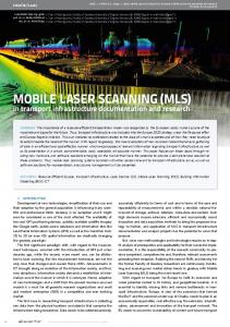
today, in spite of the many capabilities of TLS technology, the high cost of the equipment and the still developing algorithms for automatic data processing, along with the considerably long data acquisition times and complexity of data management might impose some practical constraints in certain cases. The scope of this paper is twofold; firstly, to provide a detailed review on TLS technology, to outline its applications in tunnel construction and to discuss the practical and theoretical issues arising during collection and processing of the scan data; and secondly, to expound the potential of TLS in geometric documentation of tunnels under construction through comparisons with traditional surveying methods. More specifically, three case studies are discussed: (a) multiple scanning at the tunnel face for computing over-cuts/over-breaks and for surface characterization; (b) scanning the tunnel corridor for producing profile sections and volume calculations; and (c) scanning the metal arch formwork for verifying its structural dimensions against nominal geometry. The scan data discussed in this paper come from two construction sites in Greece: (a) a motorway tunnel which is currently under construction in Central Greece and; (b) a newly constructed tunnel of the Athens suburban railway system. The paper is divided into six sections. Following the introduction, the second section provides an overview to the TLS surveying method with emphasis given on static systems, whereas, the third section provides a review on the applications and potential of TLS in tunnelling. In the forth section, the scanning and profile generation process is discussed, followed by a detailed presentation of the use of the method through case study scenarios. Summary and key conclusions are presented in the final section. 2. The TLS Surveying Method 2.1. Overview of the Method Terrestrial laser scanning enables the measurement and location of a large quantity of 3D points (known as the “point cloud”) in an automated manner and a very short time. In practical terms and in comparison to conventional surveying methods, the laser scanning technology offers a much higher point density data, an increased speed of data capture and the possibility for enhanced imagery and 3D visualization through specific processing and modeling tools. Also, compared to photogrammetric techniques, when complex and irregular objects of an uneven surface are to be documented the laser scanning method is usually the most appropriate option. Depending on the type of use, TLS can be operated either from a static position (mounted on a tripod) or from a dynamic platform (attached on a moving vehicle) [14,15]. In the first case, the TLS is used to produce a detailed map of the topographic features of the area around the static location that is occupied by the scanner, whereas in kinematic mode, it facilitates for conducting surveying and inventory maps of the corridor around the moving vehicle. The working principle of static TLS relies on repeated measurements of the slope range taken by an Electronic Distance Measurement (EDM) device at known angular intervals, which are defined at the horizontal and vertical planes passing through the origin of the EDM sensor. The outcome of this process is the spherical polar coordinates of the points in the field of view of the instrument in a local (topocentric) coordinate system. In contrast, in the case of kinematic laser scanning the device changes its position during data capturing. Therefore, a 3D point cloud emerges from the distance measurement, an angle measurement and the motion of the scanner [15]. Figure 1 offers a schematic view of the operation principle for both cases.
Sensors 2012, 12
11252
Figure 1. Working principle for the static (a) and kinematic; (b) terrestrial laser scanners.
(a)
(b)
The operational principle of TLS is similar to that of a robotic total station. However, TLS do not include an optical sighting assembly, and therefore they do not have the ability to measure on very specific ground features. On the contrary, the measuring head of the instrument is set to carry out distance and angular measurements over a pre-defined angular range and field of view. This operation is performed at constant angular increments the size of which is typically set by the user. In addition to 3D polar coordinates, the laser scanners can measure the reflection intensity of the targets in sight. Reflection intensity (i.e., the strength of returned laser beam) is greatly affected by the surface material, the angle of incidence and the distance between the scanner and the surveyed points. This information is critical in many applications, as it can be used to interpret predominant physical characteristics (such as roughness or material type) of the surface in question. Also, most laser scanners are equipped with a CCD camera, the location of which is precisely known with respect to the scanner’s electro-optical center by means of accurate calibration. In the early days of TLS technology, the CCD unit was used for sketching purposes in order to allow the user to identify specific objects within the field of view of the instrument. Today, CCD cameras are also used for mesh-texturing imagery purposes [16–18]. 2.2. Classification and Operating Principles of Static TLS Static TLS systems can be classified in various ways. Among them, the most the widely adopted approach in the published literature relates to the distance measurement technique that a TLS system employ. According to this sorting approach three principal methods exist, known as, triangulation, interferometry and time-of-flight methods [19,20]. The first technique operates on the basis of optical triangulation; that is, a light source (i.e., a single laser spot or a laser stripe) scans an object surface while its reflection is being recorded by one or more CCD cameras. The resulted distance is a function of the CCD inclination angle and the base-length defined between the CCD camera and the laser sensor. This method is accurate only over ranges of a few meters; and thus, is mainly used for industrial applications rather than in surveying engineering. In the second method, following the interferometric principle, an electromagnetic wave is split in two beams to produce an interference
Sensors 2012, 12
11253
pattern that, if analyzed appropriately, can lead to the measured distance. However, this approach is suited only for short, ultra-precise (sub-millimeter) distance and displacement measurements [17]. Most TLS systems used for engineering geodesy applications employ the time-of-flight method [14,17]. In this case, two operating principles for distance measurement are in use: the pulsed time-of-flight (direct time-of-flight), and the phase difference (indirect time-of-flight) principle. In the first approach, the distance from a TLS sensor to a feature point is determined by measuring the time it takes a laser pulse to travel to it and getting back to the sensor. Subsequently, its 3D polar coordinates are computed using the measured distance together with the horizontal and vertical angles registered in the instrument. In contrast, in the case of phase-based scanners, the ranging principle resides on the phase difference obtained between the transmitted and the received (backscattered) signal from the scanned points. This technique applies to laser systems that emit a continuous string of a laser beam, in a way that, a series of successive range measurements is obtained [14]. Table 1 provides an overview of the mathematical formulae underlying the two operating principles. Table 1. Mathematical formulae used to compute the distance measurement (d) and distance resolution (Δd) for the pulse-based and phase-difference TLS computational methods. Parameter distance (d)
Pulse-Based
Phase-Difference
t c⋅ 2
c Δφ ⎤ ⎡ ⋅ T ⋅ ⎢N + 2 2π ⎥⎦ ⎣
Notation t
flight time of light
T
period of modulated signal
c
speed of light in medium
Δφ phase difference between received and transmitted signal resolution (Δd)
c⋅
Δt 2
1 c ⋅ ⋅ Δφ 4π f
N
number of waves
f
frequency of modulated signal
Δt time resolution
From a practical perspective, the choice of a TLS depends on specific application needs that prescribe the technical characteristics of the scanner [19]. In general, the main features that characterize a TLS system are: the maximum observation distance, the scanning speed, the scanning resolution and the measurement quality (precision, accuracy and repeatability). As a matter of fact, these performance characteristics depend on the measurement method that a TLS employs. Thereby, the pulse-based scanners can measure long distances (in most cases