15 p. Abstract. Active noise control is a technique to cancel unwanted sound
using adjustable ...... rated into the music system in a Honda Accord station
wagon.
NS
• CH NOLOGY
S• V I S I O
IENCE
TE
C •S
EA
RCH HIG
HL
Jari Kataja
ES
Development of a robust and computationallyefficient active sound profiling algorithm in a passenger car
•R
IG
HT
5
VTT SCIENCE 5
Development of a robust and computationally-efficient active sound profiling algorithm in a passenger car
Jari Kataja
ISBN 978-951-38-7457-5 (soft back ed.) ISSN 2242-119X (soft back ed.) ISBN 978-951-38-7458-2 (URL: http://www.vtt.fi/publications/index.jsp) ISSN 2242-1203 (URL: http://www.vtt.fi/publications/index.jsp) Copyright © VTT 2012
JULKAISIJA – UTGIVARE – PUBLISHER VTT PL 1000 (Vuorimiehentie 5, Espoo) 02044 VTT Puh. 020 722 111, faksi 020 722 4374 VTT PB 1000 (Bergsmansvägen 5, Esbo) FI-2044 VTT Tfn. +358 20 722 111, telefax +358 20 722 4374 VTT Technical Research Centre of Finland P.O. Box 1000 (Vuorimiehentie 5, Espoo) FI-02044 VTT, Finland Tel. +358 20 722 111, fax + 358 20 722 4374
Kopijyvä Oy, Kuopio 2012
Development of a robust and computationally-efficient active sound profiling algorithm in a passenger car [Robustin ja laskennallisesti tehokkaan aktiivisen äänenprofilointialgoritmin kehittäminen henkilöautoon]. Jari Kataja. Espoo 2012. VTT Science 5. 77 p. + app. 15 p.
Abstract Active noise control is a technique to cancel unwanted sound using adjustable secondary sound. In active sound profiling, the target is to obtain a certain sound field or profile and the power over specific frequencies can be altered in a desired way, even by amplifying it. Active sound profiling can be used for increasing the sound quality in a passenger car, for example, by modifying the engine noise inside the car cabin. A fundamental algorithm in active sound profiling is the command-FXLMS (CFXLMS) algorithm, which is an extension of the famous FXLMS algorithm widely used in active noise control. The computational demand of the C-FXLMS algorithm becomes excessive in multiple-channel systems with engine noise components to be controlled using several loudspeakers and microphones. The most time-consuming part of the C-FXLMS algorithm is the filtering of the reference signals. In order to reduce the computational burden, a new way to modify the reference signals in narrowband systems has been developed in this work. Instead of conventional filtering operations, the new method is based on delaying the sinusoidal reference signals and modifying their amplitude. The algorithm should work reliably and maintain stability in all operating points. In this work, an adaptive leakage has been developed for the C-FXLMS algorithm to increase its robustness. The objective is to limit the adaptive filter coefficients at frequencies where the phase shift of the plant is large. Such phase shifts occur at resonances, for example, and the performance of the algorithm is drastically degraded. In this work, the C-FXLMS algorithm has also been combined with the EEFXLMS algorithm so that frequency-independent step sizes can be used. This increases robustness and enables faster tuning of the algorithm. The developed algorithm has been tested in a simulation model and in an experimental active sound profiling system installed in a car. The results prove that the algorithm works with sufficient accuracy. The convergence is fast and stability is maintained in all operating points.
Keywords
active noise control, active sound profiling, command-FXLMS algorithm, sinusoidal signal filtering, adaptive leakage factor
3
Robustin ja laskennallisesti tehokkaan aktiivisen äänenprofilointialgoritmin kehittäminen henkilöautoon [Development of a robust and computationally-efficient active sound profiling algorithm in a passenger car]. Jari Kataja. Espoo 2012. VTT Science 5. 77 s. + liitt. 15 s.
Tiivistelmä Aktiivinen melunvaimennus on menetelmä, jossa melua vaimennetaan säädettävällä vastaäänellä. Aktiivisessa äänenprofiloinnissa puolestaan on tavoitteena halutun ääniprofiilin saavuttaminen, jolloin tiettyjä taajuuksia voidaan jopa korostaa vaimentamisen sijaan. Aktiivista äänenprofilointia voidaan käyttää esimerkiksi äänenlaadun parantamiseen henkilöauton sisällä moottoriääntä muokkaamalla. Aktiivisen äänenprofiloinnin perusalgoritmi on command-FXLMS (C-FXLMS) -algoritmi, joka on kehitetty aktiivisessa melunvaimennuksessa paljon käytetystä FXLMS-algoritmista. C-FXLMS -algoritmi tarvitsee huomattavasti laskentatehoa monikanavaisessa muodossaan, jolloin useita moottoriäänen kerrannaisia muokataan usealla vastaäänilähteellä ja virhesensorilla. Suurimman osan laskentatehosta vie referenssisignaalien suodatus ja tehontarpeen vähentämiseksi on kehitetty uusi menetelmä sinimuotoisten referenssisignaalien suodatukseen. Uusi menetelmä perustuu signaalien viivästämiseen ja amplitudin muokkaamiseen. Algoritmin luotettavuus on myös tärkeä tekijä. Algoritmin pitää säilyttää suorituskykynsä kaikissa toimintapisteissä ja toimia stabiilisti. Robustisuuden parantamiseksi on C-FXLMS -algoritmiin kehitetty adaptiivinen vuotokerroin. Sen tarkoituksena on rajoittaa adaptiivisia suodinkertoimia toimintapisteissä, joissa järjestelmän vaihevaste muuttuu äkisti. Sellaisia muutoksia tapahtuu esimerkiksi resonanssitaajuuksilla, jotka aiheuttavat algoritmin suorituskyvyn heikkenemistä. Vuotokertoimen lisäksi C-FXLMS -algoritmi on yhdistetty EE-FXLMS -algoritmin kanssa, jolloin samaa askelpituutta voidaan käyttää kaikilla taajuuksilla. Se lisää robustisuutta ja nopeuttaa algoritmin virittämistä. Kehitettyä algoritmia on testattu simulointimallissa ja henkilöautoon asennetussa aktiivisessa äänenprofilointijärjestelmässä. Tulokset osoittavat, että algoritmi pystyy seuraamaan haluttua ääniprofiilia riittävällä tarkkuudella. Algoritmi myös suppenee nopeasti ja toimii stabiilisti kaikissa toimintatiloissaan.
Avainsanat
active noise control, active sound profiling, command-FXLMS algorithm, sinusoidal signal filtering, adaptive leakage factor
4
Preface Work related to this licentiate thesis has been carried out in an EU-funded InMAR project (Intelligent Materials for Active Noise Reduction) during 2004–2008 and in a VTT-funded ANRAC project (Advanced Noise Reduction and Alteration Concepts) during 2009. One of the main objectives in InMAR was to develop and construct an active sound profiling system in a passenger car. This objective was achieved in the project. In ANRAC, the system was further enhanced and the new algorithm was developed and tested. In InMAR, my work included studying active sound profiling algorithms and their implementation in Matlab/Simulink programming and simulation environment. The main work described in this licentiate thesis was done in ANRAC, in which the existing active sound profiling algorithm was enhanced to be more robust and computationally-efficient. My tasks included the development of the alternative method for reference signal filtering and the adaptive leakage factor. Together with my team members, the algorithm was programmed and its operation was evaluated in a simulation model. Finally, the algorithm was transferred to an experimental active sound profiling system installed in the passenger car. Implementation of the system and the experiments were mostly carried out by my team members. They also successfully tested the performance of the developed active sound profiling system. Jari Kataja Tampere, 22nd March 2012
5
Contents Abstract ........................................................................................................... 3 Tiivistelmä ....................................................................................................... 4 Preface ............................................................................................................. 5 List of abbreviations........................................................................................ 8 List of symbols ................................................................................................ 9 1.
Introduction............................................................................................. 11 1.1 Fundamentals of active noise control................................................. 11 1.1.1 Feedforward control ............................................................... 12 1.1.2 Feedback control ................................................................... 14 1.2 Active noise control in cars................................................................ 15 1.2.1 Control of narrowband noise .................................................. 16 1.2.2 Control of broadband noise .................................................... 19 1.3 Active sound profiling in cars............................................................. 20
2.
Feedforward active noise control ........................................................... 22 2.1 Adaptation algorithms ....................................................................... 22 2.1.1 LMS algorithm ....................................................................... 22 2.1.2 FXLMS algorithm ................................................................... 24 2.1.3 Eigenvalue-equalised FXLMS algorithm ................................. 25 2.1.4 Leaky FXLMS algorithm ......................................................... 26 2.2 Multichannel control .......................................................................... 27 2.3 Secondary-path modelling ................................................................ 28
3.
Active sound profiling algorithms .......................................................... 30 3.1 Narrowband noise cancellation/equalisation ...................................... 30 3.1.1 Single-frequency system ........................................................ 32 3.1.2 Multiple-frequency system ...................................................... 32 3.2 Command-FXLMS algorithm ............................................................. 34 3.3 Multiple-channel active sound profiling .............................................. 35 3.4 Reference signal generation ............................................................. 37
6
4.
Development of the active sound profiling algorithm ............................ 39 4.1 Reference signal filtering using lookup tables .................................... 40 4.1.1 Delay compensation .............................................................. 40 4.1.2 Reference signal filtering using magnitude and delay lookup tables ......................................................................... 42 4.1.3 Lookup-table based filtering using normalised magnitudes ...... 42 4.1.4 Creating lookup tables from the secondary-path model ........... 43 4.2 Adaptive leakage factor .................................................................... 43
5.
Simulation of the developed algorithm ................................................... 48 5.1 Simulation model .............................................................................. 48 5.2 Modelling of the plant and engine ...................................................... 49 5.3 System identification ......................................................................... 51 5.4 Performance of ASP and ANC algorithms.......................................... 53 5.4.1 Constant low RPM ................................................................. 53 5.4.2 Constant high RPM................................................................ 55 5.4.3 Increasing RPM ..................................................................... 57 5.5 Effect of reference signal filtering method .......................................... 59
6.
Experimental ASP system in a car .......................................................... 61 6.1 Active sound profiling system in a car ................................................ 61 6.2 Test results ...................................................................................... 62 6.2.1 Driving at constant speed ....................................................... 62 6.2.2 Acceleration........................................................................... 65
7.
Summary of contributions and conclusions .......................................... 69
Acknowledgements ....................................................................................... 72 References..................................................................................................... 73 Appendices Appendix A: Simulation results
7
List of abbreviations ANC
Active Noise Control
ANE
Adaptive Noise Equaliser
ANF
Adaptive Notch Filter
ASP
Active Sound Profiling
CAN
Controller Area Network
C-FXLMS
Command-FXLMS
DSP
Digital Signal Processing or Processor
EE-FXLMS
Eigenvalue-Equalised FXLMS
ECU
Electronic Control Unit
FFT
Fast Fourier Transform
FIR
Finite Impulse Response
FXLMS
Filtered-Reference LMS
IIR
Infinite Impulse Response
LMS
Least-Mean-Squares
LTI
Linear and Time-Invariant
LUT
Lookup Table
RPM
Revolutions Per Minute
8
List of symbols smoothing factor (in adaptive leakage factor) or gain parameter (in adaptive noise equaliser) difference in phase response (in adaptive leakage factor) leakage factor step size (n)
mean-square error delay [s] phase response angular frequency delay [samples] leakage factor matrix
a
scaling constant (in adaptive leakage factor)
c(n)
command signal
d(n)
disturbance
e(n)
error signal
e (n)
modified error or pseudo-error signal
f0
fundamental engine rotation frequency [Hz]
fs
sampling frequency [Hz]
s(n)
impulse response of the secondary path
w(n)
adaptive filter weight
x(n)
reference signal
x1(n)
reference sine
9
x2(n)
reference cosine
x (n)
filtered reference signal
y(n)
output signal
y (n)
filtered output signal
A
magnitude
J
number of reference signals or sinusoids to be cancelled
K
number of output signals or secondary sources
Lw
adaptive filter length
Ls
length of the secondary-path model
M
number of error signals or error sensors
P(z)
primary path
S(z)
secondary path
(z) (
secondary-path model )
FFT of the secondary-path model
T
sampling period [s]
W(n)
matrix of adaptive filter weights
W(z)
adaptive filter
W1(n)
adaptive notch filter weights for reference sines
W2(n)
adaptive notch filter weights for reference cosines
10
1. Introduction
1. Introduction 1.1 Fundamentals of active noise control Active noise control is a technique for attenuating unwanted acoustic disturbances by controllable secondary sources. The outputs of the secondary sources are arranged to interfere destructively with the disturbance from the original primary source. Successful application of active noise control requires that there is both a good spatial and a good temporal matching between the field due to the secondary sources, and that due to the primary source. The requirement for spatial matching gives rise to clear limits on the upper frequency of active noise control, due to the physical requirement that the acoustic wavelength must be small compared with the zone of control. The requirement for temporal matching requires a signal processing system that can adapt to changes in the primary noise. Active noise control works at low frequencies, up to 500–1000 Hz. where the acoustic wavelengths are long and passive noise control methods are inefficient. Active noise control is thus an excellent candidate for attenuating low frequency noise if the requirements mentioned above are closely studied [1], [2]. The components of an active noise control system include the secondary source, at least one sensor and the control system which is typically an analogue filter or a digital signal processor. The secondary source can be a loudspeaker or a structural actuator producing vibration. The sensors are microphones, accelerometers, tachometers or optical sensors. The primary noise can be broadband or narrowband. Broadband noise is caused, for example, by turbulence which is totally random. The energy of broadband noise is distributed over a large frequency band. Examples of broadband turbulence noise are low-frequency noise from jet planes and road noise inside a moving vehicle. By contrast, narrowband noise concentrates most of its energy at specific frequencies. Narrowband noise is related to rotating or repetitive machines and is periodic or nearly periodic. Examples of narrowband noise sources include internal combustion engines, turbines, compressors, pumps and fans [3]. The concept for active noise control was first introduced in 1936 by Paul Lueg, who patented his idea that unwanted sound in a duct could be cancelled with a loudspeaker [4]. In the 1950’s, the first active noise control systems were constructed. After that, the development of active noise control was halted for twenty
11
1. Introduction
years because of the lack of required technology. With the existing manual analogue techniques, it was extremely difficult to produce secondary sound that had the amplitude and phase required to attenuate the primary noise. The advent of the microprocessor in 1970’s made it possible to apply digital signal processing techniques and devices for active noise control and construct practical active noise control systems. Since 1970’s digital systems have developed enormously and become more affordable. Nowadays, active noise control has various applications, from active hearing protectors to active control of cabin noise inside aircrafts. Depending on the application, active noise control can be implemented using different control strategies, feedforward or feedback [5]. 1.1.1 Feedforward control Feedforward control is typically used when time-advanced information about the primary noise can be obtained. This information is called as the reference signal and is obtained by a reference sensor located near or inside the primary noise source. A feedforward active noise control system is shown in Figure 1. The reference signal is fed to the controller and processed to form an output signal that cancels the primary noise. A feedforward active noise control system is typically adaptive so that the controller is automatically tuned if the primary noise varies. In an adaptive system, an error sensor is used for detecting the residual noise. The signal from the error sensor, called as the error signal, is used to adapt the controller [3]. Primary source
Secondary source
Output signal
Reference signal
Error sensor
Error signal
Controller
Adaptation algorithm
Figure 1. Feedforward active noise control system. As an open-loop system, feedforward control is inherently stable. The algorithm can become unstable, however. Reference signal has to be coherent with the disturbance. Drawbacks are the acoustic feedback from the secondary source to the reference sensor if an acoustic reference sensor is used. The reference sensor has to be located far enough from the secondary source to ensure causality. This means that the processing time of the controller has to be less than the propagation time of the primary sound to the secondary source [3].
12
1. Introduction
The feedforward active noise control was first proposed in 1956 by Conover, who worked with active reduction of acoustic noise from large mains transformers [6]. The most famous application of active noise control is probably the feedforward active control of noise propagating in a ventilation duct. This application has been studied in various books and articles (e.g. in [1], [2], [3]) and also by the author [7], [8]. Even one of the fundamental papers about the famous and widely-used filteredreference least-mean-squares (FXLMS) algorithm deals with the active noise control in a duct [9]. Active noise control in a ventilation duct is illustrated in Figure 2. With a simple single-channel system containing only one reference, one error sensor and one secondary source, noise propagating downstream from the error sensor location can be attenuated if the diameter of the duct is small compared to the acoustic wavelength of the noise. Controlling higher order modes require a more complicated multichannel system [10].
Noise
Reference signal
Anti-noise
Output signal CONTROL SYSTEM Error signal
Figure 2. Active noise control in a ventilation duct. Feedforward active noise control has also been applied for attenuating engine noise inside car and aircraft cabins. Since a well correlated reference signal can be obtained by monitoring the engine, active noise control has typically been addressed with feedforward control. An active system in a cabin is a multichannel system containing several secondary sources and error sensors. In car industry, feedforward active control of engine noise has been applied to production cars by Lotus, Nissan Bluebird, Honda in variable cylinder management systems and hybrid vehicles and Toyota in hybrid vehicles [11], [12]. In propeller aircraft such as B.Ae. 748, Saab 340/2000, C130 Hercules and King Air series, active systems have been installed to attenuate propeller-induced cabin noise [13], [14]. Propeller-driven aircraft are prone to high noise levels which are related to the blade passage frequency of the engine. Active control of broadband noise inside jet aircraft has also been recently studied [15], [16]. Tractor and moving machinery cabin noise has been addressed in [17] and [18].
13
1. Introduction
1.1.2 Feedback control In feedback control, the error signal is fed back to the controller and used to process the output signal. A feedback active noise control system is shown in Figure 3. Primary source
Secondary source
Output signal
Error sensor
Error signal
Controller Adaptation algorithm
Figure 3. Feedback active noise control system. Feedback systems are typically fixed analogue systems or adaptive digital systems. A fixed analogue system can be efficiently built using analogue electronics. Another advantage is that no reference signal is required. Feedback systems have, however, several serious disadvantages. One disadvantage is that the control is not selective, i.e. any signal will be attenuated, not just those correlated with the reference signal. Another disadvantage is that the error sensor must be placed close to the secondary loudspeaker since the delay from the secondary source to the error sensor has to be kept minimal. The performance of feedback systems is limited by the stability of the feedback loop. Feedback systems may also suffer from spillover, also called waterbed effect, which causes amplification of noise outside the attenuated frequency band [1], [19]. The theory of feedback was first applied to active noise control by Olsen and May in 1953 [20]. They developed a device known as “electronic sound absorber” which improved sound absorption at low frequencies. Due to the limited distance between the secondary source and the error sensor, feedback active control is used in applications in which the zone of silence, i.e. the controlled space around the error sensor, can be relatively small. Applications in which feedback active control has proven to be useful are active headsets, active headphones and active hearing protectors. The principle of an active headset is illustrated in Figure 4. Such devices can be based on analogue or digital feedback control [21], [22]. Another area in which feedback active control has been studied is improvement of structural sound insulation by active means. For example, the sound insulation of aircraft cabin walls can be improved by using active panels [15].
14
1. Introduction
Figure 4. Active headset [22].
1.2 Active noise control in cars The acoustics of cars have always been an important marketing issue to car manufacturers, especially in luxury vehicles. Since 1980’s, active noise control has been applied to cars and some systems have even reached the mass-production level. There were several problems with the early ANC systems in cars, however, that prevented a broader use of such systems. The reasons were technical (absence of long-term experience, lack of understanding in robustness and reliability), commercial (cost of components) and legal (patent right issues). At the same time, passive noise control methods were successfully applied, although they usually added weight and fuel consumption [11], [12], [23]. During the last two decades, the situation has changed to favour the active methods. The concept of mechatronics (coupling electronics and signal processing with mechanical systems) has become more accepted in general. The cost for ANC systems has dropped dramatically, due to cheaper DSP hardware and the possibility to integrate the active system with the other systems already existing in cars (audio system, CAN bus). The loudspeakers may need to be upgraded for low frequency active control use. The microphones and associated wiring remain an additional cost for active control systems on some vehicles, although others already have microphones fitted as standard, for hands-free telephone operation, for example. The general experience with the ANC technology has grown and many long-standing issues with respect to robustness have been solved. The patents of the late 1980’s and early 1990’s have also expired. An important overall trend in the automotive industry is to improve the fuel efficiency of the vehicles by reducing weight. Reducing the weight of the body panels inevitably degrades their ability to attenuate low frequency noise and thus provides a real opportunity for active systems to be used for controlling the low frequency noise and vibration without significantly increasing weight [11], [12], [23].
15
1. Introduction
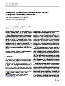
Figure 5. The sources of noise associated with a car [24]. There are many sources of noise associated with a car as can be seen in Figure 5. They can be divided into narrowband harmonic and broadband random noise. Narrowband noise sources include the engine, drive train, air intake, exhaust and auxiliary systems such as the radiator fan. Broadband noise is caused by roadtyre interaction and aerodynamic wind noise [24]. 1.2.1 Control of narrowband noise The fundamental source of narrowband noise in a car is the engine. Engine noise is radiated into the passenger cabin mainly via the air intake manifold. Other transfer paths include the bonnet panel through the wind screen, the bulkhead between the engine and the cabin and from the exhaust. The spectrum of the enginegenerated noise is composed of the harmonics of the engine firing frequency and engine rotation. In a four-cylinder car, the engine firing frequency is at twice the engine rotation rate. This second harmonic of the engine rotation frequency is called as the second engine order. The engine noise excites acoustic modes inside the passenger cabin, and in most mid-sized four-cylinder cars the dominant problem is the boom excited by the second engine order. A spectrum of the engine noise inside a car is given in Figure 6, in which the first order, the second order and other dominant orders are marked. The engine rotation rate is about 2000 RPM so the second engine order is at 2000/60*2 67 Hz.
16
1. Introduction
100
Magnitude (dB)
90 80 70 60 50 40 30 0
1st order
3.5th order 2nd order
50
5th order
4th order 100 150 Frequency (Hz)
200
250
Figure 6. Spectrum of the engine noise inside a car. For active control of the narrowband noise, the secondary sources can be located either in the cabin or at the air intake or exhaust outlet. With the latter approach, engine noise can be controlled for observers outside the car, not just those inside the cabin. Such system usually requires only one secondary source and a few error sensors, while a system inside the cabin requires several sources and sensors [24]. During the last decades, several systems for active engine noise cancellation inside the passenger cabin have been developed for production vehicles. The systems include: A system developed for a 1.1 litre 4-cylinder car by Lotus Engineering and ISVR in 1988. The system used 4 loudspeakers located in the dashboard and front doors (integrated into the car audio system) and 8 microphones mounted in the head lining. It controlled the engine firing frequency and its harmonics, and reductions of about 10 dB were measured in the front seats above about 3000 RPM. The improvement in the overall A-weighted sound pressure level was 4–5 dB. Reductions at lower speeds were measured in the rear due to the suppression of the first longitudinal acoustic mode, having a nodal line near the front passengers’ heads [12]. An almost identical system with the previous one implemented and massproduced by Nissan for Bluebird model in 1992 to cancel the second order engine boom. The system was separated from the car audio system and was relatively expensive. The car was available for a short time in the Japanese market only and did not find any direct successors [12], [23], [24]. An active system introduced by Honda in 2003 for a 3l iVTEC V6 engine with Variable Cylinder Management. In this engine, 3 of the 6 cylinders are temporarily deactivated. In the active system, active engine mounts are combined with an interior ANC system, which is integrated with the audio system. It uses 2 interior microphones but only 1 output signal which is distributed to both front and rear speakers with a fixed filtering. The ANC system focuses on the 1.5th engine order below 60 Hz. This system has been later utilised in many other Honda luxury models [23].
17
1. Introduction
A 3-microphone 3-speaker system by Toyota in its 2008 Crown Hybrid made for Japanese market only. The feedforward system is illustrated in Figure 7 where the controller, ECU, is connected to the audio system of the car. During slow city drives of between 20 to 40 km/h where the engine RPM is between 1000 to 3000 RPM, muffled noise at 50–150Hz can typically be transmitted to the car, impairing the car’s interior comfort. The active system is able to reduce noise levels by 5–8 dB [25]. An ANC system by GM in its 2010 GMC Terrain and the Chevrolet Equinox SUV, having 2 microphones and 1 loudspeaker [23].
Figure 7. Active noise control system for attenuating engine noise by Toyota [26]. Several experimental systems for engine noise cancellation inside vehicles have also been constructed. They include a system with 4 loudspeakers and 4 error sensors in a passenger car [27], a system using 6 secondary sources and 8 error sensors for a van [28], and a system in a truck cabin mock-up with 3 secondary sources and 3 error sensors [29]. Active systems for controlling the noise radiating from the engine air intake orifice has been developed and tested by Siemens Automotive [30]. The secondary source was placed inside the air intake and the error sensor was located near the loudspeaker. The feedforward system was tested in several 6- and 8-cylinder cars, with the reference signal taken from a tachometer in the engine. The radiated engine noise from the induction system was effectively eliminated over the control bandwidth, the power draw of the loudspeaker was minimal and the flow restriction of the actively controlled inlet was significantly reduced compared to the production air induction system. A similar system was developed by Hyundai Motors and Seoul National University [31]. An active intake control system for a 4-cylinder engine was constructed, with two loudspeakers placed on the side of the intake duct. As a result, maximum reduction of 30 dB was measured at the dominant 2nd
18
1. Introduction
order and 10 dB at the 3rd and 4th orders under stationary conditions and 20 dB at the 2nd order under sweeping conditions. Efforts have also been conducted to enhance robustness of the control algorithm of the active intake system under rapid acceleration [32]. The third way to control the engine noise is the active control of exhaust noise. With this approach, the active system can reduce the sound power output from the exhaust and may also improve the performance of the car by removing the need for current passive silencers [24], [33], [34]. Conventional silencers involve the use of a muffler system, which contains sound absorbing materials. It induces flow restriction and increased back pressure, which has a direct effect on the performance of the engine. Active exhaust noise control systems can be hybrid, including a simplified passive muffler and an active muffler, or totally active. Typically the systems include loudspeakers as the secondary source but also an electrically controlled valve has been used as the source [35]. Active vibration control has also been applied to vehicles for narrowband noise reduction. In vehicles with large engines and heavy duty trucks, the vibration from the engine can cause low-frequency booming inside the passenger cabin. In order to tackle this problem, active engine mounts adjusting the stiffness of the damping properties of the mount has been developed. Active engine mounts has been mass-produced by Toyota and Nissan. In 1997, Toyota developed an active mount based on feedforward control for reducing low-frequency idling boom in a V6 recreational vehicle. Nissan developed a similar system for diesel engines in 1998 [11], [24]. 1.2.2 Control of broadband noise Road noise is caused by interactions between the tyres of the car and irregularities in the road surface. Road noise is a strong contributor of unwanted sound power in many cars. The main processes of noise generation occurring within a rotating tyre are vibration of the tyre structure and acoustic phenomena caused by the tyre-road interaction. These noise sources combine to produce a broadband spectrum, which contains large amounts of energy in the sub-audio range [36]. The vibration of the tyres, as with most noise sources in a car, take more than one route into the passenger cabin. One such route is acoustic noise radiating from the tyres, which is amplified by the horn effect caused by the geometry of the tyre and the road, being channelled up through body panels on the car. Another route is structure-borne, in which vibration from the tyres is transmitted through the suspension and into the body structure. The primary path for the structural transmission is through the suspension mounts. Both transmission paths into the cabin result in the vibration of the car body, which leads to excitation of specific modes of different parts of the car. These include bending and torsional vibration of the whole body, “ring mode” vibration of the passenger compartment and bending modes of the engine and transmission, cabin acoustic resonances and body panel plate modes [24].
19
1. Introduction
Over the years many active control systems have been developed to deal with the problem of road noise [11], [12], [37], [38], [39], [40]. Many of the systems used feedforward techniques, with reference signals derived from accelerometers on the vehicle suspension and body [12]. In order to obtain reasonable levels of active control, it was found that about six reference signals were required. This is because the tyre vibration is relatively uncorrelated in its various degrees of freedom, and reference signals have to be used for all the significantly contributing sources. Although many of these systems were experimentally successful, there is often a long way to go from initial development to the production line. One system that has made it to production was developed at Honda in 2000 [40]. The system is based on combined feedforward-feedback control so that a feedback loop is used to control noise in the front seats of the passenger cabin, while the error microphone of the feedback system provides a reference signal for a fixed feedforward system to control the noise in the rear seats. The whole system is incorporated into the music system in a Honda Accord station wagon. This system is designed to control a 40–50 Hz boom caused by the excitation of the first longitudinal acoustic mode by road vibration. Estate cars are particularly prone to this phenomenon due to the increased length of the passenger compartment. The control system configuration is able to achieve a 10 dB reduction at low-frequency road noise in the region of the front passenger seat. The commercial success of this system is due to the reduction in cost that has been made over previous ANC car systems. This has been achieved by the elimination of expensive DSP hardware, by using feedback and fixed forward control strategies, rather than the more expensive adaptive feedforward control. Wind noise is a less significant source of random noise at low speeds than road noise, but becomes noticeable at high road speeds, approximately above 90 km/h. Wind noise is created by many different aerodynamic structures over the surface of a car, which excite a wide range of frequencies. These vary from low frequency noise produced by turbulence due to large-scale flow separation (6–100 Hz), to vortex shedding (at 100–500 Hz and 1000 Hz), leaking window seals (at 1000– 8000 Hz) and turbulent flow over door and bodywork gaps (2000–4000 Hz). Preliminary work was conducted by Lotus engineering and the ISVR (Institute of Sound and Vibration Research at University of Southampton) in the early 1990’s to create an adaptive feedback control system to reduce sound levels inside the cabin due to a low frequency tonal boom at a specific resonant road speed brought about by open sunroofs. The frequency of this resonance is dependent on both the volume of the cabin cavity and the size of aperture created by the open sunroof. At a frequency of 25 Hz, a reduction of 30 dB was achieved, although a slight increase in broadband noise was experienced [24].
1.3 Active sound profiling in cars A recent trend with the active systems in cars is the active control of the overall sound quality, instead of the pure sound level. Many cases arise in the control of
20
1. Introduction
sound quality when it is not necessary to completely cancel the sound field, but it is desirable to retain or even enhance specific frequencies of a given spectrum. This is often the case in the car industry, where the acoustic impression of a car can be altered by enhancing some engine orders and reducing others. The active control of sound quality generally involves a control system that drives the microphone signals inside the car towards a target, or command signal, instead of minimising it. Depending on the source, this has been termed noise equalisation, sound design/synthesis, sound/noise profiling and sound quality control. Recent trends also include the use of active control systems to provide a smoothly changing sound profile with engine speed, but with an emphasis on sporty sound during acceleration. Characteristics of different engine types could be an excellent starting point for designing the sound profile of a car. Depending on the number of cylinders and the engine configuration (straight or V-shaped), the engine noise may sound growly or smooth [41]. With sound profiling, it could also be possible to provide an acoustic environment inside the vehicle that encourages the owner to drive in a more fuel-efficient way, for example [12], [24]. Traditionally, enhancing the subjective engine sound quality has been tackled with passive, mechanical solutions while active approaches have not been taken into considerations even if they were viable and easier to implement [23]. Active sound profiling requires a substantial amount of digital signal processing and the hardware is often too expensive to be accepted by car manufacturers. During the last years, however, car manufacturers including Volkswagen, Mini, BMW and Audi have started to utilise active solutions for improving sound quality [23]. A prototype system has also been constructed in a Ford C-Max [42]. Active control of sound quality may become more important with the use of hybrid vehicles and in vehicles with variable cylinder management [43]. The quality of the sound inside these vehicles changes with the power source, which can be disconcerting to the driver. In conventional vehicles, certain noise phenomena are masked by the engine noise. In situations where the combustion engine is turned off in a hybrid vehicle, these noise components can become dominant and annoying [44]. This is a particular problem in electrical vehicles [45]. It is not yet clear how the interior noise of an electrical vehicle should sound like, but active sound profiling is an option for artificially generating the engine noise both inside and outside the vehicle. In hybrid concepts, the driving condition is often decoupled from the operation state of the combustion engine, which leads to unusual and unexpected acoustical behaviour. Pedestrian safety is also an issue with hybrid and electrical vehicles, since the electric motor operates nearly silently and the vehicle may not be heard by pedestrians. Lotus Engineering has addressed this problem in hybrid vehicles by projecting engine sounds externally to improve pedestrian safety [46]. The system also employs active noise cancellation to reduce noise inside the cabin.
21
2. Feedforward active noise control
2. Feedforward active noise control Feedforward control has already been introduced in Chapter 1.1.1. The objective of this chapter is to describe the algorithms used for adapting the feedforward controller in single-channel and multi-channel systems. The stability of the algorithms is also analysed.
2.1 Adaptation algorithms Algorithms for adapting the feedforward controller are considered. The algorithms are based on the famous LMS algorithm which minimises the mean-square value of the error signal. In active noise control systems, the influence of the secondary path from the secondary source to the error sensor has to be taken into account. The secondary path influences both the algorithm itself and the stability of the system. 2.1.1 LMS algorithm When discussing about adaptive filtering, the LMS algorithm is typically referred to as a standard algorithm. The LMS algorithm is based on the method of steepest descent in which the adaptation is done recursively using the gradient vector of the squared error. The LMS algorithm for adaptive noise cancellation is illustrated in Figure 8. The objective is to cancel the disturbance signal d(n) with the output of the adaptive filter, y(n). The error signal e(n), which is the sum of the disturbance and the adaptive filter output, is used for adapting the adaptive filter W(z) so that the error is minimised. In the adaptation, also the reference signal x(n) is needed. The reference signal contains information about the disturbance and thus correlates with it. If the reference signal is equal to the disturbance, the disturbance can be totally minimised. Otherwise, the disturbance is cancelled only at the frequencies where the signals correlate.
22
2. Feedforward active noise control
d(n) x(n)
y(n)
W(z)
e(n)
LMS algorithm Figure 8. LMS algorithm. The error signal is expressed as ( )= ( )+ ( )= ( )+
( ) ( ),
(1)
where w(n) is the filter coefficient vector and x(n) is the reference signal vector. In signal processing applications, the error signal is typically expressed as the difference of the disturbance and the output signal. In acoustic applications, however, the signals can be considered as interfering sound fields and summation of the signals is thus preferred. The mean-square error can be written as ( )= [
( )] = [
( )] + 2
( )+
( )
( ),
(2)
where p is the cross-correlation vector between the disturbance and the reference signal and R is the autocorrelation matrix of the reference signal. Equation 2 requires the computation of the cross-correlation vector and autocorrelation matrix, which becomes too time-consuming in a practical system with nonstationary signals. To overcome this problem, the method of steepest descent is employed. The filter coefficients are updated towards the negative gradient at each time step as ( + 1) =
( )
( ) = 2[
( )] ( ) = 2 ( ) ( ).
(4)
( + 1) =
( )
(5)
( ),
(3)
where is the step size used for controlling the stability and the rate of convergence. An instantaneous version of the squared error, e2(n), is used to estimate the mean-square error (n). The gradient estimate then becomes
Substituting Equation 4 into Equation 3 as the gradient gives ( ) ( ),
which is called the LMS algorithm [47]. The step size of the LMS algorithm has to be chosen so that
23
2. Feedforward active noise control
0