computer program to estimate trim and resistance of one stepped planning hulls. ..... SMM. Error. 7.62. 0.19. 0.16. 0.14. 3.32. 2.43 0.27 0.52 0.50 0.03. 8.23. 0.20.
International Conference on Ships and Offshore Structures ICSOS 2016 31 August – 2 September 2016, Hamburg, Germany
Development of a simple mathematical model for calculation of trim and resistance of two stepped planing hulls with transverse steps Abbas Dashtimanesha, Sasan Tavakolib, Prasanta K. Sahooc b
a Persian Gulf University, Shahid Madani Blvd., P.O. Box 7516913817, Bushehr, Iran Amirkabir University of Technology, No. 424, Hafez Ave., P.O. Box 158754413, Tehran, Iran c Florida Institute of Technology, University Blvd. Melbourne, FL 32901, USA
Abstract In a creative design process of high-speed craft stepped planing hulls could fill a gap in the high-speed craft industries in response to low drag and high-speed speed demands. In this regards, there exists a need for new computational tools for performance prediction of such hulls. Therefore, in the current work, an attempt has been made to develop a mathematical model for performance prediction of two stepped hulls. Savitsky’s (1964, 1976) mathematical model has been modified and in conjunction with linear wake theory, a new mathematical model has been proposed, which is able to predict trim, resistance, sinkage and other parameters related to planing hulls with transverse steps. To validate the proposed model, existing experimental data of Southampton model C2 and Lee’s (2014) models have been used. Comparative analysis show that solutions obtained in the present method are in good agreement with experimental data. As such developed mathematical model can be used in conceptual design phase of stepped hulls with transverse steps.
Keywords: Stepped hulls; planing craft; mathematical model; trim; resistance
1.�Introduction Stepped hulls were firstly introduced by Rev Ramus of Sussex England in 1872 (Froude (1872)). Subsequently, powerboat pioneers used stepped hulls on hydroplanes between the two world wars (Garland (2011)). Implementing steps in the bottom of hydroplanes and planing hulls led to a considerable reduction in planing wetted area. One could presume that stepped hulls were a good choice to achieve higher speed. Moreover, it was observed that by utilizing stepped hulls, hydrodynamic lift distributes over two or three small wetted areas of the hull bottom which could lead to more stable craft in rough water. However, pioneers observed that fast stepped boats were unpredictable and hard to handle at very high-speeds. Therefore, stepped hulls did not see any further development. From 1960 to 1990, few authors such as Clement and Pope (1961), Moore (1967) and Clement and Desty (1980) continued to contribute to performance prediction of stepped hulls. They believed that with some adjustments, stepped bottoms can be used on planing hulls. Clement and Koelbel (1991) studied the effects of step design on performance of planing powerboats. They also suggested optimized designs for stepped planing monohulls and catamarans (Clement and Koelbel (1991)). In 1993, Clement and Koelbel (1993) presented an article in which they discussed about stepped hulls development during the past century. Subsequently, various researchers have tried to understand physical behaviour of stepped hulls using experimental and numerical studies. In this regards, Clement (2003 and 2006) published two reports in which efficient configuration of one stepped hulls have been suggested and some shortcomings such as porpoising, bow steering etc., have been described. The reatt-
ICSOS2016
579
Nomenclature bi Wetted beam of the ith body Bchine Chine beam Cl0i flat planing plate lift coefficient for the ith body Cl�i lift coefficient of the ith body Cfi Frictional coefficient of the ith body Cvi Speed Coefficient of the ith body di Life arm moment of the ith body dcf Roughness facotr Dfrictioni Frictional drag acting on ith body Drafti Draft of ith body g Gravity acceleration Hstepi Height of ith step lcg Longitudinal center of graity with respect to transom lifti Lift force acting on ith body Li Difference between chine wetted length and keel wetted length in ith body Ldryi Dry length of ith step from the transom Lstepi Distance of ith step from the transom Lweti Wetted length of ith body m Mass of hull Rni Reynolds No. of the ith body Rpi Pressure resistance of the ith body Rti Total resitance of the vessel � Deadrise angle of the boat �i Local deadrise angle of the boat � Displacment �i Spray angle in the ith body �i Mean wetted length of the ith body �i Local trim angle of the ith body �o Overall trim angle of the hull -achment of the spray root to the after-body is an important issue in design of stepped hulls which was also investigated by Clement (2003 and 2006). In this regards, Savistky and Morabito (2010) performed an extensive set of experiments to derive some formulas for flow separation from steps. However, it must be noted that they have only measured transom waves behind several unstepped prismatic hulls and no direct measurements of step flows have been carried out. Moreover, Danielsson and Stromquist (2012) have concluded that applicability of derived formulas by Savitsky and Morabito (2010) for two stepped hulls is under question and they were unsuccessful in applying these relations for two stepped hulls. Furthermore, Taunton et al. (2010 and 2011) were one of the pioneers who have carried out experimental work on two stepped hulls. They conducted a series of experiments on models of 2 meters in length of two stepped hulls in calm water and waves. They provided a set of towing tank data which were suitable for validation of numerical and mathematical models. Vitiello et al., (2012) also performed model experiments and sea trial tests on a two stepped hull in a towing tank of University of Federico II in Napoli. However, their dilemma was on developments of an accurate experimental setup rather than presentation of physical details of two stepped hulls. White et al., (2012) have also performed some experiments on two stepped hulls and concluded that stepped hull may improve the powering performance of planing boat only under certain conditions. Recently, Lee et al., (2014) have studied two stepped hulls by systematic variation of step configuration and displacement. They have considered 84 test cases and observed that in all cases, two stepped hulls lead to resistant reduction in comparison with equivalent un-stepped hulls.
ICSOS2016
580
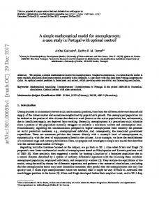
Although there exists an urgent need for conducting more experimental tests on stepped hulls, some researchers have tried to modify well-known Savitsky (1964) method for stepped hulls. Svahn (2009) used presented formulas by Savitsky and Morabito (2010) and extended Savitsky’s (1964) method using wake theory for performance prediction of one stepped hull. Kaidy (2013) also developed a computer program to estimate trim and resistance of one stepped planning hulls. Danielsson and Stromquist (2012) tried to develop Svahn’s model for two stepped hulls. However, they failed in implementation of wake theory of Savitsky and Morabito (2010) for two stepped hull because of range of applicability and other issues. Therefore, they assumed that flow separates from step and reattaches to after-body portion of hull by a linear trend. This assumption was reasonable in very high-speed situation. However, Danielsson and Stromquist (2012) had some difficulties in definition of wetted length and Reynolds numbers. Moreover, there was a lack of complete and accurate validation for their model. In the current article, an attempt has been made to develop a novel mathematical model based on Danielsson and Stromquist (2012) studies. As mentioned in literature survey, there has been no direct measurement or empirical formula for wake profile beneath the two stepped hulls. Therefore, some researchers such as Danielsson and Stromquist (2012), based on their observations, have stated that linear wake profile may be a good estimation for flow separation from steps. Therefore the present study attempts to implement this suggestion. Simple relations from existing literature study have also been implemented in a sequential manner to provide a robust computational algorithm for performance prediction of two stepped hulls with transverse steps. Moreover, an extensive set of validation have been performed by using various towing tank test data acquired in previous studies and a detailed discussion on the results have been presented. 2.�Problem Definition In order to achieve a very high-speed at sea is implementation of various tools for total drag reduction. Removal of some part of hull’s bottom leads to flow separation and consequently, reduction of wetted area. In this regards, naval architects try to design planing hulls using various transverse discontinuity in the bottom which are known as step. Generally, three different forms of stepped hulls may be considered in a planing hull identified as transverse step, step pointed aft and re-entrant V step (Figure 1). In the present paper, transverse step has been implemented. In addition to step geometry, step height and longitudinal position of step are also important factors which influence the wetted area. Wetted area of each portion of two stepped hull may be different. Generally, a two stepped hull can be considered as three tandem planing surfaces which have their own planing characteristics such as wetted length, wetted surface, local trim angle, local deadrise angle, Reynolds number, Froude number etc. Therefore, it is vital to consider each planing surface, separately. However, to compute planing characteristics of each individual planing surface, development of an appropriate model for prediction of flow separation from each step is essential. Unfortunately, there is no appropriate wake model as yet which can be used for two stepped hulls. In the present study, it is assumed that flow separates from steps and reattaches to after-body portion by a linear trend. Consequently, various conditions can come into play on planing surfaces which are shown in Figure 2. Various wetted surface have been depicted in Figure 2 and described as follows: a-� Chine wetting condition for fore-body portion of hull b- Chine drying situation of fore-body portion of hull c- Chine drying situation of middle-body portion of hull d-� Chine drying situation of aft-body portion of hull e-� Chine wetting condition for middle-body portion of hull f-� Chine wetting condition for aft-body portion of hull Transverse step
Pointed Aft Step
Re-entered Vee Step
� Fig. 1. Different forms of step.
ICSOS2016
581
a b c d e f g
� Fig. 2. Various possible wetting conditions for planing surfaces.
Various combinations of depicted situations (a to f) in Figure 2 can occur at different Froude numbers. Generally, because of dividing two stepped hull as three tandem planing surfaces, hydrodynamic lift also distributes in three different parts. To recognize how lift distributes over hull, equilibrium equations which are presented in the next section need to be solved. 3.�Mathematical Model
In this section, equations of motions related to two stepped planing hulls have been derived. For this purpose, two stepped hull is divided to fore-body, middle-body and after-body parts and various planing characteristics of each individual planing surface are calculated. Moreover, it is assumed that each planing body is related to next planing surface by a linear wake profile. Complete features of mathematical model including motion equations, characteristics of each planing surface and computational procedure are presented in the following subsections. 3.1.�Motion equation in equilibrium condition
To derive equilibrium equations of a stepped planing hull, it is convenient to divide stepped hulls to several planing surfaces. Generally, a stepped hull with n steps can be considered as n+1 planing area with individual planing characteristics (Figure 3). Equations of motion for equilibrium condition have been written as follows: n #1
Heave Direction: � mg #
� !lift * cos(� i
o
# � i ) � Dfrictioni * sin(� o # � i )" $ 0
i $1 n #1
Pitch Direction: � mg * lcg * cos(� o ) #
� !lift * d i
i
� Dfrictioni * Drafti / 2 " $ 0
(1)
i $1
2
where m is hull mass (kg), g is gravitational constant (m/s ), lcg is longitudinal position of center of gravity and �o is overall trim angle of planing hull. Moreover, lifti, Dfrictioni, �i, di and Draft are hydrodynamic lift, frictional resistance, local trim angle, lift arm moment and draft related to i-th planing surface respectively. It should be noted that origin of coordinate system is located on lower edge of the transom and pitch moments are calculated relative to this point. In the next part, the computational details of planing characteristics have been presented.
ICSOS2016
582
mg
�1 T
�3 Dfriction3
�2 Dfriction2 Lift2
Dfriction1 Lift1
Lift3
� Fig. 3. Forces acting on each planing surface in equilibrium condition.
3.2.�Planing equations and computation procedure
To obtain various forces and planing parameters in Equation 1, two assumptions have been made which are as follows: 1. Linear Wake Profile (LWP): As mentioned in Danielsson and Stromquist, 2012, there is no reliable formula for fluid flow separation from steps, especially in the case of two stepped hulls. Therefore, because of very high-speed situation of two stepped hulls, linear wake profile may be considered as a reasonable assumption (Danielsson and Stromquist, 2012). 2. Tandem Planing Surfaces (TPS): A planing hull with n steps can be considered as n+1 planing surfaces with individual planing characteristics. These tandem planing surfaces will be connected to each other using LWP assumption. To calculate various planing characteristics of TPS and solve equilibrium equations, well known formulas and method of Savitsky (1964) will be extended to two stepped hulls. However, it must be noted that these relations should be utilized in proper order which are discussed below.
3.2.1.�Planing Characteristics of Fore-body At first, overall wetted length, Lweto , and general trim angle, �o , are guessed (Figure 4). Therefore, it is possible to calculate the wetted length of various body parts as follow,
� Lwet1 ! Lweto � Lstep1 � � Lwet2 ! Lstep1 � Lstep2 � Ldry2 � Lwet ! Lstep � Ldry � 3 2 3
Fore-body Middle-body
(2)
Aft-body
where Lstepj is the distance of steps from transom. To obtain wetted length of middle-body and aft-bodies, we should recognize how the fluid flow separate from steps. Based on LWP assumption, dry length of middle and aft-bodies can be estimated as follow, Hstep2 � � Ldry2 ! tan(� " � ) � o 1 � Hstep 3 � Ldry ! 3 �� tan(� o " � 2 )
Middle-Body
(3)
Aft-Body
where Hstepj is the height of step. It must be noted that the computational procedure is limited to situations where the separation continues across the step. Consequently, spray angles, �i , can be evaluated as follow,
� � * tan(� o ! � i ) � � � 2* tan( �i )
� i " tan �1
for i " 1, 2,3
(4)
where �i is the deadrise angle. Using Equation 4, wetted beam of each body part is obtained as follow,
ICSOS2016
583
Lwo
�2�
�3�
Lw3
Lw2
�1�
Lw1
�
Fig. 4. Wetted area of a stepped planing hull.
bi ! 2* Lweti * tan(� i )
for i ! 1, 2,3
(5)
It must be noted that calculated wetted beam may be larger than chine beam (bi