IEEE TRANSACTIONS ON APPLIED SUPERCONDUCTIVITY, VOL. 15, NO. 2, JUNE 2005
785
Development of a SQUID Readout System for the MiniGRAIL Martin Podt, Luciano Gottardi, Arlette de Waard, Giorgio Frossati, and Jaap Flokstra
Abstract—The MiniGRAIL is one of the three similar spherical gravitational wave detectors that are currently being developed. The detector has a resonant frequency of about 3 kHz and will be operated at 20 mK. The ultimate goal is to use a readout system consisting of six transducers coupled to nearly quantum limited two-stage SQUIDs. The two-stage SQUIDs are based on double relaxation oscillation SQUIDs, which enables a direct voltage readout scheme. We have developed nonintegrated two-stage SQUIDs and experimentally verified the proper operation of the system coupled to a capacitive transducer. Based on the results that were achieved, integrated two-stage SQUIDs were designed. Special attention has been paid to the sensor SQUID, the back action of the SQUID and the feedback scheme that is used for linearizing the SQUID output. Index Terms—Gravitational wave antenna, SQUIDs, superconducting devices.
I. INTRODUCTION
T
HE MiniGRAIL is the first spherical gravitational wave detector that is being developed [1]–[3]. Similar detectors are under construction in São Paulo [4] and in Rome. Recently, the CuAl 6% sphere that is used in the MiniGRAIL was replaced. The new sphere (also CuAl 6%) has a diameter of 68 cm, a mass of 1400 kg, a resonance frequency of 2800 Hz and the operation temperature will be around 20 mK. When excited by a gravitational wave, it is expected to show extremely small . For the readout of the displacements of the order of MiniGRAIL, capacitive and inductive transducers are being developed that are coupled to two-stage SQUID systems based on double relaxation oscillation SQUIDs (DROSs) [5], [6]. In this paper we focus on the design of our new two-stage SQUID systems for the readout of the MiniGRAIL. II. TWO-STAGE SQUID SYSTEMS
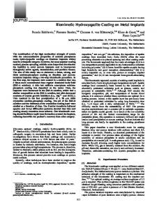
Fig. 1. (a) Scheme of a two-stage SQUID system. The sensor SQUID is . voltage biased using a small bias resistor R
when the SQUID is cooled down to the mK range [7]–[9]. In order to prevent RT preamplifier limitation of the overall system sensitivity, two-stage SQUID systems are required for the readout of MiniGRAIL. The first stage of a two-stage SQUID is a sensor SQUID biased at a constant voltage , see Fig. 1. In this mode, the SQUID acts as a flux-to-current converter. The output current of the SQUID runs through the input coil of a second SQUID. The mutual inductance between the input coil inductance and the second stage SQUID inductance is dimensioned such that the flux gain is larger than unity. Here is the flux coupled into the second stage and is the signal flux applied to the sensor SQUID. Consequently, the output signal of the sensor SQUID is amplified by the second stage and in a well-designed two-stage SQUID system, the sensor SQUID determines the overall system noise.
A. Operation Principle
B. Noise
Generally, a dc SQUID is biased at a constant bias current. In this mode, the SQUID acts as a flux-to-voltage converter but the flux-to-voltage transfer of a standard dc SQUID is only of the order of 100 . This can lead to room temperature (RT) preamplifier limitation of the sensitivity, especially
For an optimized sensor SQUID, i.e. in case the screening parameter of the SQUID , , the flux noise spectral density in the classical limit is given by:
Manuscript received October 5, 2004. This work was supported in part by Stichting Technische Wetenschappen (STW). M. Podt was with the University of Twente, but is currently with Thales Nederland B.V., 7550 GD Hengelo, The Netherlands (e-mail: martin.podt@ nl.thalesgroup.com). L. Gottardi, A. de Waard, and G. Frossati are with the Kamerlingh Onnes Laboratory, Leiden University, 2300 RA Leiden, The Netherlands (e-mail:
[email protected]). J. Flokstra is with the Faculty of Science and Technology, MESA+ Institute for Nanotechnology, University of Twente, 7500 AE Enschede, The Netherlands (e-mail:
[email protected]). Digital Object Identifier 10.1109/TASC.2005.850061
is the critical current of one junction, is the where sensor SQUID inductance, is the Boltzmann constant, is the operation temperature of the SQUID and is the shunt resistance. For example, the sensor SQUIDs that have been developed for the inductive readout of MiniGRAIL have the following parameters: , and . This means that the expected flux noise of these SQUIDs at a temperature of is and the corresponding energy resolution is .
(1)
1051-8223/$20.00 © 2005 IEEE
786
IEEE TRANSACTIONS ON APPLIED SUPERCONDUCTIVITY, VOL. 15, NO. 2, JUNE 2005
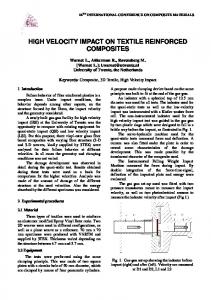
Fig. 2. (a) Energy resolution of a sensor SQUID as a function of the temperature. Micrograph (b) and scheme (c) of the sensor SQUID with cooling fins (grey blocks) added to the shunt resistors.
However, if these SQUIDs would be operated at the same , the flux noise temperature as the sphere, i.e. is expected to decrease to and the energy resolution should reach the quantum limit. The flux-to-voltage transfer of these SQUIDs was , and thus the corresponding output voltage noise at 20 mK is , which is impossible to be measured using a direct voltage readout scheme. By using a two-stage SQUID the flux-to-voltage transfer can be increased by two orders of magnitude, such that the output voltage noise of the two-stage SQUID system can be made larger than the input voltage noise of the RT preamplifier without losing sensitivity. If the operation temperature is sufficiently reduced, it is expected that the intrinsic energy resolution of the two-stage SQUID systems can reach the quantum limit. However, the hot-electron effect can prevent the experimental energy resolution to be (nearly) quantum limited [10]. The bias current that runs through the shunt resistors creates Joule heating. Because of the limited rate at which the electrons in the shunt resistors can transfer energy to the phonons at low temperature, the temperature of the electrons in the shunt resistors can be larger than the temperature of the substrate. The hot-electron effect can form a limitation to the energy resolution of the sensor SQUID and causes the energy resolution to level off at the mK range, as is schematically shown in Fig. 2(a). Hence it is important that the shunt resistors are sufficiently cooled. Therefore, cooling fins were added to the shunt resistors of our new SQUIDs, see Fig. 2(b). The total flux noise of a two-stage SQUID system with direct voltage readout can be expressed as: (2) Here, it is assumed that the noise of the bias resistor can be neglected, which is justified by the fact that generally . is the flux noise of the DROS, is input voltage noise of the RT preamplifier and is the flux-to-voltage transfer of the second stage. Since in our case a double relaxation oscillation SQUID (DROS) is used as the second stage, is so large that the contribution of the RT
preamplifier noise is much smaller than the flux noise of the second stage. For example, the DROSs that we are currently using as the second stages have experimental flux noise levels at 4.2 K. The flux-to-voltage transfers of of these SQUIDs are of the order of and the input voltage noise of our homemade readout electronics is . Hence, the noise of the preamplifier corresponds to a flux noise (referred to the DROS) of . The maximum flux gain of , thus the total contribution our two-stage SQUID is of the DROS and the electronics referred to the sensor SQUID can be calculated to be 0.17 at 4.2 K. This is almost one order of magnitude smaller than the intrinsic flux noise of the sensor SQUID . This means that the experimental flux noise of a two-stage SQUID system based on a DROS can be considered as the intrinsic flux noise of the sensor SQUID. If the DROS is cooled below 4.2 K, the noise of the DROS decreases and the flux-to-voltage transfer will increase. Consequently, it should be possible to measure the intrinsic flux noise of the sensor SQUID at the mK. III. SENSOR SQUIDS FOR MINIGRAIL For the readout of MiniGRAIL, both inductive and capacitive transducers are being developed [6]. For the inductive transducers that are currently under development, the required input coil inductance of the sensor SQUID is of the order of 150 nH. The capacitive transducers require much large input coils, i.e. . Previously we have successfully demonstrated the operation of uncoupled integrated two-stage SQUID systems at a temperature of 4.2 K [7]–[9]. The SQUID inducand the input tance of the sensor SQUID was . The energy resolution of coil inductance was these devices at 4.2 K was measured to be and the 3 dB bandwidth in closed loop was 2.5 MHz. For the MiniGRAIL, the resonant frequency of the detector is 2.8 kHz, such that a large bandwidth is in principle not required. This also enables the possibility to use nonintegrated two-stage SQUID systems consisting of separate chips for the sensor SQUIDs and the second stage SQUIDs. This allows a higher design flexibility and makes testing of different sensor SQUID concepts easier.
PODT et al.: DEVELOPMENT OF A SQUID READOUT SYSTEM FOR THE MiniGRAIL
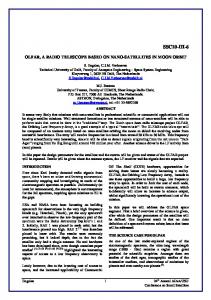
Fig. 3. Micrograph (a), scheme (b) and (c) I
0V
787
characteristics of a sensor SQUID with integrated input transformer.
A. Instabilities Parasitic coupling in the two-stage SQUID systems that are used for the readout of the resonating transducers can drive the resonator into instability. This parasitic coupling can have both a capacitive and an inductive origin. Parasitic coupling between the SQUID and the input coil can drive a current from the output of the SQUID through the resonator and in this way the resonance can be pumped. Instabilities can also arise from the inductive coupling between the feedback coil and the input coil. Hence it is important that both the capacitive and the inductive parasitic coupling in the sensor SQUID are reduced as much as possible. B. Design of New Sensor SQUIDs In order to reduce the capacitive coupling between SQUID and the input coil, we have developed sensor SQUIDs with integrated input transformers, see Fig. 3. These SQUIDs were developed for the capacitive transducers and the input inductance was measured to be . A main advantage of the input transformer is that the effects of resonances in the input coil are drastically reduced, which results in current vs. voltage characteristics without deformations [11], see Fig. 3(c). Based on the experimental results achieved using the sensor SQUID with integrated input transformer, a fully optimized new design was HYPRES [12] design made in accordance with the 100 rules, see Fig. 4. The designed input inductance is and the effective mutual inductance with the SQUID is calcu. The SQUID inductance was thelated as and the theoretical oretically estimated to be energy resolution of this SQUID at is . The input transformer and the SQUID washer are connected via coaxial strip lines to reduce the parasitic inductance in the transformer as much as possible. In order to prevent coupling between the feedback coil and the input coil, SQUID systems with a symmetric design have been developed [13], [14]. These systems use either four-hole washers or four single-hole washers that are connected in a symmetric configuration in order to provide separate secondaries for the input and the feedback circuits. Although the parasitic coupling between input and feedback circuits can be prevented in this way, the parasitic capacitance between the
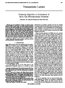
Fig. 4. (a) Schematic overview of the sensor SQUID with integrated input transformer. (b) Layout of the new sensor SQUID with integrated input transformer for readout of the capacitive transducers of MiniGRAIL.
SQUID and the input coil is large, since these SQUID systems require a large number of turns for the input circuitry on top of the SQUID washers. However, instabilities due to parasitic inductive coupling can be prevented by using a cold damping network [11], [15]. We have developed sensor SQUIDs with a symmetric layout and with parameters that are optimized for the capacitive transducers of MiniGRAIL based on the 30 HYPRES process. For the inductive transducers we have designed integrated two-stage SQUID systems in accordance with the 100 HYPRES design rules. The theoretical white energy resolution at 4.2 K, i.e. the of the two-stage SQUID system is SQUIDs are similar to the ones that are used in the SQUIDs with input transformers. The input coil inductance of these SQUIDs ranges from 140 to 170 nH. The wideband version of the integrated two-stage SQUID systems has an intrinsic bandwidth of 11 MHz. This is much larger than the required bandwidth
788
IEEE TRANSACTIONS ON APPLIED SUPERCONDUCTIVITY, VOL. 15, NO. 2, JUNE 2005
for MiniGRAIL but this enables these SQUIDs to be used for high-speed applications, such as the readout of particle detectors. The expected flux-to-voltage transfer of the DROS that is and the maxused as the second stage is imum flux gain between the sensor SQUID and the DROS is . The theoretical voltage modulation depth of the . The two-stage SQUID system is calculated to be theoretical maximum flux-to-voltage transfer of the two-stage . However, SQUID system is based on previous results, we expect that the experimental value will be smaller. IV. CONCLUSION AND DISCUSSION For the readout of the MiniGRAIL, we are developing twostage SQUID systems based on double relaxation oscillation SQUIDs (DROSs) as the second stage. Previous experiments have shown that a DROS allows a direct voltage readout scheme without reducing the overall system sensitivity. The current research concentrates on the development of new sensor SQUIDs that can be operated of the mK range and that have an energy resolution near the quantum limit. In order to prevent limitation to the energy resolution due to the hot-electron effect, we have added cooling fins to the sensor SQUIDs. Several designs have been made for the sensor SQUIDs that can be used to prevent instabilities due to parasitic capacitive and inductive coupling. Experiments on these new SQUIDs will be carried out in the near future. Our next step is to integrate all separate elements on one single chip. This chip will contain a symmetric sensor SQUID with a DROS as the second stage and a transformer connected to the input coil of the sensor SQUID. This allows the numbers of turns on top of the SQUID washer to be reduced drastically such that the capacitance between the SQUID and the input coil can be greatly reduced compared to the design in [13], [14].
REFERENCES [1] MiniGRAIL homepage [Online]. Available: http://www.minigrail.nl [2] A. de Waard, L. Gottardi, and G. Frossati, “MiniGRAIL progress report 2001: the first cooldown,” Class. Quantum Grav., vol. 19, pp. 1935–1941, 2002. [3] A. de Waard, L. Gottardi, J. van Houwelingen, A. Shumack, and G. Frossati, “MiniGRAIL, the first spherical detector,” Class. Quantum Grav., vol. 20, pp. S143–S151, 2003. [4] O. D. Aguiar, L. A. Andrade, J. J. Barroso, L. Camargo Filho, L. A. Carneiro, and C. S. Castro et al., “The Brazilian spherical detector: progress and plans,” Class. Quantum Grav., vol. 21, pp. S457–S463, 2004. [5] M. Podt, L. Gottardi, A. de Waard, G. Frossati, and J. Flokstra, “A spherical gravitational wave detector readout by nearly quantum limited SQUIDs,” Supercond. Sci. Technol., vol. 16, pp. 1531–1535, 2003. [6] L. Gottardi, M. Podt, M. Bassan, J. Flokstra, A. Karbalai-Sadegh, and Y. Minenkov et al., “Two-stage SQUID systems and transducers development for MiniGRAIL,” Class. Quantum Grav., vol. 21, pp. S1191–S1196, 2004. [7] M. Podt, M. J. van Duuren, A. W. Hamster, J. Flokstra, and H. Rogalla, “Two-stage amplifier based on a double relaxation oscillation superconducting quantum interference device,” Appl. Phys. Lett., vol. 75, pp. 2316–2318, 1999. [8] M. Podt, J. Flokstra, and H. Rogalla, “Low-noise SQUIDs with large transfer: Two-stage SQUIDs based on DROSs,” Physica C, vol. 372–376, pp. 225–228, 2002. [9] M. Podt, “Wideband Low-Noise Integrated SQUID Systems,” Ph.D. dissertation, Faculty of Science and Technology, University of Twente, Enschede, The Netherlands, 2003. [10] F. C. Wellstood, C. Urbina, and J. Clarke, “Hot-electron limitation to the sensitivity of the dc superconducting quantum interference device,” Appl. Phys. Lett., vol. 54, pp. 2599–2601, 1989. [11] R. Ackermann, Y. Benzaim, G. Frossati, L. Gottardi, A. Karbalai-Sadegh, and W. Reincke et al., “Present Status of MiniGRAIL,” , to be published. [12] HYPRES, Inc., 175 Clearbrook Rd., Elmsford, NY 10523 [Online]. Available: http://www.hypres.com [13] M. B. Simmonds, “High symmetric dc squid system,” US Patent no. 5 053 834, 1991. [14] R. H. Cantor, “Low-noise symmetric dc squid system having two pairs of washer coils and a pair of josephson junctions connected in series,” US Patent no. 5 656 936, 1997. [15] A. Vinante, M. Bonaldi, P. Falferi, M. Cerdonio, R. Mezzena, and G. A. Prodi et al., “Stabilization and optimization of a two-stage dc SQUID coupled to a high Q resonator,” Physica C, vol. 368, pp. 176–180, 2002.