Jeff Haberl, Charles Culp, Bahman Yazdani. Energy Systems Laboratory ..... Cordes, Robert Stackhouse, Stephen O'Neal, Matt. Moss, Megan Bednarz, Sean ...
Eleventh International IBPSA Conference Glasgow, Scotland July 27-30, 2009
DEVELOPMENT OF A WEB-BASED, CODE-COMPLIANT 2001 IECC RESIDENTIAL SIMULATOR FOR TEXAS Jeff Haberl, Charles Culp, Bahman Yazdani Energy Systems Laboratory, Texas Engineering Experiment Station College Station, Texas 77843-3581 http://esl.tamu.edu
ABSTRACT This paper describes the development of a web-based, code-compliant 2001 IECC1 residential simulation for Texas. Included in the paper is a description of the software and database platform used in the web application and how this software is attached to the DOE-2 legacy software running on a cluster of servers attached to the web. Additional information is included about how a residence is dynamically updated by the web-page, using macro commands and a flexible yet fixed-schematic input file. This tool is currently in use by builders in Texas to check code compliance of new residential construction. It also calculates NOx, SOx and CO2 emissions reductions from the energy savings of the proposed house for the electric utility associated with the user using the data from the Emissions and Generation Resource Integrated Database (eGRID) provided by U.S. Environmental Protection Agency.
BACKGROUND Residential energy standards provide a minimum standard for energy-efficient homes and thus help reduce emissions from electricity generation. The Energy Systems Laboratory (ESL) has developed several web-based, energy efficiency and emissions reduction calculators. The International Code Compliance Calculator (IC3)2 is provided for use by builders in Texas, home energy raters, and code officials to benchmark the estimated energy performance of new construction single family homes in Texas. IC3 was built to be very easy to use yet it performs hourly simulations of the user’s house compared to a 2001 IECC code-compliant house for the specific location in Texas. It also calculates how much air pollution has been reduced through the home’s energy efficiency3. This paper presents the
methodology used in the IC3 for calculating the energy usage for the proposed residential house compared to the house meeting the minimum requirement of 2001 IECC.
METHODOLOGY The simulation models, created with the DOE-2.1e simulation program (LBNL, 1993a, 1993b), are linked to a web-based graphical user interface (IC3) or can be used in the DOE-2 Desktop Processor (DDP) to calculate the energy use from the code-compliant house and a proposed house. To calculate the impact on the reduction in air pollution the USEPA’s eGRID4 is used to convert the energy savings to NOx emissions reduction5. In the web-based interface, one user house is allowed to be input at a time in the current version of IC3. By contrast, in the DDP, which is used internally at the ESL for analysis, multiple simulation runs can be submitted by an input spreadsheet at the same time which is very convenient for the users, developers, and for testing purposes.
OVERVIEW In a performance analysis using the 2001 IECC, two simulations are needed for the assessment of energy savings in a code-compliance calculator. One is the code-compliant run based on the minimum construction requirement of the 2001 IECC standard design and the second run is the simulation of the proposed design with the user input. The codecompliant simulation represents a simulation of the same user house with specific characteristics made compliant with the 2001 IECC. The comparison of the simulated annual energy use of the user’s proposed design to the code-compliant simulation allows the user
1 In this paper 2001 IECC is used to designate the 2000 IECC including the 2001 Supplement (IECC, 2000, 2001) and 2006 NAECA. 2 IC3 (ver. 3.2) is available at http://ic3.tamu.edu/, (IC3, 2007). 3 The earliest version of the code-compliant calculator was called ecalc, “ecalc.tamu.edu”, which was developed for the State of Texas using funding from the U.S.E.P.A. (ecalc, 2005). A significant number of features of IC3 were first demonstrated in the Texas Climate Vision project (TCV), a joint
project with the City of Austin, funded by the Texas State Energy Conservation Office with funding by the USDOE (Morgan, 2007; TCV, 2008). 4 eGRID, is the EPA’s Emissions and Generation Resource Integrated Database (Version 2). This publicly available database can be found at www.epa.gov/airmarkets/egrid/. The information in this table is from a special edition of the eGRID database, provided by Art Diem at the USEPA for the TCEQ for use with Senate Bill 5 (EPA, 2002). 5 NOx emissions from natural gas used on-site are calculated with data from the EPA’s AP-42 database
- 851 -
to see if their house is more efficient than a codecompliant house. The complete process flow using two different input interfaces is depicted in Figure 1. In the simulation the 2001 IECC code characteristics for the single family residences are based on the minimum requirements according to the climate zone where the user’s county is located. For a performance simulation, exterior wall and glazing U-factors are found in Tables 402.1.1(1) and 402.1.1(2) of Chapter 4 of the 2001 IECC. The remaining envelope characteristics and minimum HVAC equipment efficiency requirements are acquired from the prescriptive tables in Chapter 5. For example, if the user chooses Harris County6 then the code house characteristics will be as shown in Table 1. Typical Meteorological Year 2 (TMY2) data files are used in the simulations. Currently weather files are assigned according to the counties chosen by the user. For example, for Harris County, TMY2 weather data from Houston’s Bush Intercontinental Airport is used.
SYSTEMS. The LOADS parameters are then further divided into building, construction, space, and shading parameter subsets (Liu et al., 2008). Using DDP
Using IC3 User input from Web Interface
User input from DDP Spreadsheet
IC3 Calculation Engine
DDP Calculation Engine
Code-compliant House - Include files
User House - Include files (parameters.txt,
(parameters.txt, county.txt, shades.txt)
county.txt, shades.txt)
DOE-2 Input Files
Weather File (TMY2)
DOE-2 Output Files (BEPS)
Annual & OSD Emissions Calculations
% Above Code (IECC 2000 with 2001 Supplement)
Certificates Writer
PCA Proportioning Table eGRID Emissions Reductions
Certificate
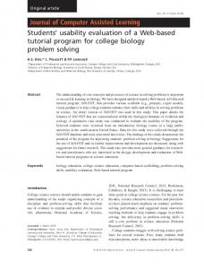
The two sets of simulation inputs are then processed using DOE-2 to determine the energy consumption of the building (Figure 1). For 2001 IECC code compliance, the values of interest from the DOE-2 are the annual electricity and gas consumption in kWh and therms, which are then converted to Btu and summed for a total annual energy use. The total annual energy use from the user’s run are then compared with the results from the code compliant simulation to determine if the house is more or less energy efficient than the code-compliant house7. Simulation Input File The simulation input files consist of 4 basic files, one DOE-2 “input” file and three DOE-2 “include” files (i.e., county.txt, shades.txt, and parameters.txt). The DOE-2 input file contains a “flexible” simulation model for the single family residence with pre-defined parameters. Three include files are generated by a preprocessor or calculation engine based on the user input, as shown in Figure 1. County.txt includes information such as heating degree days, latitude, longitude, time-zone, altitude and infiltration which is determined from the county in which the house is located. Shades.txt provides interior shading schedules for the simulation input file. Parameters.txt is generated from the user’s web inputs and default settings. The parameters are divided into two major categories as defined by the DOE-2 program; LOADS and
Figure 1 Single Family Analysis Flowchart The building parameters are used to define the location, orientation, and the basic dimensions and layout of the building. The current simulation model has the provision of either one or two stories with a crawlspace or a slab on grade. The layering of the wall is decided based on the requirement in Section 402.1.1 of Chapter 4 of the 2001 IECC. Framing factors are determined for walls, ceilings, and floors according to the recommended values by ASHRAE research project RP-904 (Carpenter et al., 2003)8. The construction parameters for the material properties and U-values for the different components include the glazing properties and the window-to-wall ratio. The user also has the option of changing the window areas for the different orientations. For the code run, the window area is fixed at 18% of the conditioned floor area and is divided equally between four cardinal directions, and by floor if needed. An annual average air change per hour method is used as the infiltration method in the simulation, which is determined using the normalized leakage multiplied by the weather factor. The weather factor is determined in accordance with the weather factors given by ASHRAE Standard
6
8 In addition an internal “switch” is available for using different methods of calculating thermal mass with the DOE-2 program. These include a “quick” mode (i.e., pre-calculated ASHRAE weighting factors) and a “thermal mass” mode (i.e., DOE-2’s custom weighting factors). The current mode uses the thermal mass construction for the current version.
Harris County is in the Houston metropolitan area. The savings values are then further processed by the routine that uses eGRID to calculate the annual and Ozone Season Day (OSD) NOx emissions reduction number in lbs of NOx for the power plant that supplied the electricity use to the county in which the house was built. 7
- 852 -
136-1993 (ASHRAE, 136, 1993 and IECC, 2000, 2001), as appropriate for the assigned weather station. Table 1 Code Building Characteristics for Harris County County
Building Characteristics
Harris
2001 IECC
Glazing Properties U-Factor 0.47
Btu/hr-sq.ft-F
2.67
W/(m .K)
2
Minimum HVAC Efficiencies
Envelope Properties
SHGC 0.4
Wall R-Value 13
Hr-sq.ft-F/Btu
2.29
m .K/W
2
Roof R- Value 30
Hr-sq.ft-F/Btu
5.28
m .K/W
2
Cooling Heating SEER (AFUE) 13
0.78
For simulating residential buildings, according to the 2001 IECC, internal heat gains are fixed at 3,000 Btu/hr (879 W) for a single-family dwelling, which limits the user’s ability to change the lighting, occupancy and equipment gains. The space parameters are therefore fixed at no occupants. The same number of bedrooms is input by the user for the code run. The number of bedrooms is used to calculate the daily domestic hot water consumption, which in turn is used to size the domestic water heater according to Section 420.1.3.7 of the 2001 IECC. An Energy Factor (EF) is used for the domestic water heating system efficiency according to Table 504.2 of Chapter 5 of the 2001 IECC for the code run. The system parameters include the type of systems, the system capacity and the efficiencies of the system selected. The user can choose from three kinds of systems: 1) gas heating, gas DHW and electric cooling, 2) electric resistance heating, electric DHW and electric cooling, and 3) electric heat pump heating, electric DHW and electric cooling. For gas consuming households no pilot light is assumed for both the user and code house since the energy use of the pilot light is included in the EF of a the DHW system. No pilot light is assumed for the gas-fired heating system9. Currently, three system sizing choices are available in the DDP. The heating and cooling system can be sized by DOE-2 according to the loads calculated by DOE-2, or by Manual J spreadsheet linked to the DDP, or by a rule of thumb10 which uses 500 ft2/ton (13.2 m2/kW). A value of 360 CFM/ton (48.26 L/s/kW) is used for heating and cooling coil airflow capacity. The user can define the system efficiencies according to the system type that is selected. For the code simulations, the HVAC efficiencies conform to the values in Table 1. IC3 also included improved coefficients to properly account for the part-load performance of residential air conditioning systems developed the Florida Solar
Energy Center (Henderson et al., 2000). For simulating a heat pump, the heating EIR (Energy Input Ratio) and cooling EIR values are from an evaluation of the data for several thousand air conditioners and heat pumps listed in the California Energy Commission appliance database (Fairey et al., 2004). The analysis of the heat loss/gain and air leakage in the supply/return in the ductwork in the unconditioned space (attic) is uses a specially developed duct model based on ASHRAE Standard 152-2004 (Kim, 2006)11. Running the Simulations There are two tools to run the simulations. One is through the IC3 web interface and the other is through the batch mode DOE-2 Desktop Processor. Those two independent tools allow for continuous cross-checking.
Figure 2 DOE-2 Desktop Processor (DDP) and Example Input Spreadsheet Figure 2 shows the DOE-2 Desktop Processor screen and the DDP spreadsheet which allows for 1,000s of simulation instructions to be loaded into one file for testing purposes. Besides the parameters shown in the web-interface, more parameters can be changed in this DDP tool for comparing a user house and the house meeting minimum code requirement. Additional views of the web-based screens and certificate are included in the appendix. Handling the Workflow from the Web Interface In IC3 users log in and either enter a new home (called a project) or select an existing project for further
9
According to a survey of gas-fired furnace manufacturers pilot lights were replaced with electronic ignition systems in gas-fired heating systems to meet the national AFUE requirements referenced in the 2001 IECC. 10 In the current IC3 web-based software, the 500 ft2/ton (13.2 m2/kW) is used for sizing the system.
11 Accuracy testing of the simulation is currently underway using the RESNet certification process, which includes BESTEST procedures, as well as side-byside comparisons with other available code-compliant simulations (private and public).
- 853 -
edition12. If they have not yet signed up, the user may create an account by filling in their email address and their password. If the current project is at or above code, then the user will receive a certificate (as an Adobe PDF file) suitable for printing, saving or emailing. If the home is below code, then the system will show the user where they may have missed an input and/or warns the user that the home is below code. The IC3 Software consists of many logical packages or layers as follows: Web Software; Database; and Calculation Engine. Each of these layers is further divided as described below. An overview of this architecture is provided in Figure 3. The fully assembled software is deployed to two locations on the Test Tier and two on the Production Tier as described in Figure 4.
should be able to handle over 50 concurrent users without experiencing a delay15. Views: This is the part of the program that “runs” in a browser. These are built dynamically using HTML and CSS technology, along with JavaScript where necessary. The Views provides placeholders for the actual controls (i.e., fields, buttons, and menus), and applies a “skin” to them so they appear homogeneous with the rest of the site. The software currently supports Microsoft Internet Explorer (IE), versions 5 and 6, and Mozilla FireFox16, versions 2.2 and 3.0. Initial testing indicates that IE version 8 and Google’s Chrome browser work with only minimal visual differences.
The application is written using a foundation of Microsoft .NET v2.013 running on Microsoft IIS v6.014 hosted on a single HP server. Layered on top of the .NET software is a variety of open-sourced frameworks and libraries organized into three groups, including: views, business/domain rules and energy code rules.
Figure 4 IC3 Deployment
Figure 3 IC3 Architecture: a very high-level overview of the major parts of the web-based software The system has been tested using a small cluster of web servers, thus allowing for larger computing loads. Simulated stress testing indicates that the system
12
Business/Domain Rules: This portion of the web system is written in Microsoft C#17 on top of an open source framework. Together, the values are entered from the View and checked to see if values are within range, properly formatted (i.e., insulation values must be numeric, not letters), translated and then recorded to both the User’s values and the Code Compliant version of the User’s values into the database for the CalcEngines to later process.18 Printing of the certificate for homes that pass is also handled at the WebServer. The certificate is created as an Adobe Acrobat™ file for easy storing, printing, and emailing. Emissions reduction are calculated by taking the electrical savings, using an historical power allocation
15
Previous projects are stored in an account in the IC3 database for access by the user after they have logged in. 13 http://www.microsoft.com/net/ 14 http://www.microsoft.com/WindowsServer2003/iis/default.mspx
The system’s capacity was based on the following conservative values: 160,000 new homes in Texas in 2006, a maximum of 2,064 working hours in the year, and five minutes per house, giving 6.5 concurrent users. 16 http://en-us.www.mozilla.com/en-US/ 17 http://msdn2.microsoft.com/en-us/vcsharp/default.aspx 18 See the discussion on polling that follows.
- 854 -
per county19 then allocated through EPA’s eGRID20 emissions database to determine emissions by county for pounds of SOx, NOx, and CO2 per Kilowatt hour of savings21. Database IC3 is data driven, which is to say the development effort is focused on creating “engines” that are as generic as possible and are “fueled” by data. The data is split between reference values, the actual projects, user data and simulation data. Reference Values: These are values stored for use by the User Interface and the Calc Engines that are not usually “hard coded” into the software. Rather, they tend to “persist” either in XML files (if they only need to be loaded once and kept in memory) or in the central SQL Server database (if they are numerous and require a lookup for each project, such as the eGRID data used to calculate emissions reductions). House (Project) Data: This is the data kept for each and every house/duplex/multi-family home. They are called “Projects” by the IC3 software. User information is also stored in the database. The Project data is updated as the simulations are run so they carry calculated values such as their estimated energy values, and emissions. The application protects a builder’s data from all other builders. Simulation (Job) Data: These data are specific to the running of the Calc Engine (see Calculation Engine). They are derived from the Project Data and put into a specific format for the CalcEngines to retrieve process and update. As versions of IC3 require running multiple simulations to arrive at an estimated energy usage, there is a need to store the data during the simulation runs. Storing the data in this way also allows for the system to “Scale Out” by adding CalcEngines when the load requires them. This data is not stored for very long periods of time. Calculation Engine The Calculation Engine (CE) software lives on the CalcServer computers. The CE itself is comprised of several components that perform special functions to
19
The Texas Public Utility Commission published information on how each ERCOT County’s power was allocated according to the Power Control Authorities servicing each County in Texas. This information is used by the ESL in its Annual reports to the TCEQ. 20 http://www.epa.gov/cleanenergy/egrid/index.htm 21 Note that natural gas savings are converted into NOx emissions using the EPA’s emissions factors. EPA AP42 Project, published in 2003, www.epa.gov/ttn/chief/ap42/ap42supp.html. the software uses a specially prepared version of eGrid for annual and Ozone Season Day calculations for the year 2007.
move data from the Jobs Database, to the simulation, and then post the results back to the Project Database. Poller: Each CalcServer runs a query against its target Job database as often as once per second. The timing is controlled by a value in a configuration file hosted on the hosting CalcServer. The system was designed to accommodate additional users and, thus, simulation runs by simply adding CalcServers and their CE’s, which is a way that the system is “self balancing” and “scales out.” When a Job is found (based on the Status field in the Jobs Database), the Poller retrieves the Job data and transfers it to the Simulation Interface. Simulation Interface: This component of the CalcEngine processes the Job Data and prepares it for use by the legacy simulation. It writes out the values into files “consumed” by the custom scripts that are then “fed” into the DOE-2 legacy simulation program. This component is also responsible for retrieving the output of the simulation and passes it back to the Project Database. The Simulation: The legacy simulation used for the thermal analysis is the DOE-2.1e program from the Lawrence Berkeley National Laboratory22. Presently, the scripts take the specific Project variables through a specially formatted parameter file. At this time various business and energy code rules are also found in this layer, future versions will see those rules moved out to Business Layer of the system.
CONCLUSIONS This paper has described the development of a webbased, code-compliant residential simulation for Texas. Included in the paper is a description of the software and database platform used in the web application and how this software is attached to the DOE-2 legacy software running on a cluster of servers attached to the web. Additional information was provided regarding how a residence is dynamically updated by the webpage, using macro commands and a flexible yet fixedschematic input file. This tool is currently in use by builders in Texas to check code compliance of new residential construction.
ACKNOWLEDGMENTS This work was supported by the Texas State Legislature through the Texas Emissions Reduction Plan (TERP, 2001), funding from the U.S.E.P.A. and the U.S.D.O.E. It would not have been possible without significant input from the Senate Bill 5 team, including: Zi Liu, Jaya Mukhopadhyay, Mini Malhotra, Seongchan Kim, Don Gilman, Kyle Marshall, Cynthia
22
- 855 -
LBNL 1993a; 1993b
Montgomery; Katherine McKelvey, Juan CarlosBaltazar, Sherrie Hughes, Larry Degelman, Jason Cordes, Robert Stackhouse, Stephen O'Neal, Matt Moss, Megan Bednarz, Sean Choate, Heeyon Cho, Sean Taylor, Vardhaman Bora, Craig Schraeder, Lance Ballard, and David Claridge.
REFERENCES ASHRAE 136. 1993. A Method of Determining Air Change Rates in Detached Dwellings, American Society of Heating, Refrigerating and AirConditioning Engineers, Inc. Carpenter, S.C. Schumacher, C. 2003. Characterization of Framing Factors for Wood-Framed LowRise Residential Buildings (RP-904), TRANSACTIONS- American Society of Heating, Refrigerating and Air Conditioning Engineers, VOL 109; PART 1, pages 101-108. eCalc. 2005. eCalc, a Web Based Energy Efficiency and Emissions Reduction Calculator, Energy Systems Laboratory, Texas A&M University, http://ecalc.tamu.edu. EPA. 2002. eGRID2002 v2.01, EPA Website and application documentation, http://www.epa.gov/cleanenergy/egrid/index.htm. Fairey, P., Parker, D.S., Wilcox, B., Lombardi, M. 2004. Climate Impacts on Heating Seasonal Performance Factor (HSPF) and Seasonal Energy Efficiency Ratio (SEER) for Air Source Heat Pumps. ASHRAE Transactions, American Society of Heating, Refrigerating and Air Conditioning Engineers, Inc., GA. Henderson, H.I., Parker, D.S., Huang, Y.J. 2000. Improving DOE-2’s RESYS Routine: User Defined Functions to Provide More Accurate Part Load Energy User and Humidity Predictions, Proceedings of 2000 Summer Study on Energy Efficiency in Buildings, Vol. 1, p. 113, American Council for an Energy-Efficient Economy, 1001 Connecticut Avenue, Washington, DC. IC3. 2007. International Code Compliance Calculator, Energy Systems Laboratory, Texas A&M University, http://ic3.tamu.edu. IECC. 2001. 2001 Supplement to the International Codes, International Code Congress, Falls Church, Second printing, March. IECC. 2000. International Energy Conservation Code, International Code Congress, Falls Church, VA, Second printing, January 2001. Kim, S. 2006. An Analysis of International Energy Conservation Code (IECC) Compliant SingleFamily Residential Energy Use, Ph.D. Dissertation, Department of Architecture, Texas A&M University.
LBNL. 1993a. DOE-2.1e BDL Summary, Lawrence Berkeley National Laboratory LBNL, Report No. 349346. LBNL. 1993b. DOE-2.1e Supplement. Lawrence Berkeley National Laboratory LBNL, Report No. 349347. Liu, Z., Mukhopadhyay, J., Malhotra, M., Haberl, J., Gilman, D., Montgomery, C., McKelvey, K., Culp, C., Yazdani, B. 2008. Methodology for Residential Building Energy Simulations Implemented in the International Code Compliance Calculator (IC3), Sixteenth Symposium on Improving Building Systems in Hot and Humid Climates, Energy Systems Laboratory Report No. ESL-HH-08-1202, Dallas, Texas (December). Morgan, R., Gilman, D., Mukhopadhyay, J., Marshall, K., Stackhouse, R., Cordes, J., Liu, Z., Montgomery, C., Haberl, J., Culp, C., Yazdani, B. 2007. Development of a Residential CodeCompliant Calculator for the Texas Climate Vision Project, Proceedings of the 15.5 Symposium on Improving Building Systems in Hot and Humid Climates, San Antonio, TX, December 17-18, 2007. TCV. 2008 Texas Climate Vision, Energy Systems Laboratory, Texas A&M University, http://tcv.tamu.edu. TERP. 2001. Texas Emissions Reduction Plan legislation (SB 5, 77th Leg.).
- 856 -
APPENDIX This appendix contains screen shots of the IC3 program that represent what the user sees during a session on the web.
allows a user to specify any overhang of the second floor over the first. The system will trap geometries that cannot be simulated.
Figure 7 IC3Window Tab The Window tab allows for the building level entry of glazing information, as well as each elevation’s windows. Figure 5 IC3 Address Tab The Builder enters the information on the house (Project) they wish to have rated. The “Project Name” field is unique to each Builder’s account and is specifically for their reference.
Figure 8 IC3 Insulation Tab Ceiling and wall insulation: a new field for external sheathing insulation is being evaluated.
Figure 6 IC3 Floor Tab
Figure 9 IC3 Climate Control Tab
This tab starts the process of entering a house (Project). The system supports houses with one or two floors and allows for different measures for each of the floors, and
Here the Builder is able to enter the details of the home’s mechanical systems. As IC3 is a performance calculator, the positive impact of putting the
- 857 -
Mechanicals in Conditioned Space is given due credit. The water heater can have a large impact on the performance of the home.
Figure 10 IC3 Roof Tab These questions allow the system to capture and model the impact of roof construction. In middle and northern climate zones, Radiant Barriers have a modest impact
due to the increased heating energy required in the winter.
Figure 11 IC3 Horizontal Projection Tab The software calculates the shading provided by overhangs on glazing, but in more northern climates, too much shading can reduce the net positive impact due to increased heating energy in the winter.
Figure 12 IC3 Project Status Tab Above screen provides a recap to the builder of all of the prior sections. Errors are noted and allow for one click to return to the tab needing attention. Several common errors are specifically trapped, and with feedback from the users to ESL, the system will provide additional guidance for the more common failure modes in the future. This report is generated by IC3 if the house meets or exceeds Code. It is presented to the Builder as a PDF file and can be saved, printed, or e-mailed for the code review process. Figure 13 IC3 Energy Compliance Certificate
- 858 -