Development of an Automated Crash-Location System for Iowa AASHTO’s GIS-T, San Diego 1999 Reginald R. Souleyrette and Daniel J. Gieseman Center for Transportation Research and Education Iowa State University To recommend effective crash prevention measures, highway safety analysts require accurate and timely incident location data. To this end, the state of Iowa is engaged in a comprehensive program to improve crash data accuracy and availability. The program is known as the National Model for the Statewide Application of Data Collection and Management Technology to Improve Highway Safety (the National Model). The National Model project is a partnership between FHWA and the state of Iowa to demonstrate the successful integration of technology for the improvement of highway safety. The statewide approach and across the board participation by city, county, state and federal agencies make this project unique. This is a single state’s technology integration experience, hence, the objective of the model is to share experiences so others can avoid Iowa's mistakes and take advantage of Iowa's successes. At the same time, model principals hope to hear back from other states on what is working and what has not worked. The foundation for the National Model is a police reporting software package. The software package includes components for crash reporting, citation writing, operating while intoxicated reporting, commercial vehicle inspections and for arrest/incident reporting. Data gathered through the reporting modules allows for almost immediate information for police administrators, safety engineers and other decision-makers. The software package: § § § § §
provides an open architecture allows royalty-free licenses to other states can be customized to mimic the look and feel of existing systems allows for agency specific functionality will maintain data integrity for statewide reporting
Coordination among the various components of the public safety community emphasizes the need for technology integration. As agencies continue to increase their cooperative efforts to achieve public safety goals, the benefits of sharing common data and eliminating redundant data capture activities become clear. Highway safety activities are usually split among several agencies in state government, requiring participation across state agencies. In Iowa the two statewide partners are the Department of Transportation (DOT) and the Department of Public Safety (DPS). The DOT issues driver licenses, maintains the driver record and crash record databases, provides safety engineering, and is the lead agency for commercial vehicle inspection. The Department of Public Safety deploys the State Patrol, provides the statewide law enforcement
Development of an Automated Crash-Location System for Iowa
Page 1
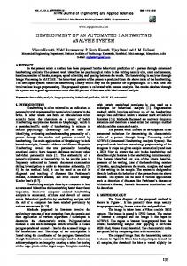
communications system, manages the Governor’s Traffic Safety Bureau and participates in commercial vehicle inspection. Full technology integration requires a close working relationship with local law enforcement agencies (over 60 agencies in Iowa are using electronic data collection). The Judicial Department, the courts and the judges are a key link to complete the data flow circle. Other agencies, including those dealing with disaster management and emergency medical services, are also players. The National Model is Iowa’s way to bring everyone with public safety interests together to further enhance public safety. This paper describes one component of the National Model, the development of an automated crash location process. It illustrates the need for crash location software by describing current location and analysis processes. It also documents the development of the GIS-based crash location approach taken in Iowa. The software is transferable to other states and applications beyond crash location. Crash Analysis in Iowa A brief description of current crash analysis practices in Iowa is included to emphasize the increasing importance of spatial location. Currently, crash data are analyzed using PC-ALAS (Accident Location and Analysis Software). PC-ALAS, a DOS-based software package (see Figure 1), includes many statistical crash analysis and reporting tools. This system is being replaced by a Microsoft Access-based system known as Access-ALAS. Figure 1. PC-ALAS Menu
PC- and Access-ALAS use a node-based referencing system for the location of crashes. This referencing system requires the user to identify 8-digit reference nodes from paper or CAD
Development of an Automated Crash-Location System for Iowa
Page 2
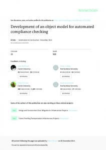
maps (Figure 2). Recently, the statistical and reporting tools of PC-ALAS have been integrated with GIS, in part to eliminate the cumbersome node identification process.1 Figure 2. Example PC-ALAS Node Map
GIS-ALAS uses spatial database query tools to locate and analyze historical crash information. The system permits effective display of crash information (see figure 3). As the historical crash data are referenced only to nodes, GIS-ALAS must convert node references to projected coordinates using straight-line interpolation. This interpolation results in some error for curved roadway segments, and is being replaced by direct capture of coordinates by the automated crash location system.
1. Souleyrette, R., Strauss, T., Pawlovich, M., and Estochen, B.,"GIS ALAS, The Integration and Analysis of Highway Crash Data in a GIS Environment," Geographic Information Systems for Transportation Symposium, American Association of State Highway and Transportation Officials, Salt Lake City, Utah, April 20-22, 1998, pp. 411-428.
Development of an Automated Crash-Location System for Iowa
Page 3
Figure 3. GIS-ALAS Display
Current Location Process Figure 4 illustrates data flow in the current node-based location referencing process. In this process, literal descriptions provided by responding officers or drivers are translated into the appropriate node reference. Clearly, this can be a time consuming and error prone process. Figure 4. Current Crash Location Data Flow PCALAS Paper Officer Report
Bottleneck Central Office Location Processing of Literal Description
Paper Driver Report
Access ALAS
ALAS
Link / Node to XY GISALAS
Development of an Automated Crash-Location System for Iowa
Page 4
With the deployment of the police reporting software package, the DOT is taking steps to eliminate the data processing bottleneck. Data collected by the new software package can flow electronically from officer to DOT headquarters; thus eliminating the need for manual entry of paper based crash data. The Center for Transportation Research and Education has developed an automated crash location system to improve the accuracy and timeliness of obtaining crash locations. This tool is to be integrated into the police reporting software package. Using the system to collect location information eliminates the location bottleneck for records processed using the new software. Figure 5 shows the proposed flow of data after implementation of the electronic data collection tools (note that not all records will be processed by the police reporting software package, initially). Figure 5. Revised Crash Location Process Paper Officer Report
Local Data Analysis
Police reporting software package (local office)
XY to Link / Node Translator
Paper Driver Report
Police reporting software package (mobile)
PC-ALAS
Access ALAS
Police reporting software package (central office/enterprise)
ALAS GIS-ALAS
Automated Crash Location Process A GIS-based application was chosen as the best alternative to improve the accuracy and timeliness of crash location. An oversight committee consisting of local and state officials specified the initial project requirements. The initial recommendations are listed below: • • • • • •
User friendly software interface. Ability to locate locations quickly and accurately on a map. Software is inexpensive/free. Software utilizes data that are readily available and accurate. Software can be integrated with police reporting software package. Software databases are small enough to deploy on portable computers.
Development of an Automated Crash-Location System for Iowa
Page 5
Given the spatial nature of any location process, it was decided that GIS mapping software should be used for application development. Considering the importance of a user-friendly software interface, ability for customization was selected as a key requirement of the GIS software. After implementation (distribution) costs were evaluated, ESRI’s MapObjects software was chosen as the development platform, as applications of the package may be freely distributed. GPS or GIS? It is well known that GPS can directly provide map coordinates. However, it may be impractical to place a GPS receiver in the precise crash location (e.g. due to traffic or terrain constraints). Furthermore, due to inaccuracies in GPS positioning, limited availability of signal in certain areas (urban canyons, tree cover), and varying base map scales and accuracy, GPS cannot always provide crash coordinates that are accurate relative to the base map. Therefore, the automated location system does not rely on GPS for positioning. However, GPS can be used in conjunction with the system to set an appropriate initial map extent, thereby saving valuable onsite processing time. For example, an officer can manually enter GPS coordinate data taken from a handheld GPS unit, or the software can directly read National Marine Electronic Association (NMEA-183) sentences via a GPS receiver serial link. While GPS may provide a more precise location than relatively inaccurate base mapping, it is important to provide the ability to assign key link attribute information from the base mapping to the crash report. In order to accomplish this linkage, a crash location must be accurate relative to the base map. By using relative referencing rather than GPS coordinates, when base map accuracy is later improved, crash locations can be easily adjusted to enhanced cartography. Graphical User Interface The graphical user interface for the automated location system (Figure 6) was designed with ease-of-use as a primary objective. Police officers were not expected to learn complicated GIS software, along with technically detailed digital mapping techniques or procedures. With this in mind, only six buttons drive the interface of the location tool.
Development of an Automated Crash-Location System for Iowa
Page 6
Figure 6. User Interface for Automated Location System User Interface Menu
Main Map Window
Map Coordinate Information
Five of the six buttons provide functionality for manipulating the map. The sixth button is used to access crash locating functions. The buttons are shown in Figure 7. These buttons are the minimum necessary for an officer to use in order to identify and locate a crash scene. Figure 7. Automated Location System Top-level GUI Previous View View Entire Map
Pan Map Zoom In/Out
Crash Locate Tool
Location Specification Tools Initial officer feedback from alpha testing indicated that the most difficult portion of the crash location process is narrowing the broad scale of the map to a specific location. To alleviate this problem, several tools were developed to help an officer narrow the extent of the map roughly to the crash area (Figure 8).
Development of an Automated Crash-Location System for Iowa
Page 7
Figure 8. Location Finder Tools
Coordinate
Milepost
City
County
Intersection
These ‘Finder’ tools provide the user with a variety of applications for locating specific map features. The user can locate map entries based on the following search criteria: • • • • •
X/Y map coordinates Route/Milepost City name County name Intersection
These tools are also designed with ease-of-use in mind. Users need not have any experience with any of the underlying database tables, or know any query language or spatial operators. Most queries are executed instantly, with the exception being the ‘Intersection Finder’ tool. This tool performs a spatial select on the fly, and therefore requires a small amount (approximately 30 seconds) of processing on a Pentium 120 laptop. This query time varies based upon the geographic extent of the currently defined service area (usually a county).
Using the Crash Location System A user indicates a crash location by using the map manipulation tools or location finders to zoom into a particular area of the map. Once the specific location is found, the user clicks on the map where the crash occurred. Feedback about the selected location is then given to the officer. Figure 9 shows the crash location options menu and two screenshots of the Location Data Display. After a crash is located, the Location Data Display shows an officer a small diagram of the crash. If desired, the officer may view additional data by expanding the Location Data Display. Included in the additional data is information about any aliases that the roadway is called and coordinate information for the crash location point. This information is given for each map segment adjoining the crash location.
Development of an Automated Crash-Location System for Iowa
Page 8
Figure 9. Locating a Crash
As a result of feedback from officer testing, additional tools are provided allowing distance measurement, and the ability to ‘snap’ the mouse pointer to the precise location of an intersection. These tools are visible on the crash location menu in the above figure.
Data Communications Protocol Once a crash location is identified and verified by an officer, the system passes data to its client applications using a communications protocol. This protocol establishes a common format from which client applications can read and store data passed from the system. These data are output in the form of a fixed-width text string. Included in the string are: • • • • •
Crash location coordinates. Crash location literal description. Officer comments concerning the map data (if any). Unique database identifiers for each roadway segment adjoining a crash location. Other database attributes as needed.
Client applications can parse the output text, and store only relevant information. In this manner, any or all of the data from the system can be stored, thereby providing a high degree of flexibility to client applications.
Development of an Automated Crash-Location System for Iowa
Page 9
System Deployment The automated crash location system will initially be deployed as a component of the police reporting software package. The application is compiled as a DLL, which can be integrated into any Microsoft COM based OLE compliant software application using any OLE development environment (Visual Basic, Power Builder, Visual C++, etc.). The client/server architecture of the software enables any OLE compliant application to integrate the DLL in order to gather spatial coordinate information. This allows the expansion of the system for collecting location data of other incidents such as traffic citations, arsons, murders, domestic disputes, etc. The location tool can also be expanded to include additional map and data layers, with a minimum of user effort. Geographic area is configured upon initial installation, and can be reconfigured on the fly. While the software can use statewide databases, it is generally preferable to narrow the geographic area, in the interest of improving the time necessary for executing queries and redrawing the map. The system is also designed to provide additional functions to enable rapid and easy setup of any county or group of counties. The Geography Configuration Interface (Figure 10) enables the user to graphically select the geographic region or service area. Databases are then created as subsets of the statewide data included with installation files. These statewide databases are stored on a CD or network location. A simple point-and-click process creates the necessary files. Figure 10. Geography Configuration Interface
Development of an Automated Crash-Location System for Iowa
Page 10
System Maintenance Maintenance falls into two categories: source-code maintenance and database maintenance. As the need arises, source-code changes can be made to adapt to new user needs or eliminate program bugs. Because of the component-based nature of the application, a change in code need not require code changes within clients. A newly compiled DLL is simply distributed to the applications using the system to locate incidents. The underlying databases of the system will be updated regularly with data from the Iowa DOT’s geo-data warehouse (CTAMS, Iowa DOT). In this manner, any map layers can be updated simply by re-running the Geography Configuration Interface using updated databases on a CD or network. ACKNOWLEDGMENTS This project was funded by the Iowa Department of Transportation’s Motor Vehicle Division. The authors wish to particularly thank the following individuals for their contributions to the automated location system: • • • • • •
Mary Jensen – Iowa DOT Motor Vehicle Division, project manager Rich Rothert - Iowa DOT Motor Vehicle Division Larry Grant - Iowa State Patrol Jon Nervig - Iowa DOT Engineering Division Joyce Emery - Iowa DOT Engineering Division Jack Latterell - Safety consultant to the Iowa DOT
For more information concerning the National Model or the automated location system contact: Mary Jensen – Project Manager Iowa DOT Motor Vehicle Division 515-237-3235
[email protected]
Development of an Automated Crash-Location System for Iowa
Page 11