Engineering, 2013, 5, 693-699 http://dx.doi.org/10.4236/eng.2013.59082 Published Online September 2013 (http://www.scirp.org/journal/eng)
Development of an Efficient Tapered Slip-Form System Applying BIM Technology Hyejin Yoon1, Won Jong Chin1, Hee Seok Kim1, Young Jin Kim2 1
Structural Engineering Research Division, Korea Institute of Construction Technology, Goyang, South Korea 2 Global Technology Cooperation Center, Korea Institute of Construction Technology, Goyang, South Korea Email:
[email protected] Received July 13, 2013; revised August 13, 2013; accepted August 20, 2013
Copyright © 2013 Hyejin Yoon et al. This is an open access article distributed under the Creative Commons Attribution License, which permits unrestricted use, distribution, and reproduction in any medium, provided the original work is properly cited.
ABSTRACT Slip-form system constitutes the latest technology for the erection of elevated concrete pylons. This paper investigates the design of slip-form system applying BIM technology for the efficient development of the slip-form system. The considered pylon has a height of 10 m and presents the rectangular hollow section generally adopted in cable-supported bridges. The slip-form was thus designed to accommodate the tapered cross-section and changing thickness considering the continuous placing of concrete. In addition, the safety of the system was examined with regard to the various loads applied on the slip form along the construction. The design results could be verified visually through BIM and the applicability of the designed slip-form was validated in advance through virtual assembly and construction. Keywords: Slip Form System; Construction of Concrete Pylons; BIM
1. Introduction The recent increase in the span length of cable-supported bridge has resulted in record-breaking heights of the pylons. The height of the concrete pylons of Russky Bridge in Russia, the longest cable-stayed bridge in the world, has reached 320.9 m allowing us to forecast that concrete pylons higher than 400 m will be erected in a near future. Even if the forms for the erection of concrete pylons are very diversified according to their purposes, shapes and operational methods, these forms can be subdivided into ordinary forms and system forms. The system form combines monolithically the form and the supporting structure strengthening the form. This system form is particularly adapted for securing the workability and safety during the erection of elevated structures like elevated pylons by modularization and enlargement of the system. The system forms applied for the construction of elevated concrete pylons are the Auto Climbing Form System (ACS) and the slip-form system. Here, slip-forming can be considered as the latest method enabling to shorten effectively the construction period owing to the automated lifting of the form and continuous 24-hour placing. Because the slip-form system was recognized as a temporary facility, systematic research on this topic has not been conducted to date and the system remains still designed upon two-dimensional drawings. However, the Copyright © 2013 SciRes.
lack of precision of the numerical indications in the 2D drawings often results in repetitive redesigns due to the numerous design errors occurring in the fabrication and erection stages leading to additional costs, time delay and loss of data. Moreover, the 2-dimensional representation of a 3-dimensional structure is usually degrading the understanding and sharing of the data related to the shape. This paper presents the study carried out to achieve efficient design of the tapered slip-form system by adopting BIM (Building Information Modeling) technology. To that goal, the elements composing the slip-form are examined, and the technologies accommodating the tapered section of the members to be constructed are derived. Based on the developed element technologies, a slip-form system for the erection of a 10 m-high concrete tapered pylon is designed. The structural safety of the slip-form is verified considering the various loads acting on the slip-form during the erection of the concrete pylon. In addition, 4D virtual construction is conducted based on the 3D models of the components combined with time data so as to predict the erection process and identify eventual interference between the members during the construction.
2. Tapered Slip-Forming Slip-forming is a method erecting the pylon by sliding up the whole form using an automated jacking device emENG
694
H. YOON ET
bedded in concrete and pouring continuously concrete once concrete has developed early strength enabling it to stand by itself after placing. The slip-form system is composed of forms, yokes, automated jacking devices and a working platform. The forms are members used to shape poured concrete and constituted by a number of panels linked to have a shape identical to the structure to be constructed. The yokes are members framing the slip-form and support the whole system including the forms and working platform. The automated jacking devices are composed of hydraulic jacks and rods and fulfill the vertical slip-up of the yokes and the form system suspended to the yokes. Following, the hydraulic jacks shall have sufficient capacity to lift the weight of the whole system and sustain the working loads. The hydraulic jacks are installed at the centers of the yokes and the rods pass through the jacks and are embedded in concrete. The platform has 3 levels composed respectively by a top deck, working deck and hanging deck.
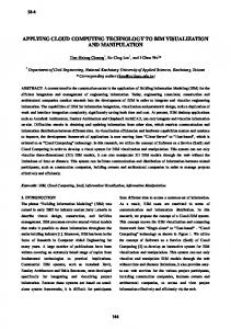
3. Design of Slip-Form Accommodating Tapered Section 3.1. Composition of the System The slip-form system is composed of the forms shaping concrete, the hydraulic jacks providing the lifting force necessary for the slip-up and the yokes sustaining the whole system. The yokes sustain the whole system including the forms and working platform and lift up the whole system by means of the lifting force transmitted from the hydraulic jacks. Accordingly, the design of the slip-form shall start by arranging the yokes and determining the capacity and number of jacks considering the scale and shape of the pylon. For the design, it is assumed that a 10 m-high pylon will be erected. The pylon is tapered vertically with a rectangular hollow cross section as generally adopted in cable-supported bridges. Moreover, one side of the pylon is planned to have a thickness varying with the height. Figure 1 describes the details of the pylon. A total of 10 yokes are arranged considering the size of the pylon’s section. Twelve hydraulic jacks with capacity of 60 kN are used (Figure 2). The forms have a
Figure 1. Cross sectional shape of the pylon. Copyright © 2013 SciRes.
AL.
Figure 2. Arrangement of yoke channels and hydraulic jacks.
height of 1.25 m based on previous erection examples and to ease the assemblage of the rebars. Traditional steel panels and lightweight GFRP panels are applied for the forms [1]. The walers playing the role of stiffener of the forms are disposed in two rows in each side. The platform has 3 levels composed respectively by a top deck, working deck and hanging deck (Figure 3).
3.2. Design of Members Adaptable to Tapered Sections The conventional erection of concrete pylons proceeds successively by placing the concrete batch up to the height of the forms, removing the forms after completion of curing and lifting of the forms. In slip-forming, placing of concrete and lifting of the forms are conducted continuously. For the construction of a tapered section, this implies that the members should be designed so as to enable continuous modification of the forms. Accordingly, this study investigates the design of the slip-form members accommodating continuously the sectional dimensions and thickness varying with the height of the pylon. First, spindles are installed in the walers to accommodate the varying dimensions of the section. The size of the forms is adjusted by controlling the length of the spindles, which makes the panels of the forms overlap. In case of large dimensional change resulting in complete overlapping of the panels, the size of the forms can also be adjusted by removing these panels. The spindles should thus be disposed where the dimensions are varying. The sectional change is planned to occur at the corners. Therefore, a total of 32 spindles are installed and disposed in two rows in each corner of the external and internal form walers (Figure 4). ENG
H. YOON ET
695
AL.
Figure 3. Three-level working platform. Figure 5. Yoke spindles.
Figure 4. Arrangement of spindles.
The forms are composed of panels in modularized structure to ease their accommodation to the sectional change. Steel panels are used for the internal form and lightweight GFRP panels are used for the external form. In this study, since the dimensional changes are planned to occur at the corners, the corner panels and ordinary panels overlap when the spindles are adjusted. When the panels overlap completely, the corresponding panels are removed to control the size of the forms. One side among the 4 sides of the pylon is planned to have a thickness varying with the height. In order to change the thickness of the pylon, the yoke should have a structure enabling to adjust freely their spacing. Therefore, bolts are inserted in the yoke channels so as to regulate the spacing between the yoke legs by adjusting the length of the bolts. Moreover, additional spindles are installed in the top deck to supplement these bolts (Figure 5).
3.3. Design Verification The slip-form shall be design to resist all the loads and Copyright © 2013 SciRes.
environments that may occur during the erection of the pylon. In this study, the yoke constituting the frame structure of the slip-form is analyzed. The stress of the yoke and capacity of the hydraulic jacks are verified for the loads under normal operational condition and suspended operational condition of the slip-form due to ultimate wind loads. The modeling of the yoke adopts beam elements (Figure 6). Its material is SS400 steel in accordance with KS D 3503 [2] with an elastic modulus of 210,000 MPa. For the accuracy of the analysis, the characteristics of the members linked to the yoke are reflected in the model. The hydraulic jacks installed at the center of the yoke channels are connected to the rods embedded in concrete and sustain all the vertical loads acting on the slip-form. Therefore, springs with large stiffness (2000 kN/m) are disposed at the nodes located at the emplacement of the jacks. Moreover, the nodes at the emplacement of the walers have their horizontal displacement restrained to consider the walers sustaining the lateral pressure of concrete. During the structural stability check, the vertical loads due to the members located at the top of the yokes including the weight, the live loads applied on the working platform, the lateral pressure of concrete and the wind loads, and the frictional loads provoked by slip-up are considered. The verification is conducted through the allowable stress method in accordance with Standard specification for temporary works [3]. The structural verification is performed using the commercial software MIDAS CIVIL 2012. Figure 7 shows the moment diagram of the yoke subjected to the permanent loads. Table 1 arranges the reactions of the hydraulic jacks and stresses of the yoke subjected to various load comENG
696
H. YOON ET Table 1. Results of yoke design check. Reaction of Flexural Axial stress Shear stress jack [kN] stress [MPa] [MPa] [MPa]
Ultimate limit state
29.5
37.87
9.62
8.78
Ultimate wind load
6.4
8.03
4.58
1.91
Check results
OK