JRRD
Volume 48, Number 1, 2011 Pages 69–82
Journal of Rehabilitation Research & Development
Development of finger-motion capturing device based on optical linear encoder Kang Li, MEng; I-Ming Chen, PhD; Song Huat Yeo, PhD; Chee Kian Lim, PhD* Robotics Research Centre, School of Mechanical and Aerospace Engineering, Nanyang Technological University, Singapore
strain gauge [6–7], and Hall Effect sensing [8] were introduced. Nevertheless, researchers can still improve these sensing methods to achieve the stringent requirements from applications in medicine and skill training, such as sensing accuracy (stability of the sensor signal and repeatability and reliability of movements), ease of wear and removal, rapid calibration, adaptation for different hand sizes, no electromagnetic interference, no temperature variation, and low cost. This article documents the development of a new handmotion monitoring and tracking device named SmartGlove based on the concept of newly invented optical linear encoders (OLEs) [9]. The OLE sensor, worn on the body crossing a joint (e.g., elbow, ankle, or wrist), captures body-joint movements. With multiple miniature OLE sensors placed on the back of all fingers, the finger-joint
Abstract—This article presents the design and validation of a wearable glove-based multifinger-motion capture device (SmartGlove), specifically focusing on the development of a new optical linear encoder (OLE). The OLE specially designed for this project is compact and lightweight and has low-power consumption. The characterization tests showed that the OLE’s digital output has good linearity and is accurate. The first prototype of SmartGlove, which uses 10 OLEs to capture the flexion/extension motion of the 14 finger joints, was constructed based on the multipoint-sensing method. A user study evaluated the SmartGlove using a standard protocol and found high repeatability and reliability in both the gripped and flat-hand positions compared with four other evaluated data gloves using the same protocol.
Key words: biomedical, calibration, design, hand-motion capture, multifinger sensing, novel sensing, optical linear encoder, rehabilitation, SmartGlove, validation.
Abbreviations: Ab/Ad = abduction/adduction, D-H = DenavitHartenberg, DIP = distal interphalangeal, DOF = degree of freedom, F/E = flexion/extension, ICC = intraclass correlation coefficient, IP = interphalangeal, MCP = metacarpophalangeal, OLE = optical linear encoder, PCB = printed circuit board, PIP = proximal interphalangeal, SD = standard deviation, SPI = serial peripheral interface, TM = trapeziometacarpal, USB = Universal Serial Bus. *Address all correspondence to Chee Kian Lim, PhD; Robotics Research Centre, School of Mechanical and Aerospace Engineering, Nanyang Technological University, 50 Nanyang Ave, N3-0la-01, Singapore 639798; 65-6790-5568; fax: 65-6793-5921. Email:
[email protected] DOI:10.1682/JRRD.2010.02.0013
INTRODUCTION Being the intricate and prehensile parts of the human body, our hands are the primary agents that physically interact with the external world. We use our hands to perform various everyday activities. Hence, monitoring and tracking human hand motion are crucial applications in rehabilitation, skill training, entertainment, etc. To capture the human hand’s motion, researchers have developed many sensing methods in the past few decades. Beyond optical [1], acoustic [2], and magnetic sensing [3], innovative techniques such as fiber optics [4–5], 69
70 JRRD, Volume 48, Number 1, 2011
movements can be captured accurately. The SmartGlove aims to achieve high-performance hand- and finger-motion tracking and monitoring at an affordable cost for wide adoption. Compared with currently available hand-capturing devices, the critical OLE sensing element costs little and is compact, lightweight, and immune to temperature or electromagnetic interferences. Ten finger OLEs form a soft exoskeleton structure and are mounted quickly on the glove. The soft skeleton structure also makes SmartGlove able to fit all hand sizes. The device can interface with general computing systems through wired and wireless standard interfaces (e.g., USB [Universal Serial Bus] and Bluetooth). Moreover, SmartGlove can act both as a stand-alone device and as a part of a Body Sensor Network* with other OLE sensors on body joints to track entire human body movements from the hand (fine motion) to the limbs (gross motion) in a uniform interface. In this article, we describe the novel sensing principle of the SmartGlove and its relationship with the hand kinematics model and describe the SmartGlove prototype and system implementations. Next, we discuss the calibration of the SmartGlove and then present the sensor performance evaluation, in terms of repeatability, reliability, and fast response and user test on the SmartGlove device as a whole. The final user evaluation and performance analysis indicate that the new SmartGlove outperforms most of the current systems in terms of the given standard tasks.
METHODS AND RESULTS
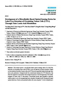
OLE is free to slide along its longitudinal axis. When the elbow bends, the bending causes the skin to stretch. This stretch is translated into a linear displacement and can be captured by the OLE assembly. However, the OLE developed for the SmartSuit project is meant for limb-motion capture. The size of the sensor assembly is too large for the finger-joint motion capture. Thus, an inverted sensing principle for OLE is formulated for the SmartGlove project. As shown in Figure 1(b), in the inverted OLE, the encoder is fixed on the finger segment to capture the displacement of the moving strip. Without the moving mechanism, the size of the OLE for the SmartGlove can be reduced significantly for fulfilling the dimensional requirement. From the studies of human hand anatomy, obviously, the joint axis is not fixed as the finger bends. However, the displacement of the change of the finger-joint center is quite small compared with the dimension of the fingers. Hence, in this study, we assume that the finger-joint center is a fixed rather than a moving point. Because of this assumption, the finger-joint rotation can be modeled with a circular disk. The strip is placed on the surface of the finger with one end fixed (Figure 1(a)). As the finger joint bends, it stretches the skin. This stretch is translated into a linear displacement and the OLE captures it. As shown in Figure 1(b), when the joint bends, the movement of the two segments can be approximated by the rotation of a circular disk when the center of the joint becomes the center of the disk. The radius of the circle is based on the biometric data of the subject considered and can be approximately obtained through physical measurement.
System Architecture Inverted Optical Linear Encoder Sensing Principle The inverted OLE sensing principle is transformed from the sensing principle proposed in the SmartSuit (Nanyang Technological University, Singapore) project [9]. In the SmartSuit project, joint angle of a human body joint is obtained through a new OLE sensor. The OLE is attached to a wire that is fixed on one forearm, while the OLE assembly is fixed on the upper arm. The wire is displaced along the circumference of the joint (Figure 1(a)). The
*Body
Sensor Network (or BSN) originated at Imperial College, London, England, in 2002. Under the direction of Professor GuangZhong, it seeks to develop the body-monitoring potential of tiny computers the size of a pinhead, miniature microsensors, and wireless network technology.
Figure 1. (a) Regular optical linear encoder (OLE) sensing principle and (b) inverted OLE sensing principle. OLE is fixed on finger segment to capture displacement (L0) of moving strip. R0 = radius of finger joint, 0 = bend angle of joint.
71 LI et al. Development of finger-motion capturing device
Assume the radius of the joint is R0 and the bend angle of the joint is 0; by measuring the displacement (L0) of the strip with the OLE, one can estimate 0 by
Multipoint Sensing Principle The multipoint sensing principle is an extension of the inverted single-point OLE sensing. The single-point OLE sensor detects joint flexion displacement through one degree of freedom (DOF) linear movement of the sensor outputs. The sensor incorporates a thin OLE strip sliding in a base structure in which the optical reader head acquires the movement of the strip. With the base sensor structure fixed onto one limb segment and the distal end of the OLE strip fixed to the neighboring limb segment, the sensor can interpret the linear movements of the strip caused by the joint movement as joint angles with suitable biometric data. Essentially, the OLE sensor acts like a wearable soft exoskeleton with sensing capability. The OLE sensor can be placed at the wrist, elbow, and shoulder, as well as the ankle, knee, and hip joints of different DOFs. Two or three OLE sensors together can detect joint motions of multiple DOFs. The basic working principle of SmartGlove uses a variation of the OLE principle by placing multiple OLEs in series on different finger segments to capture the displacements of different detecting points on a single OLE strip. This OLE strip passes through all OLEs on the same finger. Thus, it is called the “multipoint” OLE. As shown in Figure 2(a), three disks (from left to right) represent three in-line joints with radii of R3, R2, and R1, respectively. Denote their bend angles in Figure 2(b) as 1, 2, and 3, respectively. Three OLEs are to be placed and fixed at positions A, B, and C as shown in Figure 2. Assume the displacement readings of the three OLEs are D1, D2, and D3. Because of the accumulated displacement at the distal joints, we have
and
Figure 2. Multipoint sensing principle, where optical linear encoder (OLE) strip passes through all OLEs on same finger. (a) OLE at initial position— three in-line joints of radius of R3, R2, and R1; (b) conversion from displacements (L1, L2, L3) to bend angles of 1, 2, and 3, respectively; and OLEs placed and fixed at positions A, B, and C.
Because of the natural arches of hand, multipoint sensing can be adopted in finger-motion capture. As shown in Figure 3, the hand has five longitudinal arches, one for each of the five digital rays. Each arch is composed of a metacarpal and its phalanges, linked by the metacarpophalangeal (MCP), proximal interphalangeal (PIP), and distal interphalangeal (DIP) joints. (The longitudinal arch for thumb is linked by the MCP and interphalangeal [IP] joints [10]). As introduced in the hand kinematics section later (page 73), at least 14 joint flexion/extension (F/E) motions need to be captured for the hand to perform basic multifinger sensing, and these 14 joints are all within the five longitudinal arches. Hence, with one strip for each longitudinal finger arch, multiple OLEs use the multipoint sensing method to capture the finger’s movement. In other words, multipoint sensing on a single encoding strip can easily be used for sensing the multiple DOF movements of an articulated object.
72 JRRD, Volume 48, Number 1, 2011
Human Hand Overview Based on anatomical and medical hand analysis of previous studies and research, the hand skeleton model has 23 internal DOFs (Figure 4) [11–12]. Each of the four fingers has four DOFs. The DIP and PIP joints both have one DOF, and the remaining two DOFs are located at the MCP joint. Different from the four fingers, the
Figure 3. Arches of hand.
Figure 4. Human hand skeleton model. DIP = distal interphalangeal, HM = hamate metacarpal, IP = interphalangeal, MCP = metacarpophalangeal, PIP = proximal interphalangeal, TM = trapeziometacarpal.
thumb has five DOFs. Two DOFs are at the trapeziometacarpal (TM) joint (also referred to as the carpometacarpal joint), and two are at the MCP joint. The remaining one DOF of the thumb is at the IP joint. The basic F/E and abduction/adduction (Ab/Ad) of the thumb and fingers are performed by the articulation of the 21 DOFs just described. As shown in Figure 5, the F/E motions are used to describe rotations toward and away from the palm, which occur at every joint within the hand. The abduction is the movement of separation (e.g., spreading fingers apart), and the adduction motion is the movement of approximation (e.g., folding fingers together). The Ab/Ad only occurs at each finger’s MCP joint and at the thumb’s MCP and TM joints. Another two internal DOFs are at the base of the fourth and fifth (ring and little finger’s) metacarpals, which perform the curve or fold actions of the palm. Although the human hand is highly articulated with up to 23 internal DOFs, it is also highly constrained. By applying those constraints, one can reduce the number of DOFs in the hand, which in turn makes the human handmotion capture more cost-efficient. Besides, the application of the hand-motion constraints synthesizes natural hand motion to produce realistic hand animation. A common constraint used based on the hand anatomy states that to bend the DIP joints of the index, middle, ring, and little fingers, the corresponding PIP joints must also be bent (Figure 6) [13–14]. A common approach used to reduce the total DOFs of a hand can be derived based on the hand anatomy, where the bending angles of DIP joints of the index, middle, ring, and little fingers are associated with the PIP joints based on the following relationship: DIP = 2/3 PIP, where DIP refers to the flexion angle of the DIP joint and PIP refers to the flexion angle of the PIP joint.
Figure 5. Denotation of flexion/extension and abduction/adduction motions of thumb and fingers.
73 LI et al. Development of finger-motion capturing device
Human Hand Kinematics Modeling The human hand is modeled with a hierarchical tree structure that consists of rigid links and joints. Each joint consists of one or two DOFs. We show this hierarchical structure in Figure 7 and describe each joint’s position using Denavit-Hartenberg (D-H) transformation with reference to the heel of the hand (the world coordinate system x 0' , y'0 , z 0' ) [15]. The posture of each finger ray
Figure 6. Bending constraints between distal interphalangeal (DIP) and proximal interphalangeal (PIP) joints. DIP = flexion angle of DIP joint, PIP = flexion angle of PIP joint.
(labeled 1 to 5 from the thumb to the little finger as shown in Figure 7) is represented under a local coordinate system. With D-H transformation, the position of each joint can be transformed from the local coordinates to the world coordinates sequentially. As shown in Figure 7, five-finger rays can be divided into three different groups based on the different kinematic structure (thumb ray with five DOFs, index and middle finger rays with four DOFs, and ring and little finger rays with five DOFs). Taking the thumb ray as an example to explain the implementation of the D-H method, we define D-H parameters as follows: • Joint anglei = the angle of rotation from the xi–1-axis to the xi-axis about the zi–1-axis. It is the joint variable if the ith joint is rotary. • Joint distance di = the distance from the origin of the (i–1)th coordinate system to the intersection of the zi–1axis and the xi-axis along the zi–1-axis. It is the joint variable if the ith joint is prismatic. • Link length i = the distance from the intersection of the zi–1-axis to the origin of the ith coordinate system along the xi-axis. • Link twist angle i = the angle of rotation from the zi–1-axis to the zi-axis about the xi-axis. The transformation matrix is
The kinematic model for the thumb is shown in Figure 8, and the D-H parameters are listed in Table 1. With these parameters, the D-H transformation matrix of the thumb tip’s coordinate frame with reference to the local coordinate system is
With respect to the world coordinate system (the heel of hand as shown in Figure 7), an additional transformation matrix is needed to represent the position vector that is defined as Figure 7. Human hand kinematic model. Finger rays labeled 1 to 5 from thumb to little finger. Thumb is reversed. l' = link length, ' = abduction angle, x,z = joint axes.
74 JRRD, Volume 48, Number 1, 2011
Therefore, the thumb tip’s coordinate frame with respect to the world coordinate system is defined by
The implementation of D-H transformation on the other four fingers is similar. System Configuration As shown in Figure 9. The SmartGlove system consists of five multi-OLE strips (each includes two OLEs), and a microcontroller. The multi-OLE strips will send the
Figure 9. System configuration of optical linear encoder (OLE) for SmartGlove. PC = personal computer, PDA = personal digital assistant, USB = Universal Serial Bus.
appropriate F/E motion data of each finger joint to the microcontroller, which will synthesize all the information sent to it from the multiple OLEs. Then, using a forward human hand kinematics model embedded into the gateway (i.e., a personal digital assistant device), the microcontroller will transmit the captured motion data to a remote robot, virtual reality system, or computer for further analysis and application through wired or wireless communication. SmartGlove Prototype
Figure 8. Kinematic model for thumb, showing link lengths (l), joint angles ( ), and joint axes (x,z) of interphalangeal (IP), trapeziometacarpal (TM), and metacarpophalangeal (MCP) joints. Table 1. Denavit-Hartenberg parameters.
ith Joint 1 2 3 4 5
i 10 11 12 13 14
di 0 0 0 0 0
i –90° 90° –90° 0° 0°
i 0 l 11 0 l 12 l 13
i = joint angle, di = joint distance, i = link twist angle, i = link length.
Optical Linear Encoder Module The OLE module is the sensing module in the system that includes three basic units: interface (the customized printed circuit board [PCB] board), the sensing (sensor and lens), and housing units (the customized baseplate and strip), as shown in Figure 10. The sensing unit is fixed in the housing unit to obtain the displacement of strip and to communicate with the microcontroller through the interface unit. The sensor used in OLE is Avago’s optical mouse sensor product ADNS-3530 [16], which is based on Optical Navigation Technology (Avago Technologies; San José, California) that measures changes in position by optically acquiring sequential surface images (frames) and mathematically determining the direction and magnitude of movement. Surface mounting of the ADNS-3530 sensor on a PCB requires a compact OLE design.
75 LI et al. Development of finger-motion capturing device
MOTION pin [16], which is used to get motion signal from the OLE, and voltage translators are added to the four SPI pins (serial clock, master output slave input, master input, slave output, and chip select) so that the different voltage levels between the microcontroller and the OLE are not violated.
Figure 10. Optical linear encoder (OLE) module (dimensions in millimeters) that includes interface, sensing, and housing units.
The housing unit holds the optical navigation sensor and the moving strip made of Delrin. According to the performance of ADNS-3530, the distance between the lens and the moving strip determines the resolution of the result. Based on the data sheet for obtaining high resolution of the sensor, the distance should be within the range 0.77 to 0.97 mm. Furthermore, the surface material of the strip also affects the sensor’s resolution. To ensure the strip slides smoothly in the housing unit, one must have a gap between the strip and the baseplate. Consequently, for the stable readout, white Formica is the ideal choice for surface material of the strip because the mean resolution is very stable within the predefined range (0.77 to 0.97 mm). The whole OLE module is a compact size of 13 12 4 mm, and the cost for one OLE module is within US$50. Microcontroller SmartGlove uses the Arduino Diecimila/Bluetooth [17], which is based on the Atmega168 (both systems developed by SparkFun Electronics; Boulder, Colorado). Arduino is an open-source physical computing platform based on a simple input/output board. The open-source programming language for the Arduino is Wiring/Processing. The microcontroller communicates with the OLEs using serial peripheral interface (SPI) protocol and sending all the motion data to personal computer using USB/Bluetooth. To connect 10 OLEs easily, an interface board is designed to work with the Arduino board. Because the onboard USB chip can only generate a maximum current of 50 mA, a voltage regulator is designed in the interface board to draw 500 mA current directly from the USB port to ensure that the microcontroller powers up the 10 OLEs. For safe operation, open-collector buffers are added to the
Glove Design To make the glove-type OLEs sensitive, the user should ensure the glove fits nicely on the hand. On the other hand, the glove should not hinder free motion of the hand. Therefore, soft and stretchable fabric is used for the SmartGlove. In this project, we used two different fabrics: the semistretching fabric, which stretches only in a single direction, and the stretching fabric, which stretches in all directions. The glove uses stretching fabric for the back side of the MCP joints and semistretching fabric for the palm side so that stretching along the finger direction is avoided. Thus, the glove has good elasticity to fit users’ hands. For ease of the replacement or maintenance of the sensors, the OLEs are mounted onto the glove with Velcro and the microcontroller connects OLEs with ribbon wires. Thus, the glove can be separated from the OLEs and all the hardware for cleaning. This feature is a big leap toward using such data gloves in common daily living. Several photographs of the SmartGlove prototype are shown in Figure 11.
Figure 11. SmartGlove prototype.
76 JRRD, Volume 48, Number 1, 2011
Calibration Method Kadouche et al. proposed four simple calibration postures for the SmartGlove that are easy to perform to acquire the approximated standard angles for each of the 10 OLEs (Figure 12) [18]: • Posture 1 corresponds to an angle of 0° for all 10 measured joints and also the homing position for the 10 OLEs. • Posture 2 defines the angles for the thumb’s MCP and IP joints: ( 11 = 45°; 12 = 90°). • Posture 3 defines a 90° angle for all the fingers’ MCP joints: ( 21, 31, 41, and 51 = 90°). • Posture 4 defines a 90° angle for all the fingers’ PIP joints: ( 22, 32, 42, and 52 = 90°). These four calibration postures are simple and easy to perform; however, the accuracy is not ideal because each joint has only two angles (0° and 90°) for calibration and also the joints can only approximately reach the desired degree without using external tools. Thus, a single-joint calibration, which calibrates each OLE with a specially designed tool with five known angles (Figure 13), is proposed in this project for more precise calibration. With the finger joint attached on different edges of the calibration block (take the calibration of the index finger’s PIP joint as an example shown in Figure 13), the OLE sensor can obtain four standard angles. Based on these angles, a precise calibration for one single joint can be done.
OLE Characterization Tests We performed two tests to evaluate the OLE on both a wooden finger and a human finger. To characterize the OLE’s performance without considering the effect of finger skin deformation, we used a wooden finger in the first test. As shown in Figure 14, the OLE is fastened to the wooden finger, with the strip wrapped over the knuckle. When the wooden finger bends, the OLE can read the displacement of the strip, and based on the working principle of the OLE,
Figure 13. Calibrate index finger’s proximal interphalangeal joint in degrees (°) using calibration block.
Preliminary Experimental Data We performed two sets of experiments. The first set of experiments was to verify that our innovative OLE is suitable to be used in sensing human-finger motion. The second set of experiments was to characterize the repeatability and reliability of the SmartGlove when 10 OLEs work together.
Figure 12. Calibration postures (a) 1, (b) 2, (c) 3, and (d) 4 of optical linear encoder.
Figure 14. Setup of optical linear encoder’s (OLE’s) wooden-finger test.
77 LI et al. Development of finger-motion capturing device
the bending angle could be calculated. By comparing the angle captured from the OLE with the angle measured directly from the protractor stick to the wooden finger, one can examine the bending performance of the OLE. The OLE’s readout data are plotted against the angle obtained from the protractor in Figure 15. It shows good repeatability, as well as linearity, in the OLE reading in the bending test between 0° and 90°, which is the normal motion range of finger joints. Also, the linearity of the OLE reading under the bending condition can be calculated as
croelectronics [Geneva, Switzerland] [19]) attached to the second knuckle of the index finger to measure the bending angle of the PIP joint. The palm is placed on a flat metal plate as a stable reference during the test. In the humanfinger test, the PIP joint of the index finger is bent back and forth three times. In the measurement, data from the OLE and the accelerometer are recorded as shown in Figure 17. Comparing the angular data from the OLE with the angular data from accelerometer (the tilt angle calculated from the three orthogonal acceleration components [20]), we found that the results are very close and the difference
where d = average difference and r = range. The radius (R) of the rotation joint can be obtained as
The radius of the rotation joint measured by vernier caliper is 6 mm, which is very close to the value calculated in Equation 8. The OLE has shown to work in the bending test on a wooden finger. However, the human finger is different from the wooden finger because of the skin deformation that may affect the measure result. Hence, further testing on a real human finger is necessary to test the accuracy of the OLE in deployment status. The setup of the human-finger test is shown in Figure 16. The OLE is attached to the first knuckle of the index finger, with an accelerometer (LIS3LV02DQ from STMi-
Figure 15. Result of optical linear encoder’s (OLE’s) wooden finger test.
Figure 16. Setup of optical linear encoder’s (OLE’s) human-finger test.
Figure 17. Recorded results of optical linear encoder (OLE) and accelerometer (ACC) of human-finger test.
78 JRRD, Volume 48, Number 1, 2011
between the OLEs and the accelerometer is within 1°. These findings indicate that the OLE is suitable for human-finger motion capture and produces good results. The SmartGlove evaluation procedure adopted in this project is based on the standardized evaluation protocols for sensor glove devices proposed by Wise et al. for the evaluation of the Data Glove [21]. Similar tests are also adopted by Williams et al. for the SIGMA Glove evaluation [22], Dipietro et al. for the Humanware Humanglove evaluation [23], Simone et al. for Shadow Monitor evaluation [24], and Gentner and Classen for a sensor glove evaluation [25]. SmartGlove Performance Tests We collected data from five nondisabled male students aged 22 to 27 years, with comparable hand size and no hand-movement disorders. All subjects were righthanded, and the glove was placed on the right hand. We performed calibration using the calibration block on each subject before performance tests. The standardized experiment protocols included four tests. However, focusing on repeatability and reliability of multiple measurements over a single data collection session, we adopted two tests (Grip Test and Flat Test). We used the Grip Test (a gripped-hand position) and the Flat Test (a flat-hand position) to analyze the repeatability and reliability. Five sets of measurement were performed in each test on each subject, and each set of measurements includes 10 grip/release actions. In the Grip Test, the subject gripped the prepared cylindrical reference metal bar (with the radius of 45 mm) for 6 seconds and then released for 6 seconds (Figure 18).
Figure 18. Grip Test of SmartGlove. (a) Subject griped the prepared cylindrical reference metal bar for 6 s and then released for 6 s. During release, (b) subject’s hand was placed flat on table.
During the release, the subject placed the hand flat on the table. This grip/release cycle is repeated 10 times. Repeating measurements were taken from each OLE during the grip phase. A single data block was composed of data from 10 grip/release actions on one OLE (Figure 19 includes 10 data blocks for 10 OLEs). The test was repeated five times without the glove removed between successive sets; 50 grip/release cycles were done. In the Flat Test, the subject placed the hand on the table and alternately raised the hand and lightly flexed the fingers and then returned the hand to the tabletop (Figure 20). Each hand position lasted 6 seconds, and the flat/flex cycle was repeated 10 times. The repeatability of the flat-hand position was explored in this test. To keep the hand and fingers in the same position during the flat period, we drew an outline of the subject’s hand profile on a paper and placed it on the table.
Figure 19. Sample data block (Grip Test) of MCP, IP, and PIP joints for thumb, index, middle, ring, and little fingers. IP = interphalangeal, MCP = metacarpophalangeal, PIP = proximal interphalangeal.
79 LI et al. Development of finger-motion capturing device
At the flat position, the subject was asked to place the hand and fingers inside this drawn profile as shown in Figure 20. As was done in the Grip Test, the subject repeated this test five times without removing the glove between consecutive measurements; 50 flex/flat cycles were done. Repeatability was indicated by the range and standard deviation (SD); consequently, the average range and SD were obtained from each subject in each test as shown in Figure 21. Looking into each OLE across subjects 1 to 5 for each test, the histogram of Figure 22 summarizes the performance. Reliability is indicated by intraclass correlation coefficient (ICC) [23]. We performed an ICC analysis for each test and for each OLE (we used Microsoft Excel [Microsoft Corp; Redmond, Washington] to calculate ICC). The ICC values in Table 2 show consistency from one data block to another with no particular OLE showing significant lower reliability than the overall mean.
Figure 22. Histogram of averaged range and standard deviation (SD) of angle (°) for optical linear encoder (OLE) 1–10 in each test.
Table 2. Intraclass correlation coefficient of reliability of SmartGlove for Grip and Flat Tests. Thumb
Index
Middle
Right
Little
MCP PIP
MCP PIP
MCP PIP
MCP PIP
Test
Avg MCP
IP
Grip
0.937 0.954
0.882 0.963
0.913 0.987
0.948 0.957
0.969 0.964
0.947
Flat
0.955 0.968
0.893 0.966
0.908 0.976
0.955 0.968
0.958 0.979
0.953
Overall
—
—
—
—
—
—
—
—
—
—
0.950
IP = interphalangeal, MCP = metacarpophalangeal, PIP = proximal interphalangeal, Avg = average.
Figure 20. Flat Test performance of SmartGlove: (a) flat and (b) flexed.
Figure 21. Histogram of averaged range and standard deviation (SD) of angle (°) of SmartGlove in each Flat and Grip Test for subjects 1–5.
DISCUSSION A new hand/finger-motion capturing device based on multipoint OLE sensing principle was designed and tested. The specially designed OLE for multipoint sensing had characteristics such as high resolution (can detect the strip’s motion up to 20 inch/s in linear speed and 80 m/s2 in acceleration), fast speed (at least 150 Hz), low power (3.6 mA), and low cost. The OLE showed good linearity (99.42% in bending condition), repeatability, and accuracy (within 1° compared with the accelerometer) in deployment status. Additionally, the OLE is compact (13 12 5 mm) and lightweight (10 g), which makes attaching the glove to perform hand-motion capture easy. Our system is the first tracking system that utilizes OLEs to perform the task of human hand-motion capture. The novelty and simplicity in technology and implementation realized the objective of a low-cost sensing module for human-joint measurement. The
80 JRRD, Volume 48, Number 1, 2011
cost of a single OLE module (US$10) + microcontroller (US$5) + circuitry and mechanical parts (US$10) is approximately US$25 [26].
CONCLUSIONS As shown in Table 3, compared with the previous four studies, the SmartGlove showed relatively good results in both repeatability and reliability and was within the measurement reliability of manual goniometry. Future research will involve using the same OLE to sense the finger’s Ab/ Ad, increasing robustness in design, integrating other sensors, and designing applications for SmartGlove for tracking high-precision hand motion. Figure 23 presents a graphical user interface for the proposed SmartGlove.
ACKNOWLEDGMENTS Author Contributions: Study concept and design: K. Li, I-M. Chen, S. H. Yeo, C. K. Lim. Acquisition of data: K. Li, C. K. Lim. Analysis and interpretation of data: K. Li, C. K. Lim, I-M. Chen, S. H. Yeo. Drafting of manuscript: K. Li, C. K. Lim, I-M. Chen, S. H. Yeo. Critical revision of manuscript for important intellectual content: I-M. Chen, S. H. Yeo, C. K. Lim.
Table 3. Results (range [] SD) of SmartGlove compared with Wise et al. data glove (VPL Research, Inc), Dipietro et al. Humanglove (Humanware), Simone et al. Shadow Monitor, and Gentner and Classen WU Glove. Grip Test
Flat Test
Total
Range SD
Range SD
Range SD
Wise et al. (1990) Data Glove (VPL Research, Inc) [1]
6.50
2.60
4.50
6.50
4.50
2.60
0.94
Dipietro et al. (2003) Humanglove (Humanware) [2]
7.47
2.44
3.84
7.47
3.84
2.44
0.7~1.0
Simone et al. (2007) Shadow Monitor [3]
5.22
1.61
1.49
5.22
1.49
1.61
0.95
Gentner and Classen (2009) WU Glove [4]
6.09
1.94
2.61
6.09
2.61
1.94
0.93
SmartGlove
4.56
1.57
2.02
4.56
2.02
1.57
0.95
Glove Tested
ICC
1. Wise S, Gardner W, Sabelman E, Valainis E, Wong Y, Glass K, Drace J, Rosen JM. Evaluation of a fiber optic glove for semi-automated goniometric measurement. J Rehabil Res Dev. 1990;27(4):411–24. [PMID: 2089151] 2. Dipietro L, Sabatini AM, Dario P. Evaluation of an instrumented glove for hand-movement acquisition. J Rehabil Res Dev. 2003;40(2):179–89. [PMID: 15077642] DOI:10.1682/JRRD.2003.03.0181 3. Simone LK, Sundarrajan N, Luo X, Jia Y, Kamper DG. A low cost instrumented glove for extended monitoring and functional hand assessment. J Neurosci Methods. 2007;160(2):335–48. [PMID: 17069892] DOI:10.1016/j.jneumeth.2006.09.021 4. Gentner R, Classen J. Development and evaluation of a low-cost sensor glove for assessment of human finger movements in neurophysiological settings. J Neurosci Methods. 2009;178(1):138–47. [PMID: 19056422] ICC = intraclass correlation coefficient, SD = standard deviation.
Figure 23. SmartGlove graphical user interface: (a) hand visualization and animation and (b) control panel.
81 LI et al. Development of finger-motion capturing device
Statistical analysis: K. Li, I-M. Chen, S. H. Yeo, C. K. Lim Obtained funding: I-M. Chen, S. H. Yeo. Administrative, technical, or material support: K. Li, C. K. Lim. Study supervision: I-M. Chen, S. H. Yeo. Financial Disclosures: The authors have declared that no competing interests exist. Funding/Support: This material was based on work supported in part by the Agency for Science, Technology and Research, Singapore, under Science and Engineering Research Council grant 0521180050, and Media Development Authority, Singapore, under National Research Foundation grant IDM004-005. Additional Contributions: Mr. Kang Li is no longer at the Nanyang Technological University, Singapore. Participant Follow-Up: The authors do not plan to inform participants of the publication of this study. However, participants have been encouraged to check the study Web site for updated publications.
REFERENCES 1. Goebl W, Palmer C. Anticipatory motion in piano performance. J Acoust Soc Am. 2006;120(5):3004. 2. Power glove user guide. El Segundo (CA): Mattel, Inc; September 2007. 3. Mitobe K, Kaiga T, Yukawa T, Miura T, Tamamoto H, Rodgers A, Yoshimura N. Development of a motion capture system for a hand using a magnetic three-dimensional position sensor. Boston (MA): ACM SIGGRAPH Research posters: Motion capture and editing; 2006. 4. Fifth Dimension Technologies [Internet]. Irvine (CA): 5DT Inc; c1999–2005 [updated 2010 Nov 30; cited 2007 Sep 1]. Available from: http://www.5dt.com. 5. Measurand Shape Advantage [Internet]. Fredericton (New Brunswick): Measurand Inc; 2007 [cited 2007 Sep 1]. Available from: http://www.measurand.com. 6. Immersion Corporation: Who’s using haptics? [Internet]. San Jose (CA): Immersion Corp; c2010. Available from: http://www.immersion.com. 7. DGTech Engineering Solutions: Vhand Glove [Internet]. Bazzano (Italy): DGTech; [cited 2007 Sep 1]. Available from: http://www.dg-tech.it/vhand/eng/. 8. Humanware S.R.L. [Internet]. Pisa (Italy): Humanware; c1996–2010 [updated 2009 Sep 24; cited 2007 Sep 1]. Available from: http://www.hmw.it/prodotti_e.html. 9. Lim KY, Goh FY, Dong W, Nguyen KD, Chen IM, Yeo SH, Duh HB, Kim CG. A wearable, self-calibrating, wireless sensor network for body motion processing. IEEE International Conference on Robotics and Automation (ICRA 2008); 2008 May 19–23; Pasadena, CA. Los Alamitos (CA): IEEE International; 2008. p. 1017–22. 10. Lin J, Wu Y, Huang TS. Modeling the constraints of human hand motion. Proceedings of the Workshop on Human
Motion; 2000 Dec 7–8. Los Alamitos (CA): IEEE International; 2000. p. 121–26. 11. Wu Y, Huang TS. Human hand modeling, analysis and animation in the context of HCI. Proceedings of the International Conference on Image Processing; 1999; Japan. p. 6–10. 12. Rhee T, Neumann U, Lewis JP. Human hand modeling from surface anatomy. Proceedings of the 2006 Symposium on Interactive 3D Graphics and Games; 2006 Mar 14–17; Redwood City, CA. New York (NY): ACM; 2006. p. 27–34. 13. Lee J, Kunii TL. Model-based analysis of hand posture. IEEE Comput Graph Appl. 1995;15(5):77–86. DOI:10.1109/38.403831 14. Denavit J, Hartenberg RS. A kinematic notation for lowerpair mechanisms based on matrices. Trans ASME J Appl Mech. 1955;23:215–21. 15. Yu HL, Chase RA, Strauch B. Atlas of hand anatomy and clinical implications. St. Louis (MO): Mosby; 2004. 16. Avago Technologies: Your Imagination, Our Innovation [Internet]. San Jose (CA): Avago Technologies; c2005–2010 [cited 2008 May 3]. Available from: http://www.avagotech.com. 17. Arduino [Internet]. [cited 2009 Jun 30]. Available from: http://www.arduino.cc. 18. Kadouche R, Mokhtari M, Maier M. Modeling of the residual capability for people with severe motor disabilities: Analysis of hand posture. LNCS. 2005;3538:231–35. DOI:10.1007/11527886_30 19. STMicroelectronics [Internet]. Geneva (Switzerland): STMicroelectronics; c2010 [cited 2008 Jun 5]. Available from: http://www.st.com. 20. Dong W, Lim KY, Goh YK, Nguyen KD, Chen IM, Yeo SH, Duh BL. A low-cost motion tracker and its error analysis. Proceedings of the IEEE International Conference on Robotics and Automation; 2008 May 19–23; Pasadena, CA. Los Alamitos (CA): IEEE International; 2008. p. 311–16. 21. Wise S, Gardner W, Sabelman E, Valainis E, Wong Y, Glass K, Drace J, Rosen JM. Evaluation of a fiber optic glove for semi-automated goniometric measurement. J Rehabil Res Dev. 1990;27(4):411–24. [PMID: 2089151] DOI:10.1682/JRRD.1990.10.0411 22. Williams NW, Penrose JM, Caddy CM, Barnes E, Hose DR, Harley P. A goniometric glove for clinical hand assessment. Construction, calibration and validation. J Hand Surg Br. 2000;25(2):200–207. [PMID: 11062583] DOI:10.1054/jhsb.1999.0360 23. Dipietro L, Sabatini AM, Dario P. Evaluation of an instrumented glove for hand-movement acquisition. J Rehabil Res Dev. 2003;40(2):179–89. [PMID: 15077642] DOI:10.1682/JRRD.2003.03.0181 24. Simone LK, Sundarrajan N, Luo X, Jia Y, Kamper DG. A low cost instrumented glove for extended monitoring and functional hand assessment. J Neurosci Methods. 2007; 160(2):335–48. [PMID: 17069892] DOI:10.1016/j.jneumeth.2006.09.021
82 JRRD, Volume 48, Number 1, 2011
25. Gentner R, Classen J. Development and evaluation of a lowcost sensor glove for assessment of human finger movements in neurophysiological settings. J Neurosci Methods. 2009;178(1):138–47. [PMID: 19056422] DOI:10.1016/j.jneumeth.2008.11.005 26. Nguyen K, Chen I, Luo Z, Yeo S, Duh H. A wearable sensing system for tracking and monitoring of functional arm movement. IEEE/ASME Trans Mechatron. 2011;(99):1–8.
Submitted for publication February 8, 2010. Accepted in revised form September 14, 2010.
This article and any supplementary material should be cited as follows: Li K, Chen IM, Yeo SH, Lim CK. Development of fingermotion capturing device based on optical linear encoder. J Rehabil Res Dev. 2011;48(1):69–82. DOI:10.1682/JRRD.2010.02.0013