Dec 10, 2013 - for the Bachelor of Engineering (Honours). (Electrical ... (GUIDE) together with a structured programming approach have been used to design.
DEVELOPMENT OF GRAPHICAL USER INTERFACE FOR MICROWAVE FILTER DESIGN
by DJENGOMEMGOTO GERARD
Dissertation submitted to the Department of Electrical & Electronic Engineering in partial fulfilment of the requirements for the Bachelor of Engineering (Honours) (Electrical & Electronic Engineering)
December 2013
Universiti Teknologi PETRONAS Bandar Seri Iskandar 31750 Tronoh Perak Darul Ridzuan
© Copyright 2013 by Djengomemgoto Gerard, 2013
i
CERTIFICATION OF APPROVAL
DEVELOPMENT OF GRAPHICAL USER INTERFACE FOR MICROWAVE FILTER DESIGN by DJENGOMEMGOTO GERARD
A project dissertation submitted to the Department of Electrical & Electronic Engineering Universiti Teknologi PETRONAS in partial fulfilment of the requirement for the Bachelor of Engineering (Honours) (Electrical & Electronic Engineering)
Approved by:
____________________ Dr. Wong Peng Wen Project Supervisor Universiti Teknologi PETRONAS Tronoh, Perak December 2013
ii
CERTIFICATION OF ORIGINALITY
This is to certify that I am responsible for the work submitted in this project, that the original work is my own except as specified in the references and acknowledgements, and that the original work contained herein have not been undertaken or done by unspecified sources or persons.
___________________________________________
DJENGOMEMGOTO GERARD
iii
ABSTRACT Microwave filters play a sterling role in wireless communication systems and they are used to discriminate between wanted and unwanted signal frequencies. Designing microwave filter is a long process in going from the given specification through the synthesis and simulation to the final prototype. However, due to the unavailability of synthesized theoretical values of reactive elements in the market, the result may disagree with the expected output. Moreover, the existing software tools cover only conventional filter topologies; modern microwave filter topologies such as Ultra Wideband (UWB) filter are not yet incorporated into these software tools. In addition, they are costly and not easy to use. This research project aims at developing a low-cost, time-effective and a standalone graphical user interface (GUI) that will be used to design microwave filters. Throughout the projects, the main theory behind the technology of microwave filters, their generalized mathematical equations and the analysis of their different circuit topologies have been reviewed. This review helps to extract the necessary information needed for the design of microwave filters. Besides, the guiding principles and the underlying engineering factors for a successful and informationoriented GUI were also highlighted. To carry out the project, the High-Level GUI Development Environment (GUIDE) together with a structured programming approach have been used to design the GUI, and to program its related functionalities. The frequency responses are generated by using the generalized equation of each filter class and type; and by using their different circuit topologies (Shunt or Series topology). The GUI can also provide reactive element values from given specification. Moreover, the features for the design of ultra wideband (UWB) band-pass filter, capacitively coupled and combline filter are also incorporated into the stand-alone application. The finalized prototype will serve both industries and educational institutions.
iv
ACKNOLEDGEMENT First and foremost, I would like to show and present my humble gratitude to Universiti Teknologi Petronas for putting in place this dynamic educational system for its students, to PETRONAS for its financial, physical and moral support throughout my degree programme in UTP. Moreover, I would like to express my gratitude to my project supervisor Dr. Wong Peng Wen for his valuable support, guidance and encouragement throughout my final year project. His knowledge, brilliant ideas, advices and all his constructive criticisms helped me to make necessary improvements which helped in leading to a more effective project. Similarly, I would like to thank Sovuthy Cheab and Sohail Khalid for sharing with me their expertise, for their endless help and technical assistance which helped me to have a vibrant practical experience in handling engineering projects. I am also as ever, especially indebted to my parents, siblings and friends for their love and support throughout my life. Last but not least, my greatest regards to The Almighty for bestowing upon me the courage to face the challenges and complexities of life; and complete this final year project successfully.
v
TABLE OF CONTENTS LIST OF TABLES ................................................................................................... 1 LIST OF FIGURES ................................................................................................. 2 LIST OF ABBREVIATIONS.................................................................................. 3 CHAPTER 1 INTRODUCTION ............................................................................. 4 1.1 Background................................................................................... 4 1.2 Problem statement ........................................................................ 6 1.3 Objectives and Scope of Study ..................................................... 7 1.3.1 Objectives ........................................................................... 7 1.3.2 Scope of study .................................................................... 7 CHAPTER 2 LITTERATURE REVIEW ............................................................... 9 2.1 Theory of Microwave Filters ........................................................ 9 2.1.1 Basic Definition of terms relating to microwave filters ..... 9 2.1.2 Overview of Ultra Wideband (UWB) Filter..................... 10 2.2 Mathematical modeling of microwave filters............................. 11 2.2.1 Maximally Flat or Butterworth Filters ............................. 12 2.2.1.1 Element values for Butterworth filter ............................ 12 2.2.1.2 ABCD parameters and S-parameters ............................ 13 2.2.2 Equal Ripple or Chebyshev Filters ................................... 14 2.2.2.1 Element values for Chebyshev filter ............................. 15 2.2.3 Low Pass to High Pass, Band Pass or Band Stop Transformation. ......................................................................... 16 2.2.4 Extra classes of Chebyshev Band Pass Filter ................... 17 2.2.4.1 Capacitively coupled Chebyshev Band Pass filter ........ 17 2.2.4.2 Mathematical modeling of Chebyshev Ultra Wideband (UWB) BP Filter ....................................................................... 18 2.3 Graphical User Interface (GUI) Design ..................................... 22 2.3.1 Fundamental Principles for GUI design ........................... 23 2.3.2 MATLAB GUI ................................................................. 24 CHAPTER 3 METHODOLOGY .......................................................................... 26 3.1 Research Methodology ............................................................... 26 3.2 Project main activities and Gantt Chart ..... Error! Bookmark not defined.
vi
3.3 Microwave Filters Programming ................................................ 27 3.4 Stand-alone GUI and MatLab Compiler Runtime (MCR) ......... 29 CHAPTER 4 RESULTS AND DISCUSSION...................................................... 31 4.1 Programming approach of the GUI and the Transfer Functions.31 4.1.1 Coding the Transfer Functions ......................................... 31 4.1.2 Design and implementation of the GUI in MatLab .......... 33 4.1.2.1 Demonstration of microwave filter design using the GUI34 4.1.2.2 Hallmarks of the graphical user interface ...................... 41 CHAPTER 5 CONCLUSION & RECOMMENDATIONS .................................. 43 REFERENCES ...................................................................................................... 44 APPENDICES APPENDIX A : complete gui code ......................... 46
vii
LIST OF TABLES Table 1 Return Loss (LR) and its equivalent Ripple Factor or Ripple Level ............ 21 Table 2 Chebyshev Filters incorporated into the GUI. .............................................. 32 Table 3 Major features of the GUI and its comparison with the existing design tools. ............................................................................................................................ 42
1
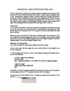
LIST OF FIGURES Figure 1 Frequency responses for the four classes of filters ...................................... 10 Figure 2 Data rate vs. Range for different wireless broadband standards [15]. ......... 11 Figure 3 N-section LC ladder circuit with element definitions for LP prototype. (a) Prototype beginning with a shunt element. (b) Prototype beginning with a series element [27]. ....................................................................................................... 13 Figure 4 T matrix for shunt and series impedances [28]............................................ 14 Figure 5 Circuit topology for capacitively coupled band pass filter [24]. ................. 17 Figure 6 Basic schematic diagram of microstrip MMR with 2 parallel-couple lines at the two ends of the network [16]. ....................................................................... 18 Figure 7 Layout and circuit diagram of MMR UWB band-pass filter. ...................... 19 Figure 8 Frequency response of 4th order UWB BPF [17] ........................................ 22 Figure 9 Human and GUI interaction [21]. ................................................................ 23 Figure 10 (a) Chaotic layout for GUI, (b) Ordered layout for GUI ........................... 24 Figure 11 GUI Development Environment (GUIDE) Layout Editor. ....................... 25 Figure 12 Gantt Chart and main project activities ..................................................... 27 Figure 13 Flow Chart used in programming the generalized Chebyshev and Butterworth filter responses. ............................................................................... 28 Figure 14 Flow Chart used in programming the Chebyshev and Butterworth filter responses from their respective circuit topologies. ............................................. 29 Figure 15 MCR and MatLab stand-alone applications .............................................. 30 Figure 16 Fragment code used to generate Frequency Response for Chebyshev Low Shunt Prototype................................................................................................... 32 Figure 17 The user interface of the developed application for microwave filter design. ................................................................................................................. 33 Figure 18 First Step: Select filter type and class ........................................................ 34 Figure 19 Second Step: Pop-up of the input dialog box, key in input data................ 35 Figure 20 Final Step: Display of Frequency Response of the selected filter. ............ 35
2
LIST OF ABBREVIATIONS FCC
: Federal Communications Commission
UWB : Ultra Wideband GUI
: Graphical User Interface
MatLab: Matrix Laboratory LPF
: Low Pass Filter
HPF
: High Pass Filter
BPF
: Band Pass Filter
BSF
: Band Stop Filter
RF
: Radio Frequency
Radar : Radio detection and ranging SoC
: System on Chip
EMI
: Electromagnetic interference
CAD : Computer Aided Design ADS
: Advanced Design Systems
HFSS : Ansoft High Frequency Structure Simulator GUIDE: Graphical User Interface Development Environment MCR : MatLab Compiler Runtime
Zo
: System impedance
UI
: User interface
LA
: Insertion Loss
LR
: Return Loss
N
: Order of the filter
L
: Inductor
C
: Capacitor
S
: Selectivity
s
: Stopband frequency
p
: Passband frequency
dB
: Decibel
Hz
: Hertz
GHz
: Gigahertz
3
CHAPTER 1 INTRODUCTION This chapter focuses mainly on presenting a brief background on microwave filters and graphical user interface. It states also the problem and the objectives of this research project.
1.1
Background For the last few decades, the world of high-speed computing devices and
systems have seen tremendous improvements. The latter technological advancement results from the endless contributions and efforts of researchers, scientists, system designers or industries from various engineering disciplines. Meanwhile, the demand for higher bandwidth systems and high performing devices that can handle multigigabits data transmission over communication media is also scaling rapidly. Consequently, this demand for high frequency and high bandwidth systems becomes the defining backbone of the emerging technologies such as high-speed system design, system on chip (SoC), radio frequency (RF) and microwave system design, telecommunication, wireless communication, satellite communication, radio detection and ranging (RADAR)... In designing these complex communication systems, it is crucial to ensure that the final product complies with the normal and targeted communication standards. Besides, it should also have the ability to handle signal interferences, to suppress electromagnetic interference (EMI) or the jittery interferences that might occurs during the data transmission; the system should also have a proper defined frequency spectrum for a given transmission. In the same perspective, microwave filters are used as two-port network to control the rejection of unwanted signal frequencies while allowing the desired signal frequencies to pass via a system [25]. These microwave filters are generally classified as Low-Pass (LP), High-Pass (HP), Band-Pass (BP) and Band-Stop. The
4
Band-Pass Filter can be broken down into narrow-band, wideband, ultra-wideband... Moreover, the latter type of BPF is still a novelty that has been seeing tremendous improvements. Different techniques and methods have been used to design advanced microwave filters that help in maximizing the performance and effectiveness of highspeed devices used in modern communication technology [1]. In the same perspective, the Federal Communications Committee (FCC) released ultra-wideband (UWB) technology (with a bandwidth ranging from 3.1GHz to 10.6 GHz), a novelty in radio technology for the advancement in communication, networking, radar systems, imaging systems, and positioning systems, and gave the official authorization for the use of UWB technology and its commercialization in 2002 [2], [3]. Ever since, this new proposed technology has revolutionized the world of communication and networking industries and it has helped them to provide better services to their respective customers; UWB technology has become one of the major focus point and the center of research in microwave filters [4]. In line with this technological development, it is important to provide freshmen (in the area of microwave filter design), designers, innovators and researchers with new tools and platforms such as computer aided design (CAD) or graphical user interface (GUI) that will help in simplifying their work while boosting their efficiency but cutting down the design time. A GUI, with reference to [5], is defined as a pictorial interface to a program. The graphical user interface can help its user to better perform the data analysis and interpretation via the extraction of important design parameters and the display of data in both numerical value and graphical or pictorial form. Throughout this research project, the emphasis will be put on the development of a graphical user interface (GUI) for the purpose of microwave filter design.
5
1.2
Problem statement With the cutting-edge technology of RF and microwave devices used in high
frequency applications, there are also powerful software and CAD tools available that help in the design of microwave filters or RF systems. In order to design RF systems or microwave filter for example, one or the combination of the following sophisticated platforms or simulation tools can be used for a computational design: Advance Design Systems (ADS) Agilent, Genesys RF and Microwave Design Software, Ansoft High Frequency Structure Simulator (HFSS), Microwave Office Design Suite, Cadence RF Design... However, designing microwave filters using these advanced tools requires a certain level of expertise, a strong programming skill or a very good knowledge in CAD. It was reported that in order to master the functionalities and maximize the usage of ADS design tools, an intensive training and extensive exposure to the software's environment is required [14]. This makes it difficult to help beginners such as sophomores, freshmen or any starter to understand the fundamentals and basic theory behind microwave filter design before transitioning them to be familiar with high level microwave design and synthesis tools. Similarly, due to time constraints in teaching microwave filters, as there are various materials to cover within a short period of time (approximately one semester), students are in need of software tools that will help them to easily practice computer simulations of microwave circuits for their homework and projects [30]. From professional designers' point of view, microwave filter design is a long and tiring journey towards reaching the final design and prototype. The process starts from the theoretical synthesis through schematic simulations to prototype fabrication and measurements. However, most of the time, the disagreement between the simulation and results occurs due to the unavailability of the synthesized theoretical values of the passive components in the market. Consequently, designers have to redo the simulations due to undesired output.
6
Moreover, references [14] and [30] suggest that the existing software tools for microwave filter design are costly. In addition, modern filter topologies are not yet integrated in these filter design tools. The proposed software tools in this project will incorporate both modern and conventional microwave filter topologies for industrial and educational applications. It will help users to get the 2D responses and their corresponding reactive element values from given specifications.
1.3
1.3.1
Objectives and Scope of Study
Objectives The main objective of this research project is to develop a stand-alone
graphical user interface (GUI) for microwave filter design. But most specifically, the intention is:
To review the mathematical modeling of microwave filtering
functions with their respective frequency responses.
To design and build a graphical user interface that can stand-alone and
help in the design of modern and conventional microwave filters.
To provide a low-cost and time-effective software tool for industrial
and educational applications.
To generate responses using both 2D response emulation and
simulation.
1.3.2
Scope of study The scope of study covers basically all the necessary approaches and steps
from the initial works to the final prototype resulting from this research project. The primary works start with the identification of the design parameters and requirements. Throughout this phase, the main task is to find the input parameters and the basic valid design criteria for each type and class of microwave filter that will be incorporated into the GUI. This phase is followed by the initial drafts of the
7
GUI layout design and its implementation in Graphical User Interface Development Environment (GUIDE). After a successful design of the GUI, the next major task will be the programming of the user interface (UI) functionalities such as save button, plot button, reset button, exit button... The secondary works will focus on testing, debugging and running the finalized prototype of the GUI.
8
CHAPTER 2 LITTERATURE REVIEW This chapter highlights briefly the technology and evolution of microwave systems; it covers also the key mathematical synthesis of microwave filtering functions, their respective transfer function using their scattering parameters (Sparameters), their ABCD matrix with relation to S-parameters through lumped elements and their design requirements. In addition, this section presents the previous works on GUI design and development for different applications and the fundamental design theory, principles or criteria behind GUI development using MATLAB software.
2.1
2.1.1
Theory of Microwave Filters
Basic Definition of terms relating to microwave filters Before proceeding further, it is crucial to review the fundamentals resulting
from the basic classification of microwave filters. In this generalized classification, each class of filter and its related concepts can be defined.
Low Pass Filter (LPF): As the name of this filter class states "Low
Pass", this filter passes only low frequency signal. That is to say, it allows signals with frequency from zero to cut-off frequency to pass and rejects all frequencies above its cut-off frequency.
High Pass Filter (HPF): It blocks all signal frequencies lower than cut-
off frequency while passing all signal frequencies higher than the cut-off frequency.
Band Pass Filter (BPF): This filter passes only signal frequencies that
are within its passband.
Band Stop Filter (BSF): BSF rejects all frequency signals within the
stopband and passes all signal frequencies that fall out of the stopband.
Stopband refers to the frequency band that is occupied by the
9
unwanted signal frequencies.
Passband refers to frequency band that is occupied by the desired
signal frequencies.
Transition band is the frequency band that allows the transition from
passband to stopband or vise versa.
Figure 1
2.1.2
Frequency responses for the four classes of filters
Overview of Ultra Wideband (UWB) Filter From the regulation issued by the FCC during the official release of UWB
technology, three fundamental types of UWB systems have been defined [3]:
Imaging systems.
Communication and measurement systems.
Vehicular and radar systems.
All UWB systems should be able to operate within the frequency band ranging from 3.1GHz to 10.6GHz. All signal being transmitted via UWB system should occupy a bandwidth (BW) of not less than 500MHz, the defined and selected signal BW is expected to be at least a quarter of the carrier or center frequency. With reference to this definition of UWB technology by the FCC, it is important to notice
10
that UWB systems and principally UWB filters are designed by incorporating both low pass filter (LPF) and high pass filter (HPF), the cascaded equivalence of LPF and HPF helps to create a dynamic UWB band-pass filter (BPF) [3], [13]. The technology of UWB systems have shown remarkable and excellent performance in its application for in wireless communication. It is able to transfer high data rate (100Mbps to 1Gbps) at the lowest power consumption compared to WiFi, IEEE 802.16, 2G or 3G but only for short distance (not more than 30 meters) applications. Figure (2) presents the difference between different wireless communication standards in of their respective data rates and supported ranges.
Figure 2
2.2
Data rate vs. Range for different wireless broadband standards [15].
Mathematical modeling of microwave filters Microwave filters are mostly synthesized using different filter responses:
maximally flat (Butterworth), equal ripple (Chebyshev), elliptic function, linear phase ... However, this project will mainly emphasize on Chebyshev and Butterworth filters as these two are the most commonly used attenuation characteristics microwave filters [25].
11
in
2.2.1
Maximally Flat or Butterworth Filters The generalized equation for Butterworth low pass prototype is specified by
[25],[24]: S12
1
2
(2.1)
1 2N
where
, with c as the cut-off frequency and as frequency variable. N is c
the filter order, and it is related to the selectivity (S), the return loss (LR) and the insertion loss (LA) by: N
LA LR 20 log10 S
with S
(2.2)
s 1 p
(2.3)
where s refers to the stopband frequency and p the passband frequency. LR and LA are in dB. The transfer function related to S11 can be expressed by using the following relationship: S12 S11 1 2
2
2.2.1.1
(2.4)
Element values for Butterworth filter
The N (where N is the number of reactive elements) element values for a twoport network ended at both ends with a resistor using maximally flat filter characteristics can be computed as follow [25],[27]: go g N 1 1
(2.5)
2k 1 g k 2sin ; where k 1, 2,3,..., N 2N
(2.6)
The related reactive elements for both series and shunt N-section LC ladder network are obtained through: Lk
Zo gk
(Series elements)
(2.7)
Ck
gk (Shunt elements) Z oc
(2.8)
c
12
where k 1, 2,3,..., N The reactive elements (L and C) alternate depending on the ladder type (shunt or series) as shown in figure (3). Z o is the system impedance.
Figure 3 N-section LC ladder circuit with element definitions for LP prototype. (a) Prototype beginning with a shunt element. (b) Prototype beginning with a series element [27].
2.2.1.2
ABCD parameters and S-parameters
The ABCD parameters of a network are defined by the transfer matrix which is the result of a relationship between the input voltage and current to the output voltage and current [24].
T
A
B
C
D
(2.9)
The transfer matrix for series impedance and shunt impedance network is defined in Figure (4).
13
Figure 4
T matrix for shunt and series impedances [28]
For cascaded network like the N-section LC ladder network shown in figure (3), the total transfer matrix for both circuits can be obtained by matrix multiplication from the T matrix of the first reactive element till the T matrix of the last element. By using the relationship that helps in converting the ABCD parameters to Sparameters [28], one can extract the expression of each S-parameter. Z o A B Z o2C Z o D 2Z o AD BC S11 S12 1 (2.10) S S Z A B Z 2C Z D 2Z o Z o A B Z o2C Z o D 21 22 o o o
S21
2 A B / Z o Z oC D
S21
(2.11)
4
2
A B / Z o Z oC D
(2.12)
2
Due to the symmetrical nature of maximally flat low pass prototype using its element values, deductively:
S12 S21 2
2
4 A B / Z o Z oC D
(2.13)
2
Similarly, S11 and S 22 can be expressed in term of ABCD parameters.
2.2.2
Equal Ripple or Chebyshev Filters For Chebyshev response, the generalized filtering equation for low pass
prototype is defined as [25]:
14
S12 2
1 1 TN ( ) 2
(2.14)
2
1 cos N cos , 1 where TN ( ) cosh N cosh 1 , 1
c
(2.15)
(2.16)
100.1L 1
(2.17)
Ar
where c referring to its cu-off frequency, the frequency variable and is the ripple level. The filter order (N) of this filter response is related to its insertion loss (LA), return loss (LR) and selectivity (S) by:
N
LA LR 6
20 log10 S S 2 1
(2.18)
where S is defined by equation (2.3). The passband ripple ( L Ar ) can be computed by using the following mathematical expressions:
LAr 10log10 (1 2 )
(2.19)
where refers to the reflection coefficient and it is related to the return loss (LR) by:
10( RL /20) 2.2.2.1
(2.20)
Element values for Chebyshev filter
For low pass prototype using Chebyshev response, the reactive elements of the N-section LC ladder circuit portrayed in figure (3) can be obtained through these equations [25]:
LAr 17.37
ln coth
2N
sin
(2.21 - 2.24)
2k 1 ak sin ; k 1, 2,3,..., N 2 k k bk 2 sin 2 ; k 1, 2,3,..., N N
15
Therefore, the element values can be computed using:
go 1 g1
2a1
gk
4ak 1ak ; k 2,3,..., N bk 1 g k 1
(2.25 - 2.28)
for N Odd 1 g N 1 2 coth for N Odd 4 where L Ar is the passband ripple (dB). The associated reactive elements are similar to those described by equations (2.7) and (2.8); and the resulting ABCD matrix and S-parameters can be computed using equations listed in section (2.2.1.2).
2.2.3
Low Pass to High Pass, Band Pass or Band Stop Transformation. In microwave filter design, with the use of filter prototype transformation, it is
possible to convert a low pass prototype to either high pass, band pass or band stop prototype. This transformation is done through a frequency substitution [24],[25].
For low pass to high pass transformation, frequency substitution is
done as follow:
c
(2.29) When converting a low pass to band pass prototype, the low pass
circuit undergoes the following frequency substitution:
o
o
2 1
o
(2.30)
and o 1 2
(2.31 - 2.32)
where o is the mid-band frequency and is the bandwidth scaling factor.
The last transformation is the conversion of a low pass prototype to
band pass prototype which is achieved via this frequency substitution:
16
o
2 1
1
(2.33)
o o
, o 1 2
(2.34 - 2.35)
where o referring to the mid-band frequency and the bandwidth scaling factor.
2.2.4
Extra classes of Chebyshev Band Pass Filter
2.2.4.1
Capacitively coupled Chebyshev Band Pass filter
The circuit topology for this filter class is shown figure (5).
Figure 5
Circuit topology for capacitively coupled band pass filter [24].
With reference to [24], the reactive elements of this topology is derived using the following equations:
1 1 sinh 1 N
sinh Cr
K
2r 1 sin ; 2N 2
r , r 1
r N
r 1, 2,3,..., N
(2.36 - 2.38)
2
2 sin
where the ripple level ( ) and the order of the filter (N) are described by equations (2.17) and (2.18) respectively. By parameter values described in the above equations, the element values can be computed.
17
C01 C N , N 1 Cr ,r 1 C11 C NN
K r ,r 1
o
Cr
o
1
o 1 ;
r 1, 2, 23,..., N 1
1 C12 o
(2.39 - 2.44)
1 C N 1, N o o
Crr Lrr
CN
Cr
o
Cr 1,r Cr ,r 1 ;
r 2, 23,..., N 1
1 C r o
The filter order (N), the mid-band frequency ( o ) and the bandwidth scaling factor ( ) are computed using equations (2.17), (2.34) and (2.33) respectively. 2.2.4.2
Mathematical modeling of Chebyshev Ultra Wideband (UWB) BP Filter
Throughout the gradual evolution of UWB technology, different design techniques, models and structures for microwave filters have been used to build prototypes that comply fully with the standards of the UWB systems [16]. Among these structures that exhibit reliably the qualitative and quantitative behaviour of a successful ultra wideband system, the structure involving microstrip made up of a microstrip multi-mode resonator (MMR) and a parallel-coupled line at each end of the network. The basic configuration of this category of microstrip is portrayed in figure (6).
Figure 6 Basic schematic diagram of microstrip MMR with 2 parallelcouple lines at the two ends of the network [16].
18
Further improvements on the microstrip MMR based UWB systems in order to achieve better UWB passband behaviour have been done. Figure (7) depicts the layout of the MMR UWB band-pass filter (BPF) and its equivalent circuit diagram.
Figure 7
Layout and circuit diagram of MMR UWB band-pass filter.
Where l1 refers to the coupling length, w1 and w2 the strip widths, S and g refer to the slot width and the wavelength respectively. Z o defines the characteristic impedance while Z oe and Z od are the related even-mode and odd-mode characteristic impedances of microstrip MMR based UWB BPF. The mathematical modeling of UWB BPFs, that is presented in the following sections of this sub-chapter and adapted from reference [13], [17], was derived using the above described topology. 2.2.4.2.1 Fourth order UWB BPF The filtering function , T ,for fourth order UWB band-pass filter is defined as the Chebyshev function by:
T
A cos 4 B cos 2 C
(2.45)
sin
A reciprocal relationship can be established between the electrical length , the center frequency f c (with f c ( f c ( HPF ) f c ( LPF ) ) / 2 ) and the frequency f of the filter. 19
2
f fc
(2.46)
Equation (1) presents the characteristic of a Chebyshev polynomial. For equal ripples in Chebyshev polynomial T with an inverse dependence in term of the filter frequency f , it is crucial to normalize T . The restructured mathematical model of T is: T T T ( norm )
Here, norm
(2.47)
, T and refers to the factor of the normalization of T 2
and the ripple factor respectively. The ripple factor or ripple level ( ) is computed using equation (2.16). T is given by:
T
cos 4 cos 2
(2.48)
sin
where A
T ( norm )
(2.49)
B A
(2.50)
C A
(2.51)
where norm , B
, T ( norm ) , therefore the expression of A, B and C become: A 2
and C . and components can be computed from their
relationship with the bandwidth ( BW f c ( HPF ) f c ( LPF ) ) 2 4 0 and 1 0 inequalities.
20
while complying with
3 BW cos 4 2
BW
1
2
1 4 3 3
(2.52)
BW
sin 2 1 cos 4 2 2
(2.53)
Nota Bene: The bandwidth (BW) value in GHz should be converted to its equivalent value in radian using equation (2.44) prior to the computation of and expressed in equation (2.50) and (2.51). The following table summarizes the values of for different return losses.
Table 1
Return Loss (LR) and its equivalent Ripple Factor or Ripple Level
Return Loss (RL) (dB) 1 2 3 4 5 6 7 8 9 10 11 12 13 14 15 16 17 18 19 20
Reflection coefficient 0.8913 0.7943 0.7079 0.6310 0.5623 0.5012 0.4467 0.3981 0.3548 0.3162 0.2818 0.2512 0.2239 0.1995 0.1778 0.1585 0.1413 0.1259 0.1122 0.1000
Passband Ripple (dB) 6.8683 4.3292 3.0206 2.2048 1.6509 1.2563 0.9665 0.7494 0.5844 0.4576 0.3594 0.2830 0.2233 0.1764 0.1396 0.1105 0.0875 0.0694 0.0550 0.0436
Ripple Factor 1.9652 1.3076 1.0024 0.8133 0.6801 0.5792 0.4993 0.4340 0.3795 0.3333 0.2937 0.2595 0.2297 0.2036 0.1807 0.1605 0.1427 0.1269 0.1129 0.1005
The transfer functions for UWB BPF are related to T by the following equations; their expressions in term of A and T can also be derived using equation (2.45) and (2.47). Therefore:
S11
2
2
2 T 2 ( ) T ( ) S11 2 2 2 1 T ( ) A T ( )
21
(2.54)
S 21 2
1 1 2 S 21 2 2 1 T 2 ( ) 1 A T ( )
(2.53)
From these equations, the dB expression of S11 and S 21 for graphical 2
2
analysis of their respective frequency response can be computed accordingly. S11
2
S 21
( dB)
2 ( dB)
2 20 log 10 T 10 log 10 A2 T
(2.54)
2 10 log 10 1 A2 T
(2.55)
The graphical form of the S11 and S 21 are portrayed in the following 2
2
figure.
Figure 8
2.3
Frequency response of 4th order UWB BPF [17]
Graphical User Interface (GUI) Design GUI plays an important role as the medium between the user and a computer
program. The user interface provides the user with an environment integrated with interactive controls, commands, feedbacks ... with a predictive response. A simple example of human and computer interface is described in figure (9).
22
Figure 9
2.3.1
Human and GUI interaction [21].
Fundamental Principles for GUI design According to a recent study conducted at the Xi’an University of science and
technology, a number of design considerations and criteria such as dynamism, consistency and attractive visual appearance of the user interface, its layout and functions have been analyzed with respect to consumer's need, desire, taste and likes [20]. This important study was done using Kansei Engineering (KE), an engineering discipline with emphasis on implicit satisfaction and pleasure of consumer prior to product design, highlights the importance of the interaction between humans and the user interface and shows how the consideration of human's cognitive psychology and anthropology on the artificial intelligence of the GUI can help to boost the product's market. According Martin [22], there are three fundamental design factors for a successful and information-oriented GUI: the development factors, the visibility factors and the acceptance factors. Similar to the study done by Sun [20], these three factors covers the basics requirements that are deemed fit in term of their compliance with human's anthropological and psychological perception. Moreover, Martin [22] has provided some guiding principles to be followed when designing a graphical user interface. For a successful GUI design, it is imperative to organize the layout design properly, to economize the window of the interface and to make a user friendly GUI. In figure (10) bellow are examples of a "good layout" and "bad layout" structures of a GUI.
23
Figure 10
2.3.2
(a) Chaotic layout for GUI, (b) Ordered layout for GUI
MATLAB GUI MATLAB GUI, like other graphical user interfaces, is to help people without a
good command of programming language to be able to interact with the machine without the need to master it [23].
Marchand and Holland [23] continue on
suggesting and defining the design stages involved in the development of a GUI using MATLAB software. Prior to the GUI design, the developer should make a proper analysis by identifying the end user and defining the user guide. This stage should be followed by the layout design of the user interface based on the analysis done during the first design stage and KE design considerations. Then, the designer should draft and sketch skillfully its layout design on a piece of paper before proceeding to the actual design and construction of the GUI. When designing GUI using MATLAB, Marchand and Holland [23] present two different approaches: GUI Development Environment (GUIDE) technique and Programmatic approach.
In Low-Level MATLAB GUI programming approach, the developer
program the GUI using M-File, all the graphic elements of the interface are also programmed along with the GUI. In this approach, the designer should define all the functions or Callbacks involved.
24
In High-Level GUI Development Environment (GUIDE) approach,
compared to the programmatic approach which involve a lot of "hand-programming" for the creation of the GUI, this new technique uses the embedded feature (GUIDE) of MATLAB to create the complete GUI which can be saved as FIG-file. However, once the GUI is designed, all the Callback functions need to be programmed accordingly. The complete GUI layout editor shown in figure (11) is obtained by entering the guide at the command prompt.
Figure 11
GUI Development Environment (GUIDE) Layout Editor [29].
25
CHAPTER 3 METHODOLOGY This chapter focuses on the methodology that will be used in the conduct of this research project. It comprises of research methodology, project activities, key milestones, Gant Chart and tools used.
3.1
Research Methodology Prior to stepping into the design phase of the user interface, a deeper
exploration, research and review were conducted on the fundamental theories of microwave filters. The primary research was intended to help in grasping the behavior of each filter type and class; their respective frequency response characteristic and the identification of the major key elements needed for the design of a given class of filter. Moreover, some of the key factors, guiding principles and procedures for the design of a dynamic, user-friendly and marketable graphical user interface have been highlighted. In order to carry out this project, which is to develop a stand-alone GUI for microwave filter design, the high-level GUI development environment (GUIDE) approach will be used to design the layout of the graphical user interface. The related M-file will then be used to program all the callback functions of the user interface. Moreover, all the filtering function, parameters, coefficients, frequency responses ... of the filter derived in section 2.2 will be used to develop a proper algorithm to be integrated with the designed GUI. The finalized design will be tested for consistency, debugged for any designed error that might occur and submitted for educational and industrial use.
26
Figure 12
3.2
Gantt Chart and main project activities
Microwave Filters Programming The adopted algorithm, which is used to program the filtering functions,
frequency responses and the related design parameters for microwave filter, is presented in the form of flow chart in figure (13.1). This flow chart shows also how the graphical user interface will operate. The user will need to select the desired type and class of microwave filter on the user interface. The GUI will take the valid input parameters (such as return loss, insertion loss, pass-band or stop-band frequencies, filter bandwidth ...) from the user. The next task of the GUI is to proceed to displaying the graphs and important data needed by the user on the user interface.
27
Generation frequency responses of of Chebyshev or Butterworth Filter START
Select Filter Type (Chebyshev or Butterworth)
Select Filter Class (LP,HP,BP,BS, UWB BPF)
NO From Filter’s Generalized Equation?
Using Circuit Topology
YES
Enter Input Parameters
FAILED Check Design Criteria
PASSED Perform all related Computations
Report Error
Display the Response from Generalized Equation
END
. Figure 13
Flow Chart used in programming the generalized Chebyshev and Butterworth filter responses.
28
Frequency Response from Circuit Topology Specify Shunt, Series Prototype, Capacitively coupled BPF
FAILED Check Design requirements
PASSED Generate Elements Values and Compute respective impedances and admittances
Report Error
Compute ABCD matrix, |S11|^2 and |S12|^2
Plot the related Response
END
Figure 14
3.3
Flow Chart used in programming the Chebyshev and Butterworth filter responses from their respective circuit topologies.
Stand-alone GUI and MatLab Compiler Runtime (MCR) The developed GUI (in MatLab) can be deployed and converted into an
executable (.exe) file. The deployed MatLab GUI project can successfully run on
29
computers with no MatLab software installed, however the stand-alone GUI can run on those computers with the help of MCR. The MCR is a set of libraries that help to run MatLab applications or components on computers with no MatLab installed, it is free to use, to distribute and it can be downloaded via MathWorks website. This MatLab Compiler Runtime is available for Windows, Linux and Mac operating systems.
Figure 15
MCR and MatLab stand-alone applications
30
CHAPTER 4 RESULTS AND DISCUSSION This chapter is objectively intended to provide the results of the research project. It presents a concise information on the GUI's artificial intelligence and user interface controls' operations. An ample discussion is also made on the subject matter.
4.1
Programming approach of the GUI and the Transfer Functions. Structured programming approach was adopted for the design of the GUI, to
write its related program codes for both transfer functions and user interface controls. Structured programming approach is the most commonly used approach in software development. By making use of the control structures (sequence, selection and repetition) that this approach provides, the application will be easier to debug, modify and its program code will be easier to understand.
4.1.1
Coding the Transfer Functions The MatLab M-file has been used to program the transfer functions of all the
classes of filters that are incorporated in the final prototype. The integrated microwave filters are listed as in table (2).
31
Table 2
Chebyshev and Butterworth Filters incorporated into the GUI.
Total number of responses
Filter Types
Filter Classes LPF HPF
15
Chebyshev
BPF
Filter Responses generated using Chebyshev Generalized Equations ABCD Matrix
BSF LPF HPF 12
Butterworth
BPF BSF
Butterworth Generalized Equations ABCD Matrix
In total, the GUI will enable its users to design microwave filters for four filter classes using both Chebyshev and Butterworth responses to generate up to twenty seven (27) responses using different techniques and approaches. More importantly, the programmatic approach that has been adopted in handling each and every filter response differs with reference to each filter's prototype, topology, parameters, characteristics, definition and complexity. The following figure provides a fragment of the code used to generate Chebyshev low pass shunt prototype.
Figure 16
Fragment code used to generate Frequency Response for Chebyshev Low Pass Shunt Prototype.
32
4.1.2
Design and implementation of the GUI in MatLab The application has been designed in MatLab using its built-in tool (the
Graphical User Interface Development Environment or GUIDE). The development of this GUI is characterized by the simplicity of the interface for the users to be easily familiar with it. It is intended to help users to perform a straight forward design by selecting the type and class of the filter, the next step will be just to key in the input parameters in order to obtain advanced graphical displays and numerical data for further analysis. The finalized user interface of the stand-alone application is portrayed in figure (17).
Figure 17
The user interface of the developed application for microwave filter design.
The related MatLab M-file has been used to write the program codes relating to the user interface controls (help dialog box, input dialog box, radio buttons for filter classes, exit button, save button...) of the GUI. The manipulation of this user interface controls helps in creating a dynamic artificial intelligence for this GUI that will make the user aware before making any unwanted, undesired or involuntary decision. The GUI can also inform the user through a pop-up dialog box in case the input parameters violate the design requirement. In addition, the four classes of filters (LPF,HPF,BPF and BSF) for both Chebyshev and Butterworth filter type can be designed only one at a time. That is to 33
say, if a radio button of Chebyshev low pass is selected, all the remaining buttons will be automatically inactive. The finalized prototype is deployed and converted into an executable (.exe) format. The converted format can run as a stand-alone application by using the set of libraries provided in MatLab Compiler Runtime (MCR). 4.1.2.1
Demonstration of microwave filter design using the GUI
4.1.2.1.1 Chebyshev Low Pass Filter In order to proceed to the design of Chebyshev LP filter, the user has three options (Chebyshev LP Generalized Equation, Chebyshev LP Shunt Prototype and Chebyshev Series Prototype) through the pop-up menu next to LPF under Chebyshev filter. The final step to displaying the response of the desired filter is to hit the plot button, a pop-up of input dialog box will be automatically displayed for the user to key in his/her data followed by a single click on the "OK" button of the pop-up input dialog box. A step by step illustration of the situation described above is shown in the following figures.
Figure 18
First Step: Select filter type and class
After hitting on the "Plot Now" button, this input dialog box will pop-up, the user will need to enter the input data in their respective field. The user will be 34
required also to hit the OK button in order to proceed to the display of the filter's frequency response.
Figure 19
Figure 20
Second Step: Pop-up of the input dialog box, key in input data.
Final Step: Display of Frequency Response of the selected filter.
This Print Screen of the GUI shows the frequency response of the Chebyshev low pass filter with reference to the user's selection of filter type, filter class and input parameters using its generalized equation. The order of the filter is computed using the input data and displayed in the field of "Filter Order" at the left side of the
35
GUI; the selectivity and the ripple level are also displayed in their respective fields. 4.1.2.1.2 Chebyshev High Pass Filter For the case of high-pass filter, responses can be generated. An example of 7th order Chebyshev HPF Series prototype is illustrated in the figures below. The first step is the same for all filter types and classes and it is similar to situation described in figure (18).
Figure 21
Figure 22
Second Step: Input data for Chebyshev HP Series Prototype.
Final Step: Display of Frequency Response of Chebyshev HP Series 36
Prototype.
In figure (22), the corresponding values of reactive elements and the impedances (for both source and load) are displayed in their respective field. They are all displayed in array form. The user will need to identify the individual elements using this analogy: L (nH)
= [6.567 3.416 3.416 6.567] =
L1 , L3 , L5 , L7
Thus L1 = 6.567 nH, L3 = 3.416 nH, L5 = 3.416 nH and L7 = 6.567 nH. C (pF)
=
[1.846 1.636 1.846]
=
C2 , C4 , C6
Hence C 2 = 1.846 pF, C4 = 1.636 pF and C6 =1.846 pF. And Z = [50 50] = [ Z s , Z L ], thus Z s = 50 and Z L = 50 4.1.2.1.3
Chebyshev Band Pass Filter
As an illustration for BPF, the response and the important parameters can be obtained for capacitively coupled BPF. The following figures exemplify capactively coupled circuit topologies.
Figure 23
Second Step: Input data for Chebyshev Capacitively coupled BPF.
37
Figure 24
Final Step: Frequency Response of Chebyshev HP Series Prototype.
From figure (24), the impedances for both source and load are Z s = 50 and Z L = 50 . The reactive elements are also portrayed in their respective field. By
identification: C (pF) = [0.7303 2.067 0.2101 6.71 0.251 6.71 0.2101 2.067 0.7303] = C01, C11, C12 , C22 , C23 , C33 , C34 , C44 , C45 Therefore
C01 C45 0.7303 pF C11 C44 2.067 pF C12 C34 0.2101 pF C22 C33 6.71 pF C23 0.251 pF. L (nH) = [8.527 3.532 3.532 8.527] = L11, L22 , L33 , L44 Thus L11 = L44 = 8.527 nH and L22 = L33 = 3.532 nH These reactive element values, source and load impedances can be used to construct the corresponding microwave circuit for the filter.
It is also important to illustrate the case of UWB band-pass filter as it is one of
38
the latest microwave filter topology that has been integrated for the first time and only in this filter design tool. The illustration for this case is presented as follow:
Figure 25
Second Step: Input data for Chebyshev Capacitively coupled BPF.
Figure 26
Final Step: Frequency Response of 4th order UWB BPF.
39
4.1.2.1.4
Maximally Flat Band Pass Filter
Likewise, when the user intend to design microwave filter using the maximally flat response, the procedures are almost the same with equal-ripple response demonstrations. For example, to design a band-stop filter using Butterworth response, the following steps are followed (assuming that the filter type and class were selected).
Figure 27
Figure 28
Second Step: Input data for Butterworth BSF.
Final Step: Frequency Response of Maximally flat BSF.
40
The individual reactive element values for the linear microwave circuit can be obtained by using this following identification.
L (nH) = [30.48 3.045 6.536 6.313 4.307 7.89 4.013 7.352 5.015 4.844 10.4 1.039] =
L1 , L2 , L3 , L4 , L5 , L6 , L7 , L8 , L9 , L10 , L11, L12
Thus L1 = 30.48 nH, L2 = 3.045 nH, L3 = 6.536 nH, L4 = 6.313 nH, L5 = 4.307 nH, L6 = 7.89 nH, L7 = 4.013 nH, L8 = 7.352 nH,
L9 = 5.015 nH, L10 = 4.844 nH, L11 = 10.4 nH and L12 = 1.039 nH. C(pF) = [0.4155 4.159 1.938 2.006 2.94 1.605 3.156 1.723 2.525 2.614 1.218 12.19] =
C1 , C2 , C3 , C4 , C5 , C6 , C7 , C8 , C9 , C10 , C11, C12
Hence C1 = 0.4155 pF, C2 = 4.159 pF, C3 = 1.938 pF, C4 = 2.006 pF, C5 = 2.94 pF, C6 = 1.605 pF, C7 = 3.156 pF, C8 = 1.723 pF,
C9 = 2.525 pF, C10 = 2.614 pF, C11 = 1.218 pF and C12 = 12.19 pF. And Z = [50 50] = [ Z s , Z L ], thus Z s = 50 and Z L = 50 4.1.2.2
Hallmarks of the graphical user interface
The major feature of this GUI is its simplicity. It is a straightforward software tool for microwave filter design that can help students and learners to grasp the concept of microwave engineering. In addition, it takes less than a minute to display an impeccable filter response that can be the basis and the framework for a scientific and technical discussion. The key characteristics and features of the proposed GUI are presented in the table below.
41
Table 3
Major features of the GUI and its comparison with the existing design tools.
Features Conventional filter topologies
Classical tools
Proposed tool
Modern filter topology
2-D response simulation
2-D response emulation
Easy to use, good for sophomores
Stand-alone capability
42
CHAPTER 5 CONCLUSION & RECOMMENDATIONS The developed graphical user interface for microwave filter design can successfully run on both computers with MatLab installed and on PCs with no MatLab software. For the latter case, the stand-alone GUI can run with the help of MatLab Compiler Runtime (MCR) that carries the necessary library required to run stand-alone MatLab applications. The GUI environment is easier for users to comprehend and familiarize themselves with. This modest GUI design can help the end-users to create impeccable and professional microwave filters even if they do not have a high level of expertise in the area of filter design tools, simulator or advanced design systems. The proposed graphical user interface is integrated with both modern and conventional microwave filter topologies. This software tool can significantly help in reducing the training time and cost. It is the right and appropriate software tools for microwave education for both industries and educational institutions. For future research works in this area, the graphical user interface can be developed using another approach. This approach can be directed to the use of object oriented programming such as java GUI programming, QT5 or VB.Net to create a dynamic synthesis tool for microwave filter design. From this approach, the possibility of integrating circuits and systems (such as schematic diagrams, functional blocks, nonlinear components, symbolic variables ...) can also be explored.
43
REFERENCES [1]
[2] [3] [4] [5] [6]
[7] [8]
[9]
[10] [11] [12]
[13]
[14] [15] [16] [17] [18] [19]
[20]
I. Hunter and A. Abunjaileh, "Recent Advances in Microwave Filters," in Art of Miniaturizing RF and Microwave Passive Components, 2008. IMWS 2008. IEEE MTT-S International Microwave Workshop Series on, 2008, pp. 13-14. FCC, "Revision of part 15 of the Commission's rules regarding Ultra Wideband transmission system," FCC, Washington, D.C., Tech. Rep. ET-Docket 98-153 FCC02-48, Apr. 2002. Y. Liuqing and G. B. Giannakis, "Ultra-wideband communications: an idea whose time has come," Signal Processing Magazine, IEEE, vol. 21, pp. 26-54, 2004. G. R. Aiello and G. D. Rogerson, "Ultra-wideband wireless systems," Microwave Magazine, IEEE, vol. 4, pp. 36-47, 2003. A. I. Abdulla, R. Yousef, and A. Al Ameri, "Introduction to Graphical User Interface (GUI) MATLAB 13® 6.5," UAE University, 2001. W.-J. Lin, I.-T. Tang, D.-B. Lin, C.-M. Li, M.-Y. Chiu, and M.-P. Houng, "A Compact Ultrawideband Bandpass Filter with Low Insertion Loss Using Stub Circuits with Defected Ground Structure," 2008. C. G. T. a. K. M. Lum, "Ultra-wideband Bandpass Filter Using Symmetrical Step-impedance Resonators," in PIERS Proceedings, Moscow, Russia, 2012. C. Yao, W. Zhang, L. Han, and R. Ma, "A New Type of Miniature Ultra-Wideband BandPass Filter with Coplanar Waveguide Fed," International Journal of Infrared and Millimeter Waves, vol. 28, pp. 859-863, 2007. Z.-C. Hao, J.-S. Hong, J. P. Parry, and D. P. Hand, "Ultra-wideband bandpass filter with multiple notch bands using nonuniform periodical slotted ground structure," Microwave Theory and Techniques, IEEE Transactions on, vol. 57, pp. 3080-3088, 2009. M. Nath, "A Compact UWB filter for Wireless communication," IJSRET, vol. 1, p. 7, May 2012 2012. H. Ishida and K. Araki, "Design and analysis of UWB band pass filter," in Wireless Communication Technology, 2003. IEEE Topical Conference on, 2003, pp. 457-458. L. Rui, S. Sheng, and Z. Lei, "Synthesis Design of Ultra-Wideband Bandpass Filters With Designable Transmission Poles," Microwave and Wireless Components Letters, IEEE, vol. 19, pp. 284-286, 2009. S. Khalid, W. Wong Peng, and C. Lee Yen, "Synthesis and design of four pole ultra-wide band (UWB) bandpass filter (BPF) employing multi-mode resonators (MMR)," in Microwave Symposium Digest (MTT), 2012 IEEE MTT-S International, 2012, pp. 1-3. C. Alabaster, "COMPARISON OF SOFTWARE TOOLS FOR THE DESIGN OF MICROWAVE COMPONENTS." J. Bergervoet, et all. (2005, Design Challenges for Ultra-Wide Band Radio. Available: http://www.ewh.ieee.org/r6/scv/ssc/Jun1605.pdf S. Y. Huang and Y. H. Lee, "Development of ultra-wideband (UWB) filters," General Assembly of the International Union of Radio Science, pp. 7-16, 2008. S. Khalid, W. Wong Peng, " A novel synthesis procedure for UWB bandpass filters,", Universiti Teknologgi PETRONAS, 2004. M. Microwave. Return Loss to VSWR Conversion Table. Available: http://www.markimicrowave.com/menus/data/return%20loss%20to%20vswr.pdf C. Chun-Ping, M. Zhewang, and T. Anada, "Synthesis of UWB bandpass filter by multistage of one-wavelength commensurate SIRs," in Microwave and Millimeter Wave Technology, 2008. ICMMT 2008. International Conference on, 2008, pp. 1247-1250. S. Ying-li, "The study of man-machine interface design based on Kansei engineering and with the center on users," in Industrial Engineering and Engineering Management (IE&EM), 2011 IEEE 18Th International Conference on, 2011, pp. 650-652.
[21]
A. Knob. Human Machine Interface (Lecture notes) HEIG-VD (2005)
[22]
S. Martin. (1995), Designing Effective User Interfaces. Available: http://web.cs.wpi.edu/~matt/courses/cs563/talks/smartin/int_design.html
[23]
P. Marchand, Holland, T, Graphics and GUI with MATLAB: Chapman & Hall/CRC, 2002.
[24] [25]
I. C. Hunter, Theory and Design of Microwave Filters. London, UK: lEE, 200 1, pp. 38-43. G. Matthaei, L. Young and E.M.T. Jonesa, Microwave Filters,Impedance-Matching Network,and Coupling Structures: Artech House, 1980
44
[26]
Wisc-Online, Ideal filters. Avaialabled at http://www.wisc-online.com/Objects/ViewObject.aspx?ID=ACE2603
[27]
D. M. Pozar, Microwave Engineering: John Wiley & Sons, 4th Ed.,2012
[28]
S. I. Syed, Network Parameters. Class notes, School of electrical & electronic engineering, Universiti Sains Malaysia of Penang. Available at http://ee.eng.usm.my/eeacad/mandeep/kursus%20RF/Network%20Parameters.ppt
[29]
The Mathworks, Creating Graphics User Interfaces,Version https://maxwell.ict.griffith.edu.au/spl/matlab-page/buildgui.pdf
[30]
V.T. Dejan and P. Milka, Software Tools for Research and Education. Available at http://www.mtt-serbia.org.rs/microwave_review/pdf/Vol12No2-09-DTosic.pdf
45
1.
Available
at
APPENDICES APPENDIX A : COMPLETE GUI CODE % |=======================================================================| % | The following codes help in building the GUI for the generation of
|
% | Chebyshev (Equi-ripple) and Butterworth (Maximally flate) LP, HP, BP
|
% |or BS responses for any order. These codes were developed and completed| % |on 10th December 2013 by DJENGOMEMGOTO GERARD, for the purpose of Final| % |Year Project under the supervision of Dr Wong Peng Wen.
|
% | Version 1.0 , December 2013 Universiti Teknologi PETRONAS.
|
% | © Copyright 2013, Universiti Teknologi PETRONAS
|
% |=======================================================================| function varargout = MW_Filter_FYP2(varargin) %MW_FILTER_FYP2 M-file for MW_Filter_FYP2.fig % Last Modified by GUIDE v2.5 10-Dec-2013 11:35:30 % Begin initialization code - DO NOT EDIT gui_Singleton = 1; gui_State = struct('gui_Name', 'gui_Singleton',
mfilename, ... gui_Singleton, ...
'gui_OpeningFcn', @MW_Filter_FYP2_OpeningFcn, ... 'gui_OutputFcn',
@MW_Filter_FYP2_OutputFcn, ...
'gui_LayoutFcn',
[], ...
'gui_Callback',
[]);
if nargin && ischar(varargin{1}) gui_State.gui_Callback = str2func(varargin{1}); end if nargout [varargout{1:nargout}] = gui_mainfcn(gui_State, varargin{:}); else gui_mainfcn(gui_State, varargin{:}); end % End initialization code - DO NOT EDIT % --- Executes just before MW_Filter_FYP2 is made visible. function MW_Filter_FYP2_OpeningFcn(hObject, eventdata, handles, varargin) % This function has no output args, see OutputFcn. % hObject
handle to figure
% eventdata
reserved - to be defined in a future version of MATLAB
% handles
structure with handles and user data (see GUIDATA)
% varargin
unrecognized PropertyName/PropertyValue pairs from the
%
command line (see VARARGIN)
% Choose default command line output for MW_Filter_FYP2 handles.output = hObject; % Update handles structure guidata(hObject, handles); % --- Outputs from this function are returned to the command line. function varargout = MW_Filter_FYP2_OutputFcn(hObject, eventdata, handles) % varargout
cell array for returning output args (see VARARGOUT);
% Get default command line output from handles structure varargout{1} = handles.output;
% --- Executes during object creation, after setting all properties. function pushbuton_plot_CreateFcn(hObject, eventdata, handles) % hObject
handle to pushbuton_plot (see GCBO)
% eventdata
reserved - to be defined in a future version of MATLAB
% handles
empty - handles not created until after all CreateFcns called
46
% --- Executes on button press in pushbutton_resetAll. function pushbutton_resetAll_Callback(hObject, eventdata, handles) reset_button =questdlg('Are you sure you want to clear all data? Make sure to save your current data.','Clear All','Yes','No','No'); switch reset_button % if user anser is yes, then reset all data and figure. case 'Yes' set(handles.InductorValues1,'String','');
% to clear the field for Inductor values
set(handles.CapacitorValues1,'String','');
% to clear the field for capacitor values
set(handles.ImpedanceValues1,'String','');
% to clear the field for imepdance values
set(handles.edit14_selectivity,'String','');
% to clear the field for selectivity
set(handles.edit15_ripple,'String','');
% to clear the field for ripple level
set(handles.FilterOrder,'String','');
% to clear the field for filter order
legend('hide');
%To clear the legend
% Clear all the previous stored variables in the workspace clear all; % Clear all the lines currently in the MatLab Command Window clc; % this command clears the current plotted figure in the axe window. cla; % Otherwise, return to the current window with its current data and % figure case 'No' return end % --- Executes on button press in pushbutton_help. function pushbutton_help_Callback(hObject, eventdata, handles) %Providing help to users helpdlg('To design your microwave filter, follow these three steps: 1) Select the filter type and class using the radio buttons at the top left corner.
2) Using your mouse, hit the "Plot Now" button.
3) Key in your input data
in the pop-up input dialog box. Click on "ON" button of the input dialog box to validate your data entry.') % --- Executes on button press in pushbutton_exit. function pushbutton_exit_Callback(hObject, eventdata, handles) % To exit the current GUI, select Yes to exit and No to return to the % current window exit_button =questdlg('Do you want to close this program? Save your current data before closing this application.','Exit Program','Yes','No','No'); switch exit_button case 'Yes' % Close all previously generated figures close all; case 'No' return end % --- Executes on button press in radiobutton_legend. function radiobutton_legend_Callback(hObject, eventdata, handles) % Getting the user's choice for either displaying the legend or not. radiobutton_legend = get(hObject,'Value'); % Show legend if the radiobutton is selected if radiobutton_legend == get(hObject,'Max') % Inserting legend for the rest of plots other than UWB BPF legend('S12','S11'); % Moving the legend to the lower right corner of the graph legend('location','SouthEast');
47
% Hide legend otherwise. elseif radiobutton_legend == get(hObject,'Min') % Radio button is not selected-take appropriate action legend('hide'); end % --- Executes on button press in radiobutton_gridOFF. function radiobutton_gridOFF_Callback(hObject, eventdata, handles) % Getting the user's choice for either displaying the grid or not. radiobutton_grid = get(hObject,'Value'); % Hide grid if the radiobutton is selected if radiobutton_grid == get(hObject,'Max') grid off; %
Show grid on the figure in case the radiobutton for Grid OFF is not selected.
else % Radio button is not selected, show grid grid on; end % --- Executes during object creation, after setting all properties. function ChebyshevFilter_CreateFcn(hObject, eventdata, handles) % hObject
handle to ChebyshevFilter (see GCBO)
% eventdata
reserved - to be defined in a future version of MATLAB
% handles
empty - handles not created until after all CreateFcns called
% -------------------------------------------------------------------function Figure_Callback(hObject, eventdata, handles) % hObject
handle to Figure (see GCBO)
% eventdata
reserved - to be defined in a future version of MATLAB
% handles
structure with handles and user data (see GUIDATA)
% -------------------------------------------------------------------function Tools_Callback(hObject, eventdata, handles) % hObject
handle to Tools (see GCBO)
% eventdata
reserved - to be defined in a future version of MATLAB
% handles
structure with handles and user data (see GUIDATA)
function InductorValues1_Callback(hObject, eventdata, handles) % hObject
handle to InductorValues1 (see GCBO)
% % --- Executes during object creation, after setting all properties. function InductorValues1_CreateFcn(hObject, eventdata, handles) %
See ISPC and COMPUTER.
if ispc && isequal(get(hObject,'BackgroundColor'), get(0,'defaultUicontrolBackgroundColor')) set(hObject,'BackgroundColor','white'); end function CapacitorValues1_Callback(hObject, eventdata, handles) % hObject
handle to CapacitorValues1 (see GCBO)
% eventdata
reserved - to be defined in a future version of MATLAB
% handles
structure with handles and user data (see GUIDATA)
% --- Executes during object creation, after setting all properties. function CapacitorValues1_CreateFcn(hObject, eventdata, handles) % Hint: edit controls usually have a white background on Windows. %
See ISPC and COMPUTER.
if ispc && isequal(get(hObject,'BackgroundColor'), get(0,'defaultUicontrolBackgroundColor')) set(hObject,'BackgroundColor','white'); end function FilterOrder_Callback(hObject, eventdata, handles)
48
% hObject
handle to FilterOrder (see GCBO)
% eventdata
reserved - to be defined in a future version of MATLAB
% handles
structure with handles and user data (see GUIDATA)
% --- Executes during object creation, after setting all properties. function FilterOrder_CreateFcn(hObject, eventdata, handles) % Hint: edit controls usually have a white background on Windows. %
See ISPC and COMPUTER.
if ispc && isequal(get(hObject,'BackgroundColor'), get(0,'defaultUicontrolBackgroundColor')) set(hObject,'BackgroundColor','white'); end % --- Executes on selection change in ButterworthLPF. function ButterworthLPF_Callback(hObject, eventdata, handles) % Hints: contents = cellstr(get(hObject,'String')) returns ButterworthLPF contents as cell array %
contents{get(hObject,'Value')} returns selected item from ButterworthLPF
ButterworthLP = get(handles.ButterworthLPF,'Value'); %get currently selected option from menu % --- Executes during object creation, after setting all properties. function ButterworthLPF_CreateFcn(hObject, eventdata, handles) % Hint: popupmenu controls usually have a white background on Windows. %
See ISPC and COMPUTER.
if ispc && isequal(get(hObject,'BackgroundColor'), get(0,'defaultUicontrolBackgroundColor')) set(hObject,'BackgroundColor','white'); end % --- Executes on button press in radiobtnButterLP. function radiobtnButterLP_Callback(hObject, eventdata, handles) % Hint: get(hObject,'Value') returns toggle state of radiobtnButterLP if get(hObject,'Value') == 1 set(handles.radiobtnButterLP,'Value'); % Chebyshev Section set(handles.radiobtnChebHP,'Enable','off') set(handles.ChebyshevHPF,'Enable','off')
%disable radio button for HPF
%disable Chebyshev HP pop-up menu
set(handles.radiobtnChebLP,'Enable','off') set(handles.ChebyshevLPF,'Enable','off')
%disable radio button for BPF
%disable Chebyshev BP pop-up menu
set(handles.radiobtnChebBS,'Enable','off') set(handles.ChebyshevBSF,'Enable','off')
%disable radio button for BSF
%disable Chebyshev BS pop-up menu
set(handles.radiobtnChebBP,'Enable','off') set(handles.ChebyshevBPF,'Enable','off')
%disable radio button for BPF
%disable Chebyshev BP pop-up menu
% Butterworth Section set(handles.radiobtnButterHP,'Enable','off')
%disable radio button for HPF in Butterworth section
set(handles.ButterworthHPF,'Enable','off')
%disable Butterworth HP pop-up menu
set(handles.radiobtnButterBP,'Enable','off')
%disable radio button for BPF in Butterworth section
set(handles.ButterworthBPF,'Enable','off')
%disable Butterworth BP pop-up menu
set(handles.radiobtnButterBS,'Enable','off') set(handles.ButterworthBSF,'Enable','off')
%disable radio button for BSF in Butterworth section %disable Buterworth BS pop-up menu
elseif get(hObject, 'Value')==0 % Chebyshev Section set(handles.radiobtnChebHP,'Enable','on')
%Enable radio button for HPF
set(handles.ChebyshevHPF,'Enable','on')
%Enable Chebyshev HP pop-up menu
set(handles.radiobtnChebLP,'Enable','on')
%Enable radio button for BPF
set(handles.ChebyshevLPF,'Enable','on')
%Enable Chebyshev BP pop-up menu
set(handles.radiobtnChebBS,'Enable','on')
%Enable radio button for BSF
set(handles.ChebyshevBSF,'Enable','on')
%Enable Chebyshev BS pop-up menu
set(handles.radiobtnChebBP,'Enable','on') set(handles.ChebyshevBPF,'Enable','on')
%disable radio button for BPF %disable Chebyshev BP pop-up menu
% Butterworth Section set(handles.radiobtnButterHP,'Enable','on')
%Enable radio button for HPF in Butterworth section
49
set(handles.ButterworthHPF,'Enable','on')
%Enable Butterworth HP pop-up menu
set(handles.radiobtnButterBP,'Enable','on')
%Enable radio button for BPF in Butterworth section
set(handles.ButterworthBPF,'Enable','on')
%Enable Butterworth BP pop-up menu
set(handles.radiobtnButterBS,'Enable','on')
%Enable radio button for BSF in Butterworth section
set(handles.ButterworthBSF,'Enable','on')
%Enable Buterworth BS pop-up menu
set(handles.radiobtnButterLP,'Enable','on')
%Enable radio button for LPF in Butterworth section
set(handles.ButterworthLPF,'Enable','on')
%Enable Buterworth LP pop-up menu
else % Chebyshev Section set(handles.radiobtnChebHP,'Enable','on')
%Enable radio button for HPF
set(handles.ChebyshevHPF,'Enable','on')
%Enable Chebyshev HP pop-up menu
set(handles.radiobtnChebLP,'Enable','on')
%Enable radio button for BPF
set(handles.ChebyshevLPF,'Enable','on')
%Enable Chebyshev BP pop-up menu
set(handles.radiobtnChebBS,'Enable','on')
%Enable radio button for BSF
set(handles.ChebyshevBSF,'Enable','on')
%Enable Chebyshev BS pop-up menu
set(handles.radiobtnChebBP,'Enable','on')
%disable radio button for BPF
set(handles.ChebyshevBPF,'Enable','on')
%disable Chebyshev BP pop-up menu
% Butterworth Section set(handles.radiobtnButterHP,'Enable','on')
%Enable radio button for HPF in Butterworth section
set(handles.ButterworthHPF,'Enable','on')
%Enable Butterworth HP pop-up menu
set(handles.radiobtnButterBP,'Enable','on')
%Enable radio button for BPF in Butterworth section
set(handles.ButterworthBPF,'Enable','on')
%Enable Butterworth BP pop-up menu
set(handles.radiobtnButterBS,'Enable','on')
%Enable radio button for BSF in Butterworth section
set(handles.ButterworthBSF,'Enable','on')
%Enable Buterworth BS pop-up menu
set(handles.radiobtnButterLP,'Enable','on') set(handles.ButterworthLPF,'Enable','on')
%Enable radio button for LPF in Butterworth section %Enable Buterworth LP pop-up menu
end % --- Executes on selection change in ButterworthBPF. function ButterworthBPF_Callback(hObject, eventdata, handles) % Hints: contents = cellstr(get(hObject,'String')) returns ButterworthBPF contents as cell array %
contents{get(hObject,'Value')} returns selected item from ButterworthBPF
ButterworthBP = get(handles.ButterworthBPF,'Value'); %get currently selected option from menu % --- Executes during object creation, after setting all properties. function ButterworthBPF_CreateFcn(hObject, eventdata, handles) % Hint: popupmenu controls usually have a white background on Windows. %
See ISPC and COMPUTER.
if ispc && isequal(get(hObject,'BackgroundColor'), get(0,'defaultUicontrolBackgroundColor')) set(hObject,'BackgroundColor','white'); end % --- Executes on button press in radiobtnButterBP. function radiobtnButterBP_Callback(hObject, eventdata, handles) if get(hObject,'Value') == 1 set(handles.radiobtnButterBP,'Value'); % Chebyshev Section set(handles.radiobtnChebHP,'Enable','off') set(handles.ChebyshevHPF,'Enable','off')
%disable radio button for HPF
%disable Chebyshev HP pop-up menu
set(handles.radiobtnChebLP,'Enable','off') set(handles.ChebyshevLPF,'Enable','off')
%disable radio button for BPF
%disable Chebyshev BP pop-up menu
set(handles.radiobtnChebBS,'Enable','off') set(handles.ChebyshevBSF,'Enable','off')
%disable radio button for BSF
%disable Chebyshev BS pop-up menu
set(handles.radiobtnChebBP,'Enable','off') set(handles.ChebyshevBPF,'Enable','off')
%disable radio button for BPF
%disable Chebyshev BP pop-up menu
% Butterworth Section set(handles.radiobtnButterHP,'Enable','off')
%disable radio button for HPF in Butterworth section
set(handles.ButterworthHPF,'Enable','off') set(handles.radiobtnButterLP,'Enable','off')
%disable Butterworth HP pop-up menu %disable radio button for LPF in Butterworth section
set(handles.ButterworthLPF,'Enable','off') set(handles.radiobtnButterBS,'Enable','off')
%disable Butterworth LP pop-up menu
set(handles.ButterworthBSF,'Enable','off')
%disable radio button for BSF in Butterworth section %disable Buterworth BS pop-up menu
elseif get(hObject, 'Value')==0
50
% Chebyshev Section set(handles.radiobtnChebHP,'Enable','on')
%Enable radio button for HPF
set(handles.ChebyshevHPF,'Enable','on')
%Enable Chebyshev HP pop-up menu
set(handles.radiobtnChebLP,'Enable','on')
%Enable radio button for BPF
set(handles.ChebyshevLPF,'Enable','on')
%Enable Chebyshev BP pop-up menu
set(handles.radiobtnChebBS,'Enable','on')
%Enable radio button for BSF
set(handles.ChebyshevBSF,'Enable','on')
%Enable Chebyshev BS pop-up menu
set(handles.radiobtnChebBP,'Enable','on')
%disable radio button for BPF
set(handles.ChebyshevBPF,'Enable','on')
%disable Chebyshev BP pop-up menu
% Butterworth Section set(handles.radiobtnButterHP,'Enable','on')
%Enable radio button for HPF in Butterworth section
set(handles.ButterworthHPF,'Enable','on')
%Enable Butterworth HP pop-up menu
set(handles.radiobtnButterLP,'Enable','on')
%Enable radio button for LPF in Butterworth section
set(handles.ButterworthLPF,'Enable','on')
%Enable Butterworth LP pop-up menu
set(handles.radiobtnButterBS,'Enable','on')
%Enable radio button for BSF in Butterworth section
set(handles.ButterworthBSF,'Enable','on')
%Enable Buterworth BS pop-up menu
set(handles.radiobtnButterBP,'Enable','on')
%Enable radio button for BPF in Butterworth section
set(handles.ButterworthBPF,'Enable','on')
%Enable Buterworth BP pop-up menu
else end % --- Executes on selection change in ButterworthHPF. function ButterworthHPF_Callback(hObject, eventdata, handles) ButterworthHP = get(handles.ButterworthHPF,'Value'); %get currently selected option from menu % --- Executes during object creation, after setting all properties. function ButterworthHPF_CreateFcn(hObject, eventdata, handles) if ispc && isequal(get(hObject,'BackgroundColor'), get(0,'defaultUicontrolBackgroundColor')) set(hObject,'BackgroundColor','white'); end % --- Executes on button press in radiobtnButterHP. function radiobtnButterHP_Callback(hObject, eventdata, handles) if get(hObject,'Value') == 1 set(handles.radiobtnButterHP,'Value'); % Chebyshev Section set(handles.radiobtnChebHP,'Enable','off') set(handles.ChebyshevHPF,'Enable','off')
%disable radio button for HPF
%disable Chebyshev HP pop-up menu
set(handles.radiobtnChebLP,'Enable','off') set(handles.ChebyshevLPF,'Enable','off')
%disable radio button for BPF
%disable Chebyshev BP pop-up menu
set(handles.radiobtnChebBS,'Enable','off') set(handles.ChebyshevBSF,'Enable','off')
%disable radio button for BSF
%disable Chebyshev BS pop-up menu
set(handles.radiobtnChebBP,'Enable','off') set(handles.ChebyshevBPF,'Enable','off')
%disable radio button for BPF
%disable Chebyshev BP pop-up menu
% Butterworth Section set(handles.radiobtnButterHP,'Enable','on') set(handles.ButterworthHPF,'Enable','on')
%Enable radio button for HPF in Butterworth section %Enable Buterworth HP pop-up menu
set(handles.radiobtnButterLP,'Enable','off')
%disable radio button for LPF in Butterworth section
set(handles.ButterworthLPF,'Enable','off')
%disable Butterworth LP pop-up menu
set(handles.radiobtnButterBP,'Enable','off')
%disable radio button for BPF in Butterworth section
set(handles.ButterworthBPF,'Enable','off')
%disable Butterworth BP pop-up menu
set(handles.radiobtnButterBS,'Enable','off') set(handles.ButterworthBSF,'Enable','off')
%disable radio button for BSF in Butterworth section %disable Buterworth BS pop-up menu
elseif get(hObject, 'Value')==0 % Chebyshev Section set(handles.radiobtnChebHP,'Enable','on')
%Enable radio button for HPF
set(handles.ChebyshevHPF,'Enable','on') set(handles.radiobtnChebLP,'Enable','on')
%Enable Chebyshev HP pop-up menu %Enable radio button for BPF
set(handles.ChebyshevLPF,'Enable','on') set(handles.radiobtnChebBS,'Enable','on')
%Enable Chebyshev BP pop-up menu %Enable radio button for BSF
set(handles.ChebyshevBSF,'Enable','on') set(handles.radiobtnChebBP,'Enable','on')
%Enable Chebyshev BS pop-up menu %disable radio button for BPF
51
set(handles.ChebyshevBPF,'Enable','on')
%disable Chebyshev BP pop-up menu
% Butterworth Section set(handles.radiobtnButterLP,'Enable','on')
%Enable radio button for LPF in Butterworth section
set(handles.ButterworthLPF,'Enable','on')
%Enable Butterworth LP pop-up menu
set(handles.radiobtnButterBP,'Enable','on')
%Enable radio button for BPF in Butterworth section
set(handles.ButterworthBPF,'Enable','on')
%Enable Butterworth BP pop-up menu
set(handles.radiobtnButterBS,'Enable','on')
%Enable radio button for BSF in Butterworth section
set(handles.ButterworthBSF,'Enable','on')
%Enable Buterworth BS pop-up menu
else end % --- Executes on selection change in ButterworthBSF. function ButterworthBSF_Callback(hObject, eventdata, handles) ButterworthBS = get(handles.ButterworthBSF,'Value'); %get currently selected option from menu % --- Executes during object creation, after setting all properties. function ButterworthBSF_CreateFcn(hObject, eventdata, handles) if ispc && isequal(get(hObject,'BackgroundColor'), get(0,'defaultUicontrolBackgroundColor')) set(hObject,'BackgroundColor','white'); end % --- Executes on button press in radiobtnButterBS. function radiobtnButterBS_Callback(hObject, eventdata, handles) if get(hObject,'Value') == 1 set(handles.radiobtnButterBS,'Value'); % Chebyshev Section set(handles.radiobtnChebHP,'Enable','off') set(handles.ChebyshevHPF,'Enable','off')
%disable radio button for HPF
%disable Chebyshev HP pop-up menu
set(handles.radiobtnChebLP,'Enable','off') set(handles.ChebyshevLPF,'Enable','off')
%disable radio button for BPF
%disable Chebyshev BP pop-up menu
set(handles.radiobtnChebBS,'Enable','off') set(handles.ChebyshevBSF,'Enable','off')
%disable radio button for BSF
%disable Chebyshev BS pop-up menu
set(handles.radiobtnChebBP,'Enable','off') set(handles.ChebyshevBPF,'Enable','off')
%disable radio button for BPF
%disable Chebyshev BP pop-up menu
% Butterworth Section set(handles.radiobtnButterHP,'Enable','off')
%disable radio button for HPF in Butterworth section
set(handles.ButterworthHPF,'Enable','off')
%disable Butterworth HP pop-up menu
set(handles.radiobtnButterBP,'Enable','off')
%disable radio button for BPF in Butterworth section
set(handles.ButterworthBPF,'Enable','off')
%disable Butterworth BP pop-up menu
set(handles.radiobtnButterLP,'Enable','off') set(handles.ButterworthLPF,'Enable','off')
%disable radio button for LPF in Butterworth section %disable Buterworth LP pop-up menu
elseif get(hObject, 'Value')==0 % Chebyshev Section set(handles.radiobtnChebHP,'Enable','on')
%Enable radio button for HPF
set(handles.ChebyshevHPF,'Enable','on')
%Enable Chebyshev HP pop-up menu
set(handles.radiobtnChebLP,'Enable','on')
%Enable radio button for BPF
set(handles.ChebyshevLPF,'Enable','on')
%Enable Chebyshev BP pop-up menu
set(handles.radiobtnChebBS,'Enable','on')
%Enable radio button for BSF
set(handles.ChebyshevBSF,'Enable','on')
%Enable Chebyshev BS pop-up menu
set(handles.radiobtnChebBP,'Enable','on')
%disable radio button for BPF
set(handles.ChebyshevBPF,'Enable','on')
%disable Chebyshev BP pop-up menu
% Butterworth Section set(handles.radiobtnButterHP,'Enable','on')
%Enable radio button for HPF in Butterworth section
set(handles.ButterworthHPF,'Enable','on') set(handles.radiobtnButterBP,'Enable','on')
%Enable Butterworth HP pop-up menu %Enable radio button for BPF in Butterworth section
set(handles.ButterworthBPF,'Enable','on') set(handles.radiobtnButterLP,'Enable','on')
%Enable Butterworth BP pop-up menu %Enable radio button for LPF in Butterworth section
set(handles.ButterworthLPF,'Enable','on') set(handles.radiobtnButterBS,'Enable','on')
%Enable Buterworth LP pop-up menu
set(handles.ButterworthBSF,'Enable','on')
%Enable radio button for BSF in Butterworth section %Enable Buterworth BS pop-up menu
else
52
end % --- Executes on selection change in ChebyshevLPF. function ChebyshevLPF_Callback(hObject, eventdata, handles) ChebyshevLP = get(handles.ChebyshevLPF,'Value'); %get currently selected option from menu % --- Executes during object creation, after setting all properties. function ChebyshevLPF_CreateFcn(hObject, eventdata, handles) if ispc && isequal(get(hObject,'BackgroundColor'), get(0,'defaultUicontrolBackgroundColor')) set(hObject,'BackgroundColor','white'); end % --- Executes on button press in radiobtnChebLP. function radiobtnChebLP_Callback(hObject, eventdata, handles) if get(hObject,'Value') == 1 set(handles.radiobtnChebLP,'Value'); % Chebyshev Section set(handles.radiobtnChebHP,'Enable','off') set(handles.ChebyshevHPF,'Enable','off')
%disable radio button for HPF
%disable Chebyshev HP pop-up menu
set(handles.radiobtnChebBP,'Enable','off') set(handles.ChebyshevBPF,'Enable','off')
%disable radio button for BPF
%disable Chebyshev BP pop-up menu
set(handles.radiobtnChebBS,'Enable','off') set(handles.ChebyshevBSF,'Enable','off')
%disable radio button for BSF
%disable Chebyshev BS pop-up menu
set(handles.radiobtnChebBS,'Enable','off')
%disable radio button for BSF
% Butterworth Section set(handles.radiobtnButterLP,'Enable','off')
%disable radio button for LPF in Butterworth section
set(handles.ButterworthLPF,'Enable','off')
%disable Butterworth LP pop-up menu
set(handles.radiobtnButterHP,'Enable','off')
%disable radio button for HPF in Butterworth section
set(handles.ButterworthHPF,'Enable','off')
%disable Butterworth HP pop-up menu
set(handles.radiobtnButterBP,'Enable','off')
%disable radio button for BPF in Butterworth section
set(handles.ButterworthBPF,'Enable','off')
%disable Butterworth BP pop-up menu
set(handles.radiobtnButterBS,'Enable','off') set(handles.ButterworthBSF,'Enable','off')
%disable radio button for BSF in Butterworth section %disable Buterworth BS pop-up menu
else % Chebyshev Section set(handles.radiobtnChebLP,'Enable','on')
%Enable radio button for LPF
set(handles.ChebyshevLPF,'Enable','on')
%Enable Chebyshev LP pop-up menu
set(handles.radiobtnChebHP,'Enable','on')
%Enable radio button for HPF
set(handles.ChebyshevHPF,'Enable','on')
%Enable Chebyshev HP pop-up menu
set(handles.radiobtnChebBP,'Enable','on')
%Enable radio button for BPF
set(handles.ChebyshevBPF,'Enable','on')
%Enable Chebyshev BP pop-up menu
set(handles.radiobtnChebBS,'Enable','on')
%Enable radio button for BSF
set(handles.ChebyshevBSF,'Enable','on')
%Enable Chebyshev BS pop-up menu
set(handles.radiobtnChebBS,'Enable','on')
%Enable radio button for BSF
% Butterworth Section set(handles.radiobtnButterLP,'Enable','on')
%Enable radio button for LPF in Butterworth section
set(handles.ButterworthLPF,'Enable','on') set(handles.radiobtnButterHP,'Enable','on')
%Enable Butterworth LP pop-up menu %Enable radio button for HPF in Butterworth section
set(handles.ButterworthHPF,'Enable','on') set(handles.radiobtnButterBP,'Enable','on')
%Enable Butterworth HP pop-up menu %Enable radio button for BPF in Butterworth section
set(handles.ButterworthBPF,'Enable','on') set(handles.radiobtnButterBS,'Enable','on')
%Enable Butterworth BP pop-up menu
set(handles.ButterworthBSF,'Enable','on')
%Enable radio button for BSF in Butterworth section %Enable Buterworth BS pop-up menu
end % --- Executes on selection change in ChebyshevBPF. function ChebyshevBPF_Callback(hObject, eventdata, handles) ChebyshevBP = get(handles.ChebyshevBPF,'Value'); %get currently selected option from menu % --- Executes during object creation, after setting all properties. function ChebyshevBPF_CreateFcn(hObject, eventdata, handles) if ispc && isequal(get(hObject,'BackgroundColor'), get(0,'defaultUicontrolBackgroundColor')) set(hObject,'BackgroundColor','white'); end
53
% --- Executes on button press in radiobtnChebBP. function radiobtnChebBP_Callback(hObject, eventdata, handles) if get(hObject,'Value') == 1 set(handles.radiobtnChebBP,'Value'); % Chebyshev Section set(handles.radiobtnChebHP,'Enable','off') set(handles.ChebyshevHPF,'Enable','off')
%disable radio button for HPF
%disable Chebyshev HP pop-up menu
set(handles.radiobtnChebLP,'Enable','off') set(handles.ChebyshevLPF,'Enable','off')
%disable radio button for LPF
%disable Chebyshev LP pop-up menu
set(handles.radiobtnChebBS,'Enable','off') set(handles.ChebyshevBSF,'Enable','off')
%disable radio button for BSF
%disable Chebyshev BS pop-up menu
% Butterworth Section set(handles.radiobtnButterLP,'Enable','off')
%disable radio button for LPF in Butterworth section
set(handles.ButterworthLPF,'Enable','off')
%disable Butterworth LP pop-up menu
set(handles.radiobtnButterHP,'Enable','off')
%disable radio button for HPF in Butterworth section
set(handles.ButterworthHPF,'Enable','off')
%disable Butterworth HP pop-up menu
set(handles.radiobtnButterBP,'Enable','off')
%disable radio button for BPF in Butterworth section
set(handles.ButterworthBPF,'Enable','off')
%disable Butterworth BP pop-up menu
set(handles.radiobtnButterBS,'Enable','off') set(handles.ButterworthBSF,'Enable','off')
%disable radio button for BSF in Butterworth section %disable Buterworth BS pop-up menu
elseif get(hObject, 'Value')==0 % Chebyshev Section set(handles.radiobtnChebBP,'Enable','on') set(handles.ChebyshevBPF,'Enable','on')
%Enable radio button for BPF
%Enable Chebyshev BP pop-up menu
set(handles.radiobtnChebHP,'Enable','on')
%Enable radio button for HPF
set(handles.ChebyshevHPF,'Enable','on')
%Enable Chebyshev HP pop-up menu
set(handles.radiobtnChebLP,'Enable','on')
%Enable radio button for LPF
set(handles.ChebyshevLPF,'Enable','on')
%Enable Chebyshev LP pop-up menu
set(handles.radiobtnChebBS,'Enable','on')
%Enable radio button for BSF
set(handles.ChebyshevBSF,'Enable','on')
%Enable Chebyshev BS pop-up menu
% Butterworth Section set(handles.radiobtnButterLP,'Enable','on')
%Enable radio button for LPF in Butterworth section
set(handles.ButterworthLPF,'Enable','on')
%Enable Butterworth LP pop-up menu
set(handles.radiobtnButterHP,'Enable','on')
%Enable radio button for HPF in Butterworth section
set(handles.ButterworthHPF,'Enable','on')
%Enable Butterworth HP pop-up menu
set(handles.radiobtnButterBP,'Enable','on')
%Enable radio button for BPF in Butterworth section
set(handles.ButterworthBPF,'Enable','on')
%Enable Butterworth BP pop-up menu
set(handles.radiobtnButterBS,'Enable','on') set(handles.ButterworthBSF,'Enable','on')
%Enable radio button for BSF in Butterworth section %Enable Buterworth BS pop-up menu
else end % --- Executes on selection change in ChebyshevHPF. function ChebyshevHPF_Callback(hObject, eventdata, handles) ChebyshevHP = get(handles.ChebyshevHPF,'Value'); %get currently selected option from menu % --- Executes during object creation, after setting all properties. function ChebyshevHPF_CreateFcn(hObject, eventdata, handles) if ispc && isequal(get(hObject,'BackgroundColor'), get(0,'defaultUicontrolBackgroundColor')) set(hObject,'BackgroundColor','white'); end % --- Executes on button press in radiobtnChebHP. function radiobtnChebHP_Callback(hObject, eventdata, handles) if get(hObject,'Value') == 1 set(handles.radiobtnChebHP,'Value'); % Chebyshev Section set(handles.radiobtnChebLP,'Enable','off') set(handles.ChebyshevLPF,'Enable','off')
set(handles.radiobtnChebBP,'Enable','off') set(handles.ChebyshevBPF,'Enable','off')
%disable radio button for HPF
%disable Chebyshev HP pop-up menu %disable radio button for BPF
%disable Chebyshev BP pop-up menu
54
set(handles.radiobtnChebBS,'Enable','off') set(handles.ChebyshevBSF,'Enable','off')
%disable radio button for BSF
%disable Chebyshev BS pop-up menu
set(handles.radiobtnChebBS,'Enable','off')
%disable radio button for BSF
% Butterworth Section set(handles.radiobtnButterLP,'Enable','off')
%disable radio button for LPF in Butterworth section
set(handles.ButterworthLPF,'Enable','off')
%disable Butterworth LP pop-up menu
set(handles.radiobtnButterHP,'Enable','off')
%disable radio button for HPF in Butterworth section
set(handles.ButterworthHPF,'Enable','off')
%disable Butterworth HP pop-up menu
set(handles.radiobtnButterBP,'Enable','off')
%disable radio button for BPF in Butterworth section
set(handles.ButterworthBPF,'Enable','off')
%disable Butterworth BP pop-up menu
set(handles.radiobtnButterBS,'Enable','off')
%disable radio button for BSF in Butterworth section
set(handles.ButterworthBSF,'Enable','off')
%disable Buterworth BS pop-up menu
elseif get(hObject, 'Value')==0 % Chebyshev Section set(handles.radiobtnChebHP,'Enable','on')
%Enable radio button for HPF
set(handles.ChebyshevHPF,'Enable','on')
%Enable Chebyshev HP pop-up menu
set(handles.radiobtnChebLP,'Enable','on')
%Enable radio button for LPF
set(handles.ChebyshevLPF,'Enable','on')
%Enable Chebyshev LP pop-up menu
set(handles.radiobtnChebBP,'Enable','on')
%Enable radio button for BPF
set(handles.ChebyshevBPF,'Enable','on')
%Enable Chebyshev BP pop-up menu
set(handles.radiobtnChebBS,'Enable','on')
%Enable radio button for BSF
set(handles.ChebyshevBSF,'Enable','on')
%Enable Chebyshev BS pop-up menu
set(handles.radiobtnChebBS,'Enable','on')
%Enable radio button for BSF
% Butterworth Section set(handles.radiobtnButterLP,'Enable','on')
%Enable radio button for LPF in Butterworth section
set(handles.ButterworthLPF,'Enable','on')
%Enable Butterworth LP pop-up menu
set(handles.radiobtnButterHP,'Enable','on')
%Enable radio button for HPF in Butterworth section
set(handles.ButterworthHPF,'Enable','on')
%Enable Butterworth HP pop-up menu
set(handles.radiobtnButterBP,'Enable','on')
%Enable radio button for BPF in Butterworth section
set(handles.ButterworthBPF,'Enable','on')
%Enable Butterworth BP pop-up menu
set(handles.radiobtnButterBS,'Enable','on') set(handles.ButterworthBSF,'Enable','on')
%Enable radio button for BSF in Butterworth section %Enable Buterworth BS pop-up menu
else end % --- Executes on selection change in ChebyshevBSF. function ChebyshevBSF_Callback(hObject, eventdata, handles) ChebyshevBS = get(handles.ChebyshevBSF,'Value'); %get currently selected option from menu % --- Executes during object creation, after setting all properties. function ChebyshevBSF_CreateFcn(hObject, eventdata, handles) if ispc && isequal(get(hObject,'BackgroundColor'), get(0,'defaultUicontrolBackgroundColor')) set(hObject,'BackgroundColor','white'); end % --- Executes on button press in radiobtnChebBS. function radiobtnChebBS_Callback(hObject, eventdata, handles) if get(hObject,'Value') == 1 set(handles.radiobtnChebBS,'Value'); % Chebyshev Section set(handles.radiobtnChebHP,'Enable','off') set(handles.ChebyshevHPF,'Enable','off')
%disable radio button for HPF
%disable Chebyshev HP pop-up menu
set(handles.radiobtnChebLP,'Enable','off') set(handles.ChebyshevLPF,'Enable','off')
%disable radio button for LPF
%disable Chebyshev LP pop-up menu
set(handles.radiobtnChebBP,'Enable','off') set(handles.ChebyshevBPF,'Enable','off')
%disable radio button for BSF
%disable Chebyshev BP pop-up menu
% Butterworth Section set(handles.radiobtnButterLP,'Enable','off')
%disable radio button for LPF in Butterworth section
set(handles.ButterworthLPF,'Enable','off') set(handles.radiobtnButterHP,'Enable','off')
%disable Butterworth LP pop-up menu %disable radio button for HPF in Butterworth section
set(handles.ButterworthHPF,'Enable','off') set(handles.radiobtnButterBP,'Enable','off')
%disable Butterworth HP pop-up menu
set(handles.ButterworthBPF,'Enable','off')
%disable radio button for BPF in Butterworth section %disable Butterworth BP pop-up menu
55
set(handles.radiobtnButterBS,'Enable','off') set(handles.ButterworthBSF,'Enable','off')
%disable radio button for BSF in Butterworth section %disable Buterworth BS pop-up menu
elseif get(hObject, 'Value')==0 % Chebyshev Section set(handles.radiobtnChebBS,'Enable','on')
%Enable radio button for BSF
set(handles.ChebyshevBSF,'Enable','on')
%Enable Chebyshev BS pop-up menu
set(handles.radiobtnChebHP,'Enable','on')
%Enable radio button for HPF
set(handles.ChebyshevHPF,'Enable','on')
%Enable Chebyshev HP pop-up menu
set(handles.radiobtnChebLP,'Enable','on')
%Enable radio button for LPF
set(handles.ChebyshevLPF,'Enable','on')
%Enable Chebyshev LP pop-up menu
set(handles.radiobtnChebBP,'Enable','on')
%Enable radio button for BSF
set(handles.ChebyshevBPF,'Enable','on')
%Enable Chebyshev BP pop-up menu
set(handles.radiobtnChebBP,'Enable','on')
%Enable radio button for BPF
% Butterworth Section set(handles.radiobtnButterLP,'Enable','on')
%Enable radio button for LPF in Butterworth section
set(handles.ButterworthLPF,'Enable','on')
%Enable Butterworth LP pop-up menu
set(handles.radiobtnButterHP,'Enable','on')
%Enable radio button for HPF in Butterworth section
set(handles.ButterworthHPF,'Enable','on')
%Enable Butterworth HP pop-up menu
set(handles.radiobtnButterBP,'Enable','on')
%Enable radio button for BPF in Butterworth section
set(handles.ButterworthBPF,'Enable','on')
%Enable Butterworth BP pop-up menu
set(handles.radiobtnButterBS,'Enable','on') set(handles.ButterworthBSF,'Enable','on')
%Enable radio button for BSF in Butterworth section %Enable Buterworth BS pop-up menu
else end % -------------------------------------------------------------------%For the display of slectivity value function edit14_selectivity_Callback(hObject, eventdata, handles) % Hints: get(hObject,'String') returns contents of edit14_selectivity as text %
str2double(get(hObject,'String')) returns contents of edit14_selectivity as a double
% --- Executes during object creation, after setting all properties. function edit14_selectivity_CreateFcn(hObject, eventdata, handles) if ispc && isequal(get(hObject,'BackgroundColor'), get(0,'defaultUicontrolBackgroundColor')) set(hObject,'BackgroundColor','white'); end %To display the ripple factor function edit15_ripple_Callback(hObject, eventdata, handles) % Hints: get(hObject,'String') returns contents of edit15_ripple as text %
str2double(get(hObject,'String')) returns contents of edit15_ripple as a double
% --- Executes during object creation, after setting all properties. function edit15_ripple_CreateFcn(hObject, eventdata, handles) if ispc && isequal(get(hObject,'BackgroundColor'), get(0,'defaultUicontrolBackgroundColor')) set(hObject,'BackgroundColor','white'); end % --- Executes on button press in radiobutton_gridOFF. function radiobutton__Callback(hObject, eventdata, handles) % hObject
handle to radiobutton_gridOFF (see GCBO)
% eventdata
reserved - to be defined in a future version of MATLAB
% handles
structure with handles and user data (see GUIDATA)
% Hint: get(hObject,'Value') returns toggle state of radiobutton_gridOFF % --- Executes on button press in pushbutton_plot. function pushbutton_plot_Callback(hObject, eventdata, handles) ChebyshevLP = get(handles.ChebyshevLPF,'Value'); %getting currently selected option from menu for Chebyshev LP ChebyshevHP = get(handles.ChebyshevHPF,'Value'); %getting currently selected option from menu for Chebyshev HP ChebyshevBP = get(handles.ChebyshevBPF,'Value'); %getting currently selected option from menu for Chebyshev BP ChebyshevBS = get(handles.ChebyshevBSF,'Value'); %getting currently selected option from menu for Chebyshev BS
56
ButterworthLP = get(handles.ButterworthLPF,'Value'); %getting currently selected option from menu for Butterworth LP ButterworthHP = get(handles.ButterworthHPF,'Value'); %getting currently selected option from menu for Butterworth HP ButterworthBP = get(handles.ButterworthBPF,'Value'); %getting currently selected option from menu for Butterworth BP ButterworthBS = get(handles.ButterworthBSF,'Value'); %getting currently selected option from menu for Butterworth BS selected_radio1 = get(handles.radiobtnChebLP,'Value'); %getting currently selected option from radio button for Chebyshev LP selected_radio2 = get(handles.radiobtnChebHP,'Value'); %getting currently selected option from radio button for Chebyshev HP selected_radio3 = get(handles.radiobtnChebBP,'Value'); %getting currently selected option from radio button for Chebyshev BP selected_radio4 = get(handles.radiobtnChebBS,'Value');
%getting currently selected option from radio button for
Chebyshev BS selected_radio5 = get(handles.radiobtnButterLP,'Value'); % getting currently selected option from radio button for Butterworth LP selected_radio6 = get(handles.radiobtnButterHP,'Value'); % getting currently selected option from radio button for Butterworth HP selected_radio7 = get(handles.radiobtnButterBP,'Value'); % getting currently selected option from radio button for Butterworth BP selected_radio8 = get(handles.radiobtnButterBS,'Value'); % getting currently selected option from radio button for Butterworth BS % LP radio button is selected if selected_radio1 ==1 if ChebyshevLP == 1
% Chebyshev LP from its Generalized Equation
% Generation an input dialog box for Chebyshev LP Generalized Equation prompt={'INSERTION LOSS [dB]','RETURN LOSS [dB]','PASSBAND FREQUENCY fp [GHz]','STOPBAND FREQUENCY fs [GHz]'}; title1='CHEBYSHEV LP GENERALIZED EQUATION'; numlines=1; defaultanswer={'','','',''}; options.Resize='on'; options.WindowStyle='normal'; options.Interpreter='tex'; input_array = inputdlg(prompt,title1,numlines,defaultanswer, options); % Complete input dialog box LA = str2num(input_array{1}); % Accepting first element of the input as LA LR = str2num(input_array{2}); % Accepting 2nd element of the input as LR fc = str2num(input_array{3}); % Accepting 3rd element of the input as fp fs = str2num(input_array{4});% Accepting 4th element of the input as fs
if (LA>LR) && (LR>0) && (fc>=0.3) && (fs>fc) && (fsLR) && (LR>0) && (fc>=0.3) && (fs>fc) && (fs 1. S = ws/wc; % Displaying the selectivity Selectivity=num2str(S); % converting number to sder:tring set(handles.edit14_selectivity,'String',Selectivity); % Display the converted string % Degree for Chebyshev Filter Degree = (LA + LR + 6)/(20*log10(S + sqrt(S^2 - 1))); Degree_rounded = round(Degree); if Degree_rounded=Degree N = Degree_rounded; else end N; % Displaying the filter order/degree filter_order=num2str(N); % converting number to sder:tring set(handles.FilterOrder,'String',filter_order); % Display the converted string %
Reflection Coefficient
%
dB pass-band ripple
Ref = 10^(-LR/20); Lar = -10*log10(1-Ref^2); % Ripple level epsillon epsillon = sqrt(10^(0.1*Lar) - 1); % Displaying the ripple level or factor ripple_level=num2str(epsillon); % converting number to sder:tring set(handles.edit15_ripple,'String',ripple_level); % Display the converted string % Computation of element values,
Ref. G. Mattahaei MW Filters, Pg 99
R = coth(Lar/17.37); beta = log(R); gamma = sinh(beta/(2*N)); k = N+1; for i=1:1:k a(i) = sin(((2*i-1).*pi)./(2*N)); b(i) = gamma^2 + [sin((i.*pi)./N)]^2; if i==1 g(1)= 2.*a(1)/gamma; elseif (i>1) && (i1) && (i1) && (tLR) && (LR>0) && (fc>=0.3) && (fs>fc) && (fs 1. S = ws/wc; % Displaying the selectivity Selectivity=num2str(S); % converting number to sder:tring set(handles.edit14_selectivity,'String',Selectivity); % Display the converted string % Degree for Chebyshev Filter Degree = (LA + LR + 6)/(20*log10(S + sqrt(S^2 - 1))); Degree_rounded = round(Degree); if Degree_rounded=Degree N = Degree_rounded; else end N; % Displaying the filter order/degree filter_order=num2str(N); % converting number to sder:tring set(handles.FilterOrder,'String',filter_order); % Display the converted string %
Reflection Coefficient
%
dB pass-band ripple
Ref = 10^(-LR/20); Lar = -10*log10(1-Ref^2); % Ripple level epsillon epsillon = sqrt(10^(0.1*Lar) - 1); % Displaying the ripple level or factor ripple_level=num2str(epsillon); % converting number to sder:tring set(handles.edit15_ripple,'String',ripple_level); % Display the converted string % Computation of element values,
Ref. G. Mattahaei MW Filters, Pg 99
R = coth(Lar/17.37); beta = log(R); gamma = sinh(beta/(2*N)); k = N+1; for i=1:1:k a(i) = sin(((2*i-1).*pi)./(2*N)); b(i) = gamma^2 + [sin((i.*pi)./N)]^2; if i==1 g(1)= 2.*a(1)/gamma; elseif (i>1) && (i1) && (i1) && (t0) && (fs>=0.3) && (fc>fs) && (fc=wc) Deno = 1 + (epsillon*cos(N*acos(-wc./w(i)))).^2; elseif (w(i)LR) && (LR>=0) && (fs>=0.3) && (fsLR) && (LR>=0) && (fs>=0.3) && (fs0) && (f1>=0.3) && (f2>f1) && (f2LR) && (LR>=0) && (f1>=0.3) && (f2>f1) && (f2LR) && (LR>0) && (f1>=0.3) && (f2>f1) && (f2LR) && (LR>0) && (BWp>0) && (BWs>BWp) && (fp1>=0.3) && (fp22) && (i=3) && (k=0) && (BW>0) && (fo>0) && (fo1 Y(r) = Y1(r-1); Zodd(r) = 50*(1/Y(r)); else end end %Putting all Yr,r+1 elements together in one matrix (Admittance) %Getting the corresponding scaled impedance for r=1:1:(N+1) if r==1 Yr(r) = Y01; Zeven(r) = 50*(1/Yr(r)); elseif (r>1) && (r1) && (t=3.1)&&(HPF>LPF)&&(HPF0 and alpha + sigma + 1 >0 cond1 = alpha^2 - 4*sigma; cond2 = alpha + sigma + 1; if (cond1>0)&&(cond2>0) % Computing the filtering coefficient A, B and C for 4th order UWB BPF A = epsilon/sigma; B = alpha*A; C = epsilon; % Computing the variables: theta and frequency ranges respectively f = 0:0.001:15; theta = (pi/2)*(f./fc); % Computing the UWB Bandpass Filtering Function T_num = A.*((cos(theta)).^4 + alpha*(cos(theta)).^2 + sigma); T_den = sin(theta); T_theta = T_num./T_den; % Computing the absolute value of T(theta) T = abs(T_theta); % Computing the dB values of S11 (squared) and S12 (squared) S11 = 20*log10(T) - 10*log10(1 + T.^2); S21 = - 10*log10(1 + T.^2); % Ploting the fequency responses of |S11|^2 and |S12|^2 plot(f,S21,'blue', f,S11,'red'); % Inserting legend for the plot graph = plot(f,S21,'blue', f,S11,'red'); % Setting the line width or thickness for both curves set (graph, 'LineWidth',1.5); % Labelling x-axis, y-axis and giving title for the figure. title('Frequency Response of |S11|^2 and |S21|^2'); xlabel('Frequency in GHz'); ylabel('|S11|^2 and |S21|^2 in dB'); % Setting min and max value of x-axis and y-axis axis([0 15 -90 10]); grid on; % Inserting legend for UWB BPF plot legend('S21','S11'); % Moving the legend to the lower right corner of the graph legend('location','SouthEast'); else helpdlg('Your design parameters violate the design criteria for 4th order UWB Filter Design.Please check your input parameters. Make sure that f1>=3.1 GHz; f2>f1; f2=0 dB and it works for 4th order only.'); end else helpdlg('Your design parameters violate the design criteria for 4th order UWB Filter Design.Please check your input parameters. Make sure that f1>=3.1 GHz; f2>f1; f2=0 dB and it works for 4th order only.'); end
86
else end % Chebyshev BS radio button is selected elseif selected_radio4 == 1 if ChebyshevBS == 1
% Chebyshev BP from its Generalized Equation
% Generation an input dialog box for Chebyshev BP Generalized Equation prompt={'INSERTION LOSS [dB]','RETURN LOSS [dB]','LOWER PASSBAND CUTOFF FREQUENCY f1 [GHz]','UPPER PASSBAND CUTOFF FREQUENCY f2 [GHz]','LOWER STOPBAND CUTOFF FREQUENCY fs1 [GHz]','UPPER STOPBAND CUTOFF FREQUENCY fs2 [GHz]'}; title1='CHEBYSHEV BP GENERALIZED EQUATION'; numlines=1; defaultanswer={'','','','','',''}; options.Resize='on'; options.WindowStyle='normal'; options.Interpreter='tex'; input_array = inputdlg(prompt,title1,numlines,defaultanswer, options); % Complete input dialog box LA = str2num(input_array{1}); % Accepting first element of the input as LA LR = str2num(input_array{2}); % Accepting 2nd element of the input as LR f1 = str2num(input_array{3}); % Accepting 3rd element of the input as f1 f2 = str2num(input_array{4});% Accepting 4th element of the input as f2 fs1= str2num(input_array{5});% Accepting 4th element of the input as fs1 fs2 = str2num(input_array{6});% Accepting 4th element of the input as fs2
if (LA>LR) && (LR>0) && (f1>=0.3) && (fs1>f1) && (fs2>fs1) && (f2>fs2) && (f2LR) && (LR>0) && (f1>=0.3) && (fs1>f1) && (fs2>fs1) && (f2>fs2) && (f21) && (i1) && (i1) && (tLR) && (LR>0) && (f1>=0.3) && (fs1>f1) && (fs2>fs1) && (f2>fs2) && (f21) && (i1) && (i1) && (tLR) && (LR>0) && (fc>=0.3) && (fs>fc) && (fsLR) && (LR>0) && (fc>=0.3) && (fs>fc) && (fs 1. S = ws/wc; % Displaying the selectivity Selectivity=num2str(S); % converting number to sder:tring set(handles.edit14_selectivity,'String',Selectivity); % Display the converted string % Degree for Butterworth Filter Degree = (LA + LR)/(20*log10(S)); Degree_rounded = round(Degree); if Degree_rounded=Degree N = Degree_rounded; else end N; % Displaying the filter order/degree filter_order=num2str(N); % converting number to sder:tring set(handles.FilterOrder,'String',filter_order); % Display the converted string % Element Values for Maximally Flat LP prototype n = N; Lar = 3; % Attenuation in dB w1
= 1; % Frequency at which Lar is defined as the pass-band edge
go
= 1; % is assumed to be 1
for i=1:1:(n+1) if (i>=1)&&(i1) && (i1) && (tLR) && (LR>0) && (fc>=0.3) && (fs>fc) && (fs 1. S = ws/wc; % Displaying the selectivity Selectivity=num2str(S); % converting number to sder:tring
98
|
set(handles.edit14_selectivity,'String',Selectivity); % Display the converted string % Degree for Butterworth Filter Degree = (LA + LR)/(20*log10(S)); Degree_rounded = round(Degree); if Degree_rounded=Degree N = Degree_rounded; else end N; % Displaying the filter order/degree filter_order=num2str(N); % converting number to sder:tring set(handles.FilterOrder,'String',filter_order); % Display the converted string % Element Values for Maximally Flat LP prototype n = N; Lar = 3; % Attenuation in dB w1
= 1; % Frequency at which Lar is defined as the pass-band edge
go
= 1; % is assumed to be 1
for i=1:1:(n+1) if (i>=1)&&(i1) && (i1) && (t0) && (fs>=0.3) && (fc>fs) && (fcLR) && (LR>=0) && (fs>=0.3) && (fsLR) && (LR>=0) && (fs>=0.3) && (fs0) && (f1>=0.3) && (f2>f1) && (f2LR) && (LR>=0) && (f1>=0.3) && (f2>f1) && (f2LR) && (LR>0) && (f1>=0.3) && (f2>f1) && (f2LR) && (LR>0) && (f1>=0.3) && (fs1>f1) && (fs2>fs1) && (f2>fs2) && (f2LR) && (LR>0) && (f1>=0.3) && (fs1>f1) && (fs2>fs1) && (f2>fs2) && (f2=1)&&(i1) && (i1) && (tLR) && (LR>0) && (f1>=0.3) && (fs1>f1) && (fs2>fs1) && (f2>fs2) && (f2=1)&&(i1) && (i1) && (t