TELKOMNIKA Indonesian Journal of Electrical Engineering Vol. 14, No. 1, April 2015, pp. 110 ~ 115 DOI: 10.11591/telkomnika.v14i1.7370
110
Development of Prototype Model for Wireless Based Controlled Pick and Place Robotic Vehicle Low Kok Hau1, Gowrishankar Kasilingam2, K. Nithiyananthan*3 Faculty of Engineering & Computer Technology, AIMST University, Semeling, Bedong, 08100 Kedah, Malaysia *Corresponding author, e-mail:
[email protected],
[email protected]
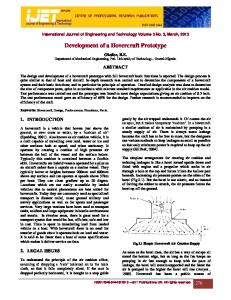
Abstract The main aim of this research work is to develop and design a proto type model for a pick and place robotic vehicle with a soft catching gripper that can be controlled by android OS for remote operation. At the transmitting end using android application device, commands are sent to the receiver to control the movement of the robotic vehicle. Meanwhile at the receiving end four motors are interfaced to the microcontroller where two for them are used for arm movement while the other two are for the body movement. The android application device transmitter will acts as a remote control while the receiver end Bluetooth device is fed to the microcontroller to drive DC motors via motor driver IC for necessary work. Remote operation is achieved by any smart phone with Android OS; upon a GUI (Graphical User Interface) based touch screen operation. Keywords: pick and place, bluetooth technology, robotic vehicle Copyright © 2015 Institute of Advanced Engineering and Science. All rights reserved.
1. Introduction Primary study is required to refer the information or technical knowledge that is critical to develop the designs in order to meet the expectations. Several literature reviews had been performed. R.Anusuya Devi presented one research paper aimed at the design and constructs a pick and place robotic vehicle which is powered by solar energy. The robotic vehicle designed can be operated without having any power supply; it can automatically generate the electricity which is completely utilized by the robot itself with the help of 8051 microcontroller, solar panels and Light Dependent resistors (LDR). The paper presents a robotic system that is capable of both picking up and releasing micro objects with high accuracy, reliability, and speed [1]. The system employs a novel micro electromechanical systems (MEMS) micro gripper with a controllable plunging structure to impact a micro object that gains sufficient momentum to overcome adhesion forces. Highspeed, automated micro robotic pick-and-place was realized by visually recognizing the micro gripper and microspheres, by visually detecting the contact of the micro gripper with the substrate, and by vision-based control. Fadnavis Shubham had presented a paper that proposes to a new and unique technique to regulate wireless car with the help of GUI through Visual Basic tool [2]. GUI is the main controlling system that generates four different coded signals which are generated with the help of visual basic. These signals were transmitted and receive by the FM receiver and process for dc motor rotation. In the paper of Automation of Mobile Pick and Place Robotic System for Small Food Industry, the purposed is to design a microcontroller based on reliable and high performance robotic system for manufacturing line [3]. A special gripper is designed to pick and place the objects with flexibility. The system consists of three basic subsystem which is 1) Moveable base, 2) Rotational manipulator which consists a stepper motor that move in step angle to 360 degree and 3) the Magnetic gripper unit based on electromagnetic effect which operate on 12V DC signal. In the article of the Wireless Remote Control Car System Based on ARM9, it had state that the wireless robot system is usually composed by a microcontroller system which usually constrained by hardware characteristics and difficult to satisfy many complex control while ensuring system real-time [4]. View of this, the article based ARM9-structured processor and embedded Linux system, optimized and improvement the versatility and real-time capacity of wireless remote control car. The robot system collected the data by sensors and transmits the Received November 2, 2014; Revised January 26 2015; Accepted February 15, 2014
TELKOMNIKA
ISSN: 2302-4046
111
data to the PC console by WIFI. PC sent the final commends to robot and the robot executes them [5].
2. Materials and Methods The materials required for the development of prototype, model in this research work has been discussed in detail. 2.1. DC Motors (Brushed RF-500TB-12560) A DC motor is an electric motor that runs on direct current (DC) electricity. In any electric motor, operation is based on simple electromagnetism. A current-carrying conductor generates a magnetic field; when this is then placed in an external magnetic field, it will experience a force proportional to the current in the conductor and to the strength of the external magnetic field. The internal configuration of a DC motor is designed to harness the magnetic interaction between a current-carrying conductor and an external magnetic field to generate rotational motion. 2.2. AT89S52 Microcontroller A microcontroller module built on a high performance CISC CPU AT89S52, 40-pin with 8K bytes of in-system programmable CMOS and high- density nonvolatile Flash memory technology. The microcontroller having 32 programmable I/O lines, three 16-bit timer/counters and up to 8 interrupt sources. 2.3. L293D Motor Driver ICs L293D is a dual H-bridge motor driver integrated circuit (IC). Motor drivers act as current amplifiers since they take a low-current control signal and provide a higher-current signal. This higher current signal is used to drive the motors. L293D contains two inbuilt Hbridge driver circuits. In its common mode of operation, two DC motors can be driven simultaneously, both in forward and reverse direction. Figure 1 shows the connection of L293D to two DC motor.
Figure 1. L293D connection
2.4. LM7805 Voltage Regulator The LM78XX/LM78XXA series of three-terminal positive regulators are available in the TO-220/D-PAK package and with several fixed output voltages, making them useful in a Wide range of applications. A voltage regulator 7805 is used to get the constant 5V DC supply. 2.5. MCT2E Octo – Couplers Opto-isolators are a 6 pin IC made up of 1 LED and a transistor but with no electrical connection between the two, just a beam of light. Figure 2 show the functional block diagram of MCT2E. If input of the diode is zero and other end of diode is ground then the output will be one. When logic zero is given as input it doesn’t conduct which gives logic zero as output. When logic 1 is given as input it makes transistor switched on and this makes the output is logic zero as collector of transistor is connected to ground. Development of Prototype Model for Wireless Based Controlled Pick and… (Mr. Low Kok Hau)
112
ISSN: 2302-4046
Figure 2. Block Diagram of MCT2E
2.6. Bluetooth Breakout Board (Receivers) A Bluetooth module transmits data via low-power radio waves. It communicates on a frequency of 2.45 gigahertz.The low power limits the range of a Bluetooth device to about 10 meters (32 feet). Bluetooth doesn't require line of sight between communicating devices and can connect up to eight devices simultaneously within the same radius. 2.7. Blue Control V2.0 (Application) A basic universal remote control for Bluetooth enabled devices such as Android based smart phone to a microcontroller.
3. Proposed Model The proposed model uses Bluetooth technology as a communication protocol to communicate with the AT89S52 microcontroller with duly pulled up resistors. The program is written so that every time button pressed from the smartphone interface (Blue Control V2.0), the corresponding ASCLL code for the label will be sent to the Bluetooth module allocated on the robotic vehicle. Thus the exact characters transmitted is received by the receiving Microcontroller at its input pins so that appropriate output is available at port 2 to drive motor driver IC L293D for movement of the robotic vehicle in forward backward and left right movement. To other motors are also used for an operation up & down and gripper operation open & closed through series resistor of 10 ohms/2 watt from the output of the second motor driver IC L293D. Thus while motor operates in normal condition the running current results 0 normal voltage drop across the 10R/2W ohm resistor as the motor can run in clockwise (or) anticlockwise. A bridge rectifier comprising of 4 numbers 1N4007 are used with potential divides arrangement at it dc output to drive LED type opto-isolator such as MCT2E. The potential divider is so adjusted that the voltage at the LED of adjusted that the voltage at the LED of the opto-isolator is in sufficient to drive the internal transistor into conduction.
Figure 3. Block diagram of entire system for the robotic vehicle. TELKOMNIKA Vol. 14, No. 1, April 2015 : 110 – 115
TELKOMNIKA
ISSN: 2302-4046
113
So that a P-N-P transistor BC557 is devoid of biasing current that holds the interrupt 0 pin at logic high being connected from its emitter. While for any reason motor is brought to locked rotor condition owing to overload or reaching the dead end develops a higher voltage at the 10 ohm resistor that in turn switched ON the opto-isolator LED that finally drives the PnP transistor to GND bringing the interrupt 0 to logic zero state. The program is so written that once interrupt zero occurs low, no such command would generate any input to the motor driver IC for any direction for that motor movement .Only the other direction rotation is possible from the command. This helps in soft catching arrangement of the arm gripper to avoid extra pressure applied to the objects to be picked and also its up and down movement similarly. Figure 3 shows the block diagram of entire system.
4. Result and Discussion The process flow of the entire system is shown in below Figure 4. When the users press the button on the Blue control application, the ASCII code will be transmitted to the microcontroller through the Bluetooth module located at the robotic vehicle. The microcontroller will generate the correct output to the motor driver for the DC motor movement. In this model, a interrupt function is use in order to stop the movement of the arm and gripper when for any reason the DC motor is brought to locked rotor condition owing to overload or reaching the dead end when the gripper picked an object.
Figure 4. Process Flow
Some diagram of the prototype was shown at below. Figure 5 shows the internal view of the prototype base and Figure 6 shows the way of the printed circuit board was place inside the robotic vehicle. Meanwhile Figure 7 show the diagram of the robotic arm, gearbox and the mechanical gripper. Finally Figure 8 show the side view of the entire pick and place robotic vehicle.
Development of Prototype Model for Wireless Based Controlled Pick and… (Mr. Low Kok Hau)
114
ISSN: 2302-4046
Figure 5. Vehicle Base (Internal View)
Figure 6. Circuit Board and Base Plate
Figure 7. Robotic Arm and Mechanical Gripper
Figure 8. Pick And Place Robotic Vehicle (Side View)
Step-by-step Instruction Manual to use the Prototype: 1) First of all search for Blue Control V2.0 (Figure 9) at Google Play and install the app. 2) After installing, go to the apps and ready for usage. 3) Turn on the Bluetooth and scan for the device called “Linvor” or “HC-05”and connected to the device by enter pin 1234. 4) Go to the Blue Control app and press the options button and click the connect option. Then it will give a list of devices available. See for “Linvor” or “HC-05” and again enter the pin 1234 and then clicks “OK”. 5) Wait for a while until it gives the confirmation “Connected to Linvor or HC-05” then the app now ready for communication with the Bluetooth module in the pick and place robotic vehicle. 6) Below are the operation procedure: 7) Click up button for Robot Forward 8) Click down button for Robot Backward 9) Click left button for Robot Left 10) Click right button for Robot Right 11) Click A button for Robot Gripper Open 12) Click B button for Robot Gripper Close 13) Click C button for Robot Arm Up 14) Click D button for Robot Arm Down 15) Click centre button for Stop operation
TELKOMNIKA Vol. 14, No. 1, April 2015 : 110 – 115
TELKOMNIKA
ISSN: 2302-4046
115
Figure 9. Bluetooth Remote Control Interface (Blue Control V2.0)
5. Conclusion The robotic vehicle is designed with a soft catching gripper that can be controlled by android OS based smartphone available in the market for remote operation. The android application device transmitter will acts as a remote control while the receiver end Bluetooth device is fed to the microcontroller to drive DC motors via motor driver IC for necessary work. Remote operation is achieved by any Smartphone with Android OS; upon a GUI (Graphical User Interface) based touch screen operation. Users friendly and inexpensive in price are some of the advantages of Bluetooth technology used in controlling the robotic vehicle. Therefore controlling the robotic vehicle by smart phone will come true. The prototype can be further enhanced by interfacing it with a wireless camera so that the person controlling it can view operation of the arm and gripper remotely and with the IR sensors to allow the robotic vehicle to avoid any obstacles while moving to the destination point.
References [1] P Sathya Priya, P Rathi, R Anusuya Devi. Smart Host Microcontroller based solar powered tool with robotic arm. International Journal of Mechanical Engineering and Robotics Research. 2013; 2(3): 1522. [2] Yong Zhang, Brandon K, Chen, Xinyu Liu, Yu Sun. Autonomous robotic pick-and-place of micro objects. IEEE transactions on Robotics. 2010; 26(1): 200-207. [3] Fadnavis Shubham. A design of GUI Based Wireless Robotic Car. Research Journal of Engineering Sciences. 2012; 1(2): 26-31. [4] Mir Sajjad Hussain Talpur, Murtaza Hussain Shaikh. Automation of Mobile Pick and Place Robotic System for Small Food Industry. IEEE Digital Library. 2012: 522-526. [5] Wang Shaokun, Xiao Xiao, Zhao Hongwei. The Wireless Remote Control Car System Based on ARM 9. International Conference on Instrumentation, Measurement, Computer Communication and Control. Beijing. 2011: 887-890.
Development of Prototype Model for Wireless Based Controlled Pick and… (Mr. Low Kok Hau)