Home
Search
Collections
Journals
About
Contact us
My IOPscience
Development of software for digital image processing for analysis of neuroangiogenesis
This article has been downloaded from IOPscience. Please scroll down to see the full text article. 2011 J. Phys.: Conf. Ser. 332 012031 (http://iopscience.iop.org/1742-6596/332/1/012031) View the table of contents for this issue, or go to the journal homepage for more
Download details: IP Address: 186.124.209.240 The article was downloaded on 28/12/2011 at 19:13
Please note that terms and conditions apply.
SABI 2011 Journal of Physics: Conference Series 332 (2011) 012031
IOP Publishing doi:10.1088/1742-6596/332/1/012031
Development of software for digital image processing for analysis of neuroangiogenesis M A Gonzalez1,2, V L Ballarin1, A R Celín 2,3, M Rapacioli2,3, J J López-Costa2,4 and V Flores2,3,4 1 Laboratorio de Procesos y Medición de Señales, Facultad de Ingeniería, UNMdP , ARGENTINA 2 CONICET: Comisión Nacional de Investigaciones Científicas y Tecnológicas. 3 Grupo Interdisciplinario de Biología teórica. Departamento de Ciencias Bioestructurales, Universidad Favaloro, ARGENTINA. 4 Instituto de Biología Celular y Neurociencias. “Prof. E. De Robertis”, U.B.A. ARGENTINA. E-mail:
[email protected] Abstract. The process of formation, growth and distribution of vessels within the developing central nervous system is difficult to analyze due to the complexity of the paths and branches within the system. The study of images of this area poses particular problems because the high levels of noise, blurring and poor contrast often prevent the objects of interest detected correctly. The design of algorithms for digital image processing suitable for this type of imagery remains a constant challenge. The aim of this work is to develop a computer tool to assist the specialist in processing these images. This paper proposes the use of morphological grayscale reconstruction and other morphological operators in order to segment the images properly. The results show that the algorithms allow a suitable segmentation of the objects of interest. Moreover, the interface developed for processing enables easy and simple analysis of them by the specialists.
1. Introduction Each organ has a typical spatial distribution of blood vessels depending on the requirements of nutrients and gases and structural and functional characteristics [1.2]. This spatial distribution is made during embryonic development. However, the needs of nutrients and oxygen to developing tissues are not dependent on the functions of terminally differentiated organ but of the requirements related to compliance own development cell behavior [3,4]. Nervous and circulatory systems develop early, and they share typical peripheral distribution. Vessels and peripheral nerves in the body usually travel together forming “neurovascular” bundle [5]. The CNS (Central Nervous System) also has a great influence on the organization of the perineural vascular plexus that provide irrigation [6], the number of vessels entering to it [7] and the distribution of the plexus that irrigate it [8]. There is a great difficulty in evaluating the wealth of intrinsic blood irrigation of the CNS, the mass of tissue that each entrant vessel supplies (unit neura-vessel: uN-V) because the vessels that enter it branch profusely and generate a network of varying complexity. This paper proposes a strategy that requires computer assistance to determine precisely the site of entry for each vessel to the CNS, log and quantification of their relative positions and demarcation of areas of influence (uN-V) of each the pial surface. [9,12]. The aim of this work is to develop a computer tool to assist the specialist in processing and analyzing these images. This paper proposes the use of morphological grayscale reconstruction and other morphological operators to segment images of entrant vessels correctly to the CNS [13-17].
Published under licence by IOP Publishing Ltd
1
SABI 2011 Journal of Physics: Conference Series 332 (2011) 012031
IOP Publishing doi:10.1088/1742-6596/332/1/012031
2. Materials and Methods We analyzed images obtained from the pial surface of the developing CNS (Tectum optical chick embryo 6 days) that were previously processed by the diaphorase technique [18] allowing selectively stain the endothelial cells that line the light developing blood vessels. This technique allows to observe: (a) the surface segments of the vessels that enter the CNS, (b) entry sites and (c) the pial surface areas surrounding each cell (Fig. 1). All algorithms were implemented using the libraries of Mathematical Morphology and Image Processing Matlab R14. Moreover, the software was developed using the library of Matlab Graphical Interface (GUI).Figure 1 allows us to observe one of these test images.
Figure 1. Pial surface image of the developing CNS stained with the diaphorase. Figure 1 shows small truncated cones that correspond to the segment superficial radial vessels entering the CNS. The thickest point of these "cones" corresponds to the site of entry of each vessel. As can be seen each entrant vessel is surrounded by a "sphere of influence" or uN-V. 2.1.Mathematical Morphology This paper proposes the application of morphological operators to process test images, images of the CNS entrant vessels. For several years the mathematical morphology, theory based on the algebra of sets, has been applied in biomedical images with very good results and minimal Computational cost making it a helpful tool [9-12]. Morphological operations can be defined through the algebra of sets [13-15]. There is a rigorous representation of the theorems where you can get a morphological expression in terms of more primitive operations. The choice of a morphological operators and a way of structuring element depends on the particular application [1617]. These techniques are widely used in digital image processing, for example in edge detection, filtering, enhancement and restoration, segmentation and noise suppression. Morphological filters are more suitable for shape analysis than conventional linear filters. Binary morphology is defined from two basic operations called erosion and dilation. These operations compare the subsets within the binary image with a pattern called a structuring element. The structuring element is moved through the entire image. The erosion of the set A by the structuring element B(x) ⊂ ℜn is defined as: = AΘ B
{ x , B ( X ) ⊂ A}
being B ( x) ={b + x, b ⊂ B }
(1)
As it is widely known, the result of the erosion is one if the structuring element is included in the subset and zero if it not included.
2
SABI 2011 Journal of Physics: Conference Series 332 (2011) 012031
IOP Publishing doi:10.1088/1742-6596/332/1/012031
The dilation of A by the structuring element B(x) ⊂ ℜn is defined as:
A = ⊕B
{x B(x) ∩ A ≠ ∅}
(2)
The result of the dilation is one if there is at least one pixel of intersection between the subset of the original image and the shifted structuring element and it is zero when the intersection is empty. Binary morphological reconstruction dilates small sets included in the original image called markers. Binary reconstruction can select the original image marked objects (called mask) and display them in a new binary image with its size and shape. Giving a set A called mask, a structuring element B and a set called mask M, binary reconstruction (Eq. 4) is defined by the conditional A ⊕ Bc (M ) dilation, (Eq. 3) as: A ⊕ Bc (M ) = (M ⊕ B ) ∩ A
ρ A (M ) = lim( A ⊕ Bc ( A ⊕ Bc ( A ⊕ Bc ...(M )))) n →∞ n times
(3) (4)
Conditional dilation is defined as the dilation of the subset of the image marker, M, as long as the result of this dilation is contained in the mask, A. When conditional dilation is applied successively, it meets idempotency property when no changes occur in the image. The reconstruction is ρ A (M ) met when the resulting image does not changed more. As mathematical morphology for binary images, morphological grayscale operations are defined by the erosion and dilation. Given an image f (x, y) within domain Df and a structuring element B (x, y) within a Df domain the erosion of f by B is defined as: f ΘB= (s, t) Min { f(s + x, t + y) − B(x, y) (s + x), (t + y) ∈ D f ;(x, y) ∈ DB}
(5)
For each pixel of the image, the erosion is defined as the minimum difference between the intensities of the shifted structuring element and the corresponding intensities of the original image Given an image f(x, y) within domain Df and a structuring element B(x, y) within a DB domain is defined by the dilation of f by B is defined as: (6) f ⊕ B= (s, t) Ma x{ f(s − x, t − y) + B(x, y) (s − x) ∈ D f ;(x, y) ∈ DB} For each pixel of the image, the dilation is defined as the maximum of the sum of the intensities of the subset of the original image and the intensities of the corresponding structuring element. Given a gray level image, S, called mask and another gray level image called marker, M. Conditional dilation is defined as the successive dilation by the structuring element B, as follows: d B= d B (M ) ∩ S ,S (M )
(7)
ρ S ( M ) = lim(d B , S (d B , S (d B , S (d B , S ( M ).....)))) n →∞
(8)
n veces
The morphological grayscale reconstruction can be defined the same way that the binary reconstruction based on conditional grayscale dilation. When the conditional dilation is applied successively, ideally it meets idempotency property (no change occurs in the image). The resulting image is called reconstruction.
3
SABI 2011 Journal of Physics: Conference Series 332 (2011) 012031
IOP Publishing doi:10.1088/1742-6596/332/1/012031
In Figure 2 we can see the result of the reconstruction of a row of an marker image g, using an image f as a mask. The g image is dilated until the intersection of the result with the mask f are not exceeded .
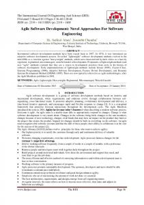
Figure 2. Morphological grayscale reconstruction. 2.3. Proposed Algorithm First, a morphological gray scale reconstruction from the edges of the image was applied. Then, the reconstructed image was subtracted from the original image. This operation was used to remove noise and background. Then the gradient was obtained by subtracting the reconstructed image form de original. This gradient was equalized to increase the contrast and, thus, highlight objects of interest. Finally, the threshold of the resulting image was obtained using the algorithm proposed by Otsu. This algorithm calculates the optimum threshold separating two classes (e.g. foreground and background) so that their intra-class variance is minimal [19]. Figure 3 shows a block diagram with the main procedures of the proposed algorithm. Figure 4 shows the segmentation obtained for one of these images.
CALCULATE THE EDGES OF THE ORIGINAL IMAGE
MORPHOLOGICAL GRAYSCALE RECONSTRUCTION USING THE EDGES OF THE ORIGINAL IMAGE AS MASK
SUBTRACTION OF THE RECONSTRUCTED IMAGE FROM THE ORIGINAL IMAGE
GRAYSCALE GRADIENT OF THE SUBTRACTED IMAGE EQUALIZATION OF THE GRADIENT
BINARIZATION OF THE GRADIENT
Figure 3. The block diagram illustrates the stages of the segmentation algorithm used.
4
SABI 2011 Journal of Physics: Conference Series 332 (2011) 012031
IOP Publishing doi:10.1088/1742-6596/332/1/012031
2.4. Graphical interface In order to assist the specialist in processing these images we developed a graphical interface that allows the automatic segmentation of images and also the improvement of them by adding missing items and removing irrelevant objects. This tool also allows determining the Watershed Transform of segmented elements. This operation is useful in analyzing the layout of objects of interest in the acquired sample. Figure 4 shows that interface.
Figure 4: Graphical interface
4. Results The preliminary results show that the developed algorithms allow a suitable segmentation of objects of interest. The developed algorithms were incorporated into a graphical interface that allows the specialist to automatically segment the images and improve the segmentation result of adding or removing objects from the image obtained. Figure 5 shows some of these results in conjunction with the developed interface. While the results are still preliminary and the tool evaluation itself is qualitative. All the algorithms that are part of the tool have been validated in previous articles. Despite this, it is expected to perform a full validation in the near future upon completion of the analysis for the normal variations in the Uvn that occur during experimental conditions in the regulatory processes interference that control the neuroangiogenesis.
5
SABI 2011 Journal of Physics: Conference Series 332 (2011) 012031
IOP Publishing doi:10.1088/1742-6596/332/1/012031
Figure 5: Some results obtained by applying the proposed algorithm
4. Conclusions Neuroangiogenesis concept refers to all processes to ensure integrated development of vessels and nerve tissue [20]. Such integration is regulated by endothelial cell interactions in development on the one hand, and neuroprogenitor stem cells, neurons or glial cells in development, on the other [21]. These interactions are mediated by signal molecules that spread from cell to cell and exert their effects in the corresponding soft cells [22]. These are networks of messages whose effects fluctuating subsume some randomness difficult to grasp and measure by conventional methods of analysis. This work shows that computer assistance can detect, record, quantify and highlight properties because of its variability are difficult to describe. The algorithms developed allow detecting and accurately recording the sites of the CNS entry of vessels. The developed software also allows delimiting their areas of influence (Uv-n) in the pial surface and based on this data to estimate the volume of neural tissue supplied by each vessel that enters the system. Using a graphical interface facilitates the analysis of the images analyzed, allowing the expert to improve the result of automatic segmentation. The interface provides a simple procedure that allows the specialist to process and quantify properties in a large number of images with low computational cost. The software developed will be useful for analyzing the normal variations that occur in the Uv-n during normal development as well as their changes under experimental conditions that interfere in the regulatory processes that control the neuroangiogenesis. Alterations in these regulatory processes are the cause of many abnormalities present at birth or appear throughout postnatal life. 5. References [1] Risau W. In: Development of the Vascular System of Organs and Tissues. Schaper W, Schaper J, editors. Kluwer Academic Publishers; Boston, pp. 17–28 (1993). [2] Risau W. Mechanisms of angiogenesis. Nature.386, pp.671–674 (1997).
6
SABI 2011 Journal of Physics: Conference Series 332 (2011) 012031
IOP Publishing doi:10.1088/1742-6596/332/1/012031
[3] Crossley DA 2nd, Burggren WW, Altimiras J. Cardiovascular regulation during hypoxia in embryos of the domestic chicken Gallus gallus. Am J Physiol Regul Integr Comp Physiol. 284(1), pp.219-226 (2003). [4] Lee YM, Jeong CH, Koo SY, Son MJ, Song HS, Bae SK, Raleigh JA, Chung HY, Yoo MA, Kim KW. Determination of hypoxic region by hypoxia marker in developing mouse embryos in vivo: a possible signal for vessel development. Dev Dyn. 220(2), pp.175-86 (2001). [5] Mukouyama, Y. S., Shin, D., Britsch, S., Taniguchi, M. and Anderson, D. J. Sensory nerves determine the pattern of arterial differentiation and blood vessel branching in the skin. Cell 109, pp.693-705 (2002). [6] Hogan KA, Ambler CA, Chapman DL, Bautch VL. The neural tube patterns vessels developmentally using the VEGF signaling pathway. Development.131(7), pp.1503-13 (2004). [7] Herken R, Gotz W, Wattjes KH. Initial development of capillaries in the neuroepithelium of the mouse. J Anat.164, pp.85–92 (1989). [8] Michael R. Mancuso, B.S., Frank Kuhnert, Ph.D., and Calvin J. Kuo. Developmental Angiogenesis of the Central Nervous System. Lymphat Res Biol. 6(3-4) pp: 173–180 (2008). [9] Castleman K. R., Digital Image Processing, Prentice Hall (1979). [10] Serra, J. Image Analysis and Mathematical Morphology, Academic Press, London (1982). [11] Glasbey, C. A. y Horgan G. W., Image analysis for the biological science, Statistics in Practice, Series Editor Vic Barnett., Jonh Wiley and Sons (1994). [12] González, R y Woods, R., Tratamiento Digital de imágenes, Addison Wesley (1996). [13] Facon, J., Morfología Matemática. Teoría y ejemplos, Curitiba Brasil, CITS (1996). [14] Serra, J., Image Analysis and Mathematical Morphology- Part II: Theoretical Advances,, Academic Press, London (1988). [15] Serra J. Image analysis and Mathematical Morphology, Academic Press (1992). [16] Ballarin, V. y Valentinuzzi, M.: “Segmentación en imágenes de Resonancia Magnética de Cerebro utilizando Morfología Matemática,” Actas del Congreso Argentino de Bioingeniería. Tafí del Valle. Septiembre 2001. (Publicadas en CD) (2001). [17] Heijmans, H., “'Theoretical aspects of gray-scale morphology,” IEEE Trans. Pattern Anal. Mach. Intell., 13, pp.568-582 (1991). [18] Scicolone G, Ortalli AL, Alvarez G, López-Costa JJ, Rapacioli M, Ferrán JL, Sanchez V, Flores V. Developmental pattern of NADPH-diaphorase positive neurons in chick optic tectum is sensitive to changes in visual stimulation. J Comp Neurol. 494(6), pp.1007-1030 (2006). [19] N. Otsu, “A threshold selection method from gray-level histograms”, IEEE Trans. on SMC, 9, pp. 62-66 (1979). [20] Louissaint A, Jr, Rao S, Leventhal C, Goldman SA. Coordinated interaction of neurogenesis and angiogenesis in the adult brain. Neuron. 34, pp.945–960 (2002). [21] Shen Q, et al. Endothelial cells stimulate self-renewal and expand neurogenesis of neural stem cells. Science.304, pp.1338–1340.(2004) [22] Ogunshola OO, et al. Neuronal VEGF expression correlates with angiogenesis in postnatal developing rat brain. Brain Res Dev Brain Res., 119, pp.139–153 (2000).
7