IEEE TRANSACTIONS ON NUCLEAR SCIENCE, VOL. 53, NO. 4, AUGUST 2006
2131
Development of the Optical Multiplexer Board Prototype for Data Acquisition in the TileCal System V. González, Member, IEEE, E. Sanchis, Member, IEEE, J. Soret, J. Torres, J. Castelo, V. Castillo, C. Cuenca, A. Ferrer, E. Fullana, E. Higón, J. Poveda, A. Ruiz, B. Salvachúa, C. Solans, J. A. Valls, A. Munar, C. Iglesias, and A. Valero
Abstract—This paper describes the development of the optical multiplexer board (OMB), also known as PreROD board, for the TileCal readout system in the ATLAS experiment. The aim of this board is to overcome the problems that may arise in the integrity of data due to radiation effects. The solution adopted has been to add redundancy to data transmission and so two optical fibers with the same data come out from the detector front end boards. The OMB has to decide in real time which fiber, eventually, carries data with no errors switching it to the output link connected to the read out driver (ROD) motherboard where data processing takes place. Besides, the board may be also used as a data injector for testing purposes of the ROD motherboard. The paper describes the design and tests of the first prototype, implemented as a 6U VME64x slave module, including both hardware aspects, focusing on signal integrity problems, and firmware aspects, dealing with the cyclic redundancy code algorithms used to check data consistency used to make the decision. Index Terms—Data acquisition, fault tolerance, field programmable gate arrays, integrated circuit radiation effects.
I. INTRODUCTION HE Large Hadron Collider (LHC) [1] is, presently, the main project of the European Laboratory for Particle Physics (CERN) in Geneva. The aim is to build a proton-proton collider able to explore the range of energy (in excess of 10 TeV) where new physics phenomena and particles are expected to be observed. In particular, the search for the Higgs boson is of great interest to explain the origin of mass. The collider is due to start working in 2007 and for the detection of the products of the collision two main particle detectors, ATLAS (A Toroidal LHC Apparatus) [2] and CMS (Compact Muon Solenid) [3] are under construction. Each detector is composed of several subdetectors specialised in the detection of different kind of particles. TileCal [4], the hadronic calorimeter of ATLAS detector, is one of these and will serve to measure the energy of hadrons. Good spatial resolution is of great importance and so TileCal is read through thousand of electronic channels which sum up a great amount of information to process in each collision.
T
The data acquisition of all this information poses new challenges in the development of new real time systems. In particular the traditional trigger level architecture has been updated with the most recent technological advances to fulfil all requirements of the system. The work presented is focused on the portion of the data acquisition system (DAQ) between the detector dependent and general ATLAS systems. There, the read out driver (ROD) system constitutes the last element prior to second level trigger guided data processing. For this ROD system, and because of radiation threat, the optical multiplexer board (OMB) exploits redundancy by selecting one of the two optical fibers coming out from the detector front end. The rest of the paper is organized as follows. Section II describes the ATLAS readout and trigger system while Section III focuses on the TileCal ROD system. Section IV presents the radiation problem that justifies the need of the Optical Multiplexer Board. In Section V, the description and design process of the OMB is presented. Section VI is devoted to OMB tests and results. Finally, Section VII summarizes the paper and presents the future work. II. ATLAS READOUT AND TRIGGER SYSTEM ATLAS trigger systems is built around the multilevel trigger concept which reduces the data acquired from the detector from 50 TB/s to 10–100 MB/s thanks to the low effective production cross section of the particles searched. This particularity allows the rejection of most of the data because they do not adjust to the characteristics sought. Fig. 1 shows the block diagram of the trigger system. Level 1 is detector dependent because it has to adjust to their particularities while level 2 and 3 are common to all subdetectors in ATLAS. In the interface between levels one and two, data gathering according to physical phenomena takes places and, depending on the detector, also data preprocessing can be performed. This functionality, among others is part of ROD systems [5]. III. TILECAL ROD SYSTEM
Manuscript received June 18, 2005; revised April 7, 2006. This work was supported by the Spanish Technology and Science Commission under project FPA2003-09220-C02-02. V. González, E. Sanchis, J. Soret, and J. Torres are with the Department of Electronic Engineering, University of Valencia, Burjassot, 46100 Valencia, Spain (e-mail:
[email protected]). J. Castelo, V. Castillo, C. Cuenca, A. Ferrer, E. Fullana, E. Higón, J. Poveda, A. Ruiz, B. Salvachúa, C. Solans, J. A. Valls, A. Munar, C. Iglesias, and A. Valero are with the Instituto de Física Corpuscular (IFIC), Edificio Institutos de Investigación, Paterna, 46071 Valencia, Spain Digital Object Identifier 10.1109/TNS.2006.877861
TileCal consists, electronically speaking, of roughly 10 000 channels which are read at the LHC bunch crossing rate (25 ns). At the ROD level, channels are gathered following the trigger towers. Also at this level, the ROD system preprocesses data values using calculating, in real time, the energy, timing and digital signal processing algorithms. These values for all the channels are sent to second level processors for further decision. Fig. 2 shows the schematic structure of the Tilecal ROD system.
0018-9499/$20.00 © 2006 IEEE
2132
IEEE TRANSACTIONS ON NUCLEAR SCIENCE, VOL. 53, NO. 4, AUGUST 2006
Fig. 1. The ATLAS three levels trigger system.
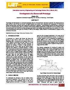
Fig. 3. Proton beam incidence position for radiation test of the OIB for large and small beam size.
IV. FRONT END RADIATION PROBLEMS
Fig. 2. TileCal ROD system.
For TileCal, the ROD system will be built with 32 custom VME boards which will treat around 2 Gbytes/s of data (300 channels per board). The basic schema to use is based on the ROD crate concept in which ROD modules are grouped into VME crates jointly with a trigger and busy module (TBM) [6] and possibly other custom cards when needed. This ROD crate interfaces with the TileCal run control and the ATLAS DAQ run control. The Tilecal ROD system is further subdivided into two subsystems: • the ROD motherboard [7]; • the optical multiplexer board (OMB) [8]. The ROD motherboard contains the full processing capability for the estimation of energy and time on data coming from the front end. The optical multiplexer board is included in the system to exploit data redundancy because of radiation problems that may arise in normal detector operation. This aspect is discussed in the next section.
The TileCal front end electronics is placed inside the detector. This makes the system sensitive to radiation produced by the particle collisions. In this sense, ATLAS specifications require the electronics to work properly for a period of 10 years. Different detectors have different needs in this matter, as presented in [9]. TileCal electronics will receive about 2 Gy/year (0.2 Krad/ year) of radiation for a total dose of 20 Gy in the experiment lifetime. The TileCal front end electronics that sends data to the ROD system is the optical interface board (OIB). This board has only two chips, a field programmable gate array (FPGA) and a digital-to-analog converter (DAC), sensitive to radiation and prone to fail [10]. The OIB was tested with proton beams in different areas and with different beam sizes. Fig. 3 shows the beam position for the tests using both large and small size beams. Thanks to these tests, three non-destructive kinds of errors were found in the OIB: • transient error in the data flow out to the ROD; • permanent errors in the data flow requiring FPGA reset; • latch-up error with an increment in current consumption of 60 mA. To reduce data loss due to radiation effects, the TileCal collaboration decided in February 2003 to include data redundancy in the output links of the OIB. This was accomplished using two optical fibers which transmit the same data. At ROD system
GONZÁLEZ et al.: DEVELOPMENT OF THE OPTICAL MULTIPLEXER BOARD PROTOTYPE FOR DATA ACQUISITION IN THE TILECAL SYSTEM
2133
level, data redundancy is used to discard the fiber with errors due to radiation. The checking is based on rightness of the cyclic redundancy codes (CRC) of the data packets on both fibers. This is also necessary as the ROD motherboard is expecting just one fiber per channel. For this purpose, a new module, called PreROD or optical multiplexer board, was conceived. V. OPTICAL MULTIPLEXER BOARD DESIGN As mentioned above, the primary target of the OMB is to improve the error tolerance analyzing the two fibers coming from the front end and providing the correct one to the ROD input. This analysis is based on the real time calculation of the CRC value of the data received on both input fibers. Once calculated, this value is compared to the one included within the data. If the values differ then the fiber is carrying defective data. Decision logic then selects which fiber will provide the data to the ROD motherboard, taking into account the results of the CRC checking. The other OMB functionality is data injection to ROD motherboard. In this mode, data can be loaded using VME bus and injected following an internal or external trigger signal. Internal triggering allows for the selection of the rate. The project of the OMB implementation started in October 2003 and the first OMB prototype is now finished.
Fig. 4. Optical multiplexer board block diagram.
TABLE I OMB MAIN COMPONENTS
A. Hardware Description The optical multiplexer board prototype has been designed as a 6U VME64x slave module architecture. It includes four optical inputs connectors (two input channels) and two optical outputs connectors integrated in the PCB. The input channels are capable to read up to 4 16 bits at 40 MHz and allow for testing different input technologies. The output also runs at 40 MHz with a data width of 16 bits. There are also four input G-Link chips (Agilent HDMP-1034) [11] on the board, two output G-Link chips (Agilent HDMP1032) [11], two FPGAs for CRC calculations (CRC FPGAs) and one FPGA for VME interface (VME FPGA). These last are implemented in ALTERA devices. Furthermore, for the data injector mode, the OMB has two additional copper input cables for trigger and busy signals coming from the ROD motherboard. These external signals are included in this prototype to send correctly internal data in order to test the ROD functionality. The block diagram of the board is shown in Fig. 4. A short description of the main functions of the G-link and FPGA chips in the OMB board is given in Table I. Following is a detailed description of the board is presented. 1) Input/Output Hardware: Four optical fibers coming from the front end boards (FEB) are the input to the OMB, and two optical fibers to the ROD are the output from the OMB using Infineon optical transceivers [12]. The G-link chips are used in the input and output stages, respectively, of the OMB board. These chips are used to build a high-speed data link for point-to-point communication. Input data comes into the four HDMP-1034 chips (one per input fiber) where they are deserialized and output as a 40 MHz 16 bit word data flow to the CRC FPGAs (one per input channel, i.e., two input fibers). The output data of each CRC FPGAs is a
16 bit word stream at 40 MHz to the HDMP-1032 chips where they are serialized and sent to the ROD motherboard. The HDMP-1032/1034 chipsets handle all the issues of link startup, maintenance, and simple error detection. 2) FPGA Description: Two CYCLONE EP1C12 FPGAs [13] are used in the OMB board for CRC checking and link control. They were chosen mainly because of their low cost. The incoming data from each pair of different G-link receiver chips are routed to one of these FPGA. Data are then analyzed and the decision is made on which data link is the correct one. Each CRC FPGA routes the correct data to its G-link transmitter chip. The other FPGA chip present in the OMB is the one controlling the access to the board through VME bus. The OMB module is considered as a VME slave module and all actions and commands are controlled by the crate CPU following the VME64 standard. The VME interface of the OMB is implemented in an ACEX EP1K100 [14]. VME map includes registers holding the number of CRC errors detected in the optical fibers, control registers to select CRC checking or injection mode and an event memory to load the data to inject if we use this mode. The addressing mode is A32D32 and the memory space also includes a CR/CSR space to conform to CERN specifications in this aspect.
2134
IEEE TRANSACTIONS ON NUCLEAR SCIENCE, VOL. 53, NO. 4, AUGUST 2006
Fig. 5. Differential lines topology from optical fiber connector to HDMP.
The VME FPGA exchanges data between the VME CPU and the two CRC FPGAs. 3) Data Distribution in OMB: There are two different functioning modes in OMB: CRC process mode and ROD Injector Data mode. In CRC mode, data coming from the FrontEnd using two fibers are received, deserialized and input to the CRC FPGA. This FPGA calculates the CRC values of the data block and compares the result to the CRC values contained in the same data block. This analysis is done in parallel for the two input fibers. After the last 16 bit word arrival, the system knows which fiber has no error and switches the output accordingly. Output data go to the serializer chip and, from there, to the optical transceiver to be sent to ROD motherboard. This process takes place at the same time for the two input links. If the OMB is working in Injection Mode then only the output fibers (and the corresponding serializers) are used. In this mode the data to send are stored in an event memory using VME bus transactions. The user can choose how to trigger these data: either externally (using NIM level signals) or internally thanks to a trigger generator programmed inside the VME FGPA. Once triggered, data are sent either to one or both of the CRC FGPA which sends them to ROD motherboard. The data injection can be stopped externally, if programmed in this way, by means of a busy signal. B. PCB Design On of the main aspects we cared about in the PCB design of the OMB was signal integrity. Clock frequency (40 MHz) and several 32-bit buses to be routed were the main concern in what respects to crosstalk. We carried signal integrity studies both in pre-layout and post-layout stages using Cadence SpecctraQuest software [15]. Pre-layout analysis let us to establish the routing rules and the chose of termination resistors, if needed. Post-layout analysis verified the design taking into account the PCB layer stackup.
Fig. 6. Received pulse at the HDMP input for different terminations.
As an example, the differential lines connecting the Infineon fiberoptic transceivers and the HDMP chips at 640 Mbps were studied in a pre-layout phase. In this case we established the equal routing length and let the software simulate the behaviour with different termination resistors. Fig. 5 shows the topology for this case. The results of the simulation for different resistor values are shown in Fig. 6. From them, a 180 ohm value was chosen as optimum termination. Another important issue in high speed digital design is clock distribution. In our case we had the option to mount just one clock for all the HDMPs as we used one clock for each FPGA. This option is very sensitive to trace distance and would imply strict routing rules which may lead (as we were very space limited) to an impossible routing solution. Besides, taking into account that input and output optical links need not to be synchronized, we preferred to use one clock device for each HDMP. Pre-layout simulations helped in this decision as the option with
GONZÁLEZ et al.: DEVELOPMENT OF THE OPTICAL MULTIPLEXER BOARD PROTOTYPE FOR DATA ACQUISITION IN THE TILECAL SYSTEM
2135
Fig. 7. Clock line reflection simulations for one clock.
Fig. 9. The optical multiplexer board prototype.
Fig. 8. Clock line reflection simulations for multiple clocks.
only one clock chip performed worse than the one with multiple clocks. Figs. 7 and 8 show the simulations for one clock and multiple clocks. As it can be seen, a multiple clock solution gives a better signal quality and so it was the solution adopted. The OMB was built using a 12 layer PCB. The layer stackup was designed to minimize crosstalk between layers by routing the adjacent ones orthogonally. Each two internal layers are between power or ground planes for this same reason. Optical transceivers and serializers/deserializers chip signal are preferably routed on the top layer for faster signal transmission. Buses are routed in parallel with equal trace length for minimization of skew. Fig. 9 shows a photograph of the OMB finally implemented. C. Firmware Description All the FPGA firmware in the OMB was developed with Altera Quartus II software [16]. The detailed description of this firmware follows. 1) CRC FPGA: The block diagram of this FPGA is shown in Fig. 10. There are two reception blocks (each one for each input fiber) and one transmission block. These blocks are connected to the CRC calculation, decision and data multiplexing logic where all these tasks are executed. The FPGA connects to the VME FPGA and to the CRC FPGA of the other input channel for control and in prevision of data sharing.
Fig. 10. Block diagram of the CRC FPGA firmware.
Another firmware block takes care of link control and we included the possibility of observing internal signal states through an external connector attached to each CRC FPGA. 2) VME FPGA: This FPGA implements an A32D32 single word VME slave module. It contains all the configuration and control registers of the OMB. In particular the working mode (CRC or injection) is directly configured here. Thanks to the connection to both CRC FPGA, the VME FPGA controls the operation of the whole OMB. Error counters are provided to make statistics on link failures and are accessible through VME. Fig. 11 shows the VME memory map of the OMB. There are registers holding the three different kinds of CRC values checked (odd words, even words and block) for each one of the four input fibers. For injection mode and internal trigger, frequency divider words are provided to adjust the trigger frequency. The base clock is 40 MHz. Also for this mode we can set a trigger loop; in this case we need to program the loop limit accordingly. Finally, the map includes the event memory for injection. Even this memory appears in the VME FPGA, physically, due to the actual design, the memory is held in the CRC FPGAs.
2136
IEEE TRANSACTIONS ON NUCLEAR SCIENCE, VOL. 53, NO. 4, AUGUST 2006
Fig. 13. OMB test setup at CERN laboratories.
VI. OPTICAL MULTIPLEXER BOARD TESTS
Fig. 11. OMB VME memory map.
Fig. 12. Status and control register map.
Fig. 12 shows the status and control register description where we can see the working mode, VME trigger mode configuration bits, CRC error counters resets and the event memory control.
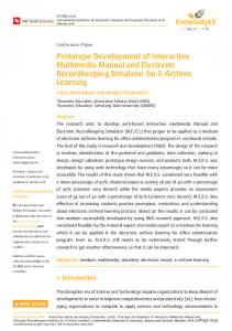
In July–August 2004, the first tests were carried out on the OMB prototype at CERN. These tests were intended to provide an overall look and debug its functionalities. Basic electrical tests were carried out at Valencia labs while the first input/output data flow tests were performed at CERN (Fig. 13). For this purpose, we used a custom data injector module to simulate data coming from the detector and a ROD motherboard as data receiver for the output fibers of the OMB. To test the data injector mode, the OMB directly output data to the ROD motherboard. We used a data acquisition software developed for the ROD motherboard control to check for data corruption or transmission errors. Final OMB tests were performed at Valencia labs during ROD module production. The test setup is shown in Fig. 14. It consisted of a ROD controller, implemented using a VP-110 single board computer, a trigger timing and control VME interface board (TTCvi) [17] for trigger and timing signalling, an OMB working as injector, an OMB working as CRC checker, a ROD motherboard for data analysis, and a PC equipped with a data acquisition board and corresponding software (XFILAR [18]). Data were generated at the OMB working as injector and sent to one or four ROD motherboards, depending on the test conducted, using an optical buffer depending on the test. Inside RODs data were checked and the results saved in the PC which also controlled the whole system. The system was run for more than 2000 hours injecting more than 3600 million of events at different frequencies of 200 Hz and 1 KHz with no errors. VII. SUMMARY AND FUTURE WORK This paper has described the design and tests of the first prototype of the optical multiplexer board or PreROD board. This board exploits data redundancy of front end links in the TileCal experiment. This redundancy is due to radiation problems that may occur in the electronics. The results of the tests, electrical and functional, have been successful.
GONZÁLEZ et al.: DEVELOPMENT OF THE OPTICAL MULTIPLEXER BOARD PROTOTYPE FOR DATA ACQUISITION IN THE TILECAL SYSTEM
2137
Fig. 14. ROD testbench at Valencia labs for data flow tests.
The design of the OMB is now undergoing a redesigning phase which includes the adoption of the final 9U board size, eight input channels (16 input fibers) and eight output channels, as well as trigger, timing and control (TTC) [19] signal decoding and VME full control (see Fig. 15). We expect to have a preproduction board series by third quarter 2006. Overall, a TileCal OMB has proven all its functionalities and we foresee the fulfilment of all requirements of the TileCal schedule. REFERENCES
Fig. 15. OMB final design block diagram.
[1] The Large Hadron Collider Accelerator Project, CERN AC/93-03(LHC), The LHC Study Group, 1993. [2] ATLAS Technical Proposal, CERN/LHCC/94-43, ATLAS Collaboration, 1994. [3] CMS Technical Proposal, CERN/LHCC/94-38, CMS Collaboration, 1994. [4] TileCal Technical Design Report, CERN/LHCC 96-42, TileCal Collaboration, 1996. [5] Trigger and DAQ Interfaces with FE Systems: Requirement Document, Version 2.0, DAQ-NO-103, ATLAS Trigger and DAQ steering group, 1998 [Online]. Available: http://atlas.web.cern.ch/Atlas/GROUPS/ FRONTEND/FEreq980310.pdf [6] P. Gallno, “The ATLAS ROD busy module,” in ATLAS ROD Workshop, Geneva, Switzerland, 1998 [Online]. Available: http://mclaren.home. cern.ch/mclaren/atlas/conferences/ROD/per.pdf [7] J. Castelo, “TileCal ROD hardware and software requirements,” ATL-COM-TILECAL-2005-002, 2005 [Online]. Available: http://doc.cern.ch//archive/electronic/cern/others/atlnot/Note/tilecal/ tilecal-2005-003.pdf [8] J. Torres, “Optical multiplexer board for TileCal data redundancy,” presented at the 9th Workshop on Electronics for LHC Experiments, Boston, MA, 2004. [9] Radiation test, TileCal Chicago Group, CERN, ATLAS Collaboration, 1999 [Online]. Available: http://hep.uchicago.edu/atlas/electr/ Rad_testing/Radiation_ Testing.html
2138
[10] K. Anderson, “SEE Test of the TileCal Optical Interface Board,” Enrico Fermi Inst., Univ. Chicago, 2001 [Online]. Available: http://hep. uchicago.edu/atlas/electr/interface_board/Writeup_of_SEE_Test.pdf [11] “HDMP-1032A/1034A Datasheet, Transmitter/Receiver Chip Set,” Agilent, 2001 [Online]. Available: http://cp.literature.agilent.com/ litweb/pdf/5988-3852EN.pdf [12] “V23818-K305-L18 Datasheet, Gigabit Ethernet Transceiver,” Infineon Tecnologies AG, 2001 [Online]. Available: http://www. datasheetarchive.com/datasheet/pdf/68/687493.html [13] “Cyclone Datasheet,” Altera Corp., 2003 [Online]. Available: http:// www.altera.com/literature/litcyc.jsp [14] “ACEX Datasheet,” Altera Corp., 2003 [Online]. Available: http:// www.altera.com/literature/litacx.jsp
IEEE TRANSACTIONS ON NUCLEAR SCIENCE, VOL. 53, NO. 4, AUGUST 2006
[15] “Allegro PCB SI, Allegro Design Entry CIS,” Cadence Design Systems, 2003 [Online]. Available: http://www.cadence.com/products/si_pk_bd/pcb_si/index.aspx [16] “Quartus II Software,” Altera Corp, 2005 [Online]. Available: http:// www.altera.com/literature/hb/qts/quartusii_handbook.pdf [17] Ph. Farthouat and P. Gallno, “TTC-VMEbus interface TTCvi - MkII, Rev 1.6,” CERN, RD12 Project, 2000 [Online]. Available: http://ttc. web.cern.ch/TTC/TTCviSpec.pdf [18] X. Poveda, “Standalone software for TileCal ROD characterization and system test,” ATL-COM-TILECAL-2004-012, 2004. [19] B. Taylor, “TTC distribution for LHC detectors,” IEEE Trans. Nucl. Sci., vol. 45, no. 4, pp. 821–828, Aug. 1998.