Development of Tools and Techniques for Monitoring Underwater Artifacts Iulian Lazar, Alin Ghilezan, Mihaela Hnatiuc
Electronic and Telecommunication Department,Constanta Maritime University, Romania
ABSTRACT The different assessments provide information on the best methods to approach an artifact. The presence and extent of potential threats to archaeology must also be determined. In this paper we present an underwater robot, built in the laboratory, able to identify the artifact and to get it to the surface. It is an underwater remotely operated vehicle (ROV) which can be controlled remotely from the shore, a boat or a control station and communication is possible through an Ethernet cable with a maximum length of 100 m. The robot is equipped with an IP camera which sends real time images that can be accessed anywhere from within the network. The camera also has a microSD card to store the video. The methods developed for data communication between the robot and the user is present. A communication protocol between the client and server is developed to control the ROV. underwater system, communication protocol, Ethernet, artifacts identification.
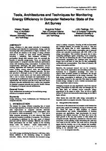
1. INTRODUCTION The development of advanced technologies and tools for identifying, diagnosing and excavating underwater artefacts are studied by many laboratory researchers [1, 2]. The difficulties are to identify the artifact using low costs and not to endanger the lives of divers. The ROV will be used to go down into the sea in search for lost historical artefacts. Research in the field of submarine automated systems were conducted and are conducted just to replace divers and provide information as identical as possible to theirs from the submarine environment. These automated systems should convey by wire as precisely as possible the information required underwater [3,4]. All their construction as well as the transmission means differ based on the properties presented by the water [10, 11]. Being equipped with sensors and a camera, they can convey information as precise as possible on the marine environment as well as on the water using adaptive performant algorithms. An optimization of the data transfer is being attempted by testing the various types of cables and communication protocols [5,6,7, 8]. The ROV (Remotely Operated Vehicle) system presented in this article is an underwater remotely operated vehicle. ROV a tethered mobile underwater device [9,12]. It is different from the remotely controlled vechicles that operate on the land and sea. The ROV does not have persons on board, is manoeuvrable and easy to operate by the crew on board a ship. This is connected to a host ship by cables transmitting information from the depth. The aim of building this system is to identify the artifacts and monitor the ecosystem in deep water and recover them by means of a brat robot. Monitoring the system sent on a mission into ater (ROV) is achieved by means of a workstation at the surface. The station at the surface receives the information required and the possible warnings from the ROV. The main information sent from the workstation are: coordinates, movement direction, acceleration, the type of the mission (Fig.1). 104 Bd. Mircea cel Batran, Constanta
[email protected]
Advanced Topics in Optoelectronics, Microelectronics, and Nanotechnologies VIII, edited by Marian Vladescu, Razvan Tamas, Ionica Cristea, Proc. of SPIE Vol. 10010, 100100V · © 2016 SPIE · CCC code: 0277-786X/16/$18 · doi: 10.1117/12.2243037 Proc. of SPIE Vol. 10010 100100V-1
Steering control System
/
Mission control System
Throttle control System
Ground Control Station
Warning System
Board/Ground communication
Fig.1 The main modules of the ROV monitored by means of the station at the surface
2. SYSTEM DESCRIPTION The underwater system is a small-scale one, being in the testing stage. The novelty introduced by this system is the transmission of data achieved between two Arduino Mega microcontroller plates connected by means of a K5 cable that will be introduced into the water with a depth of maximum 25m. The ROV system that provides the underwater monitoring is equipped with: Ardunino Mega, GPS, IMU sensor (inertial measurement unit) with accelerometer, giroscop and magnetometer, IP camera AirDome 30 fps, robot arm and 8 GB microSD card and four Brushless Navy brushless engines with low speed (approximately 750rpm / V) and maximum consumption 10 A (Fig.2). The workstation at the surface that is another Arduino Mega plate is connected to the ROV, a PS3 joystick and a computer. By means of the GPS systems from the ROV, the location where going into depth is identified, the coordinates trasmitted to the workstation being considered the 0 point where the movement into the water begins. The movement of the ROV is achieved by means of the engines, the direction and the acceleration being transmitted by the joystick through the workstation. The coordinates in real time are registered on the microSD card in a file with the .log, extension, which, after the ROV finishes its mission, are downloaded into the computer. They are import in google earth in order to mark the route covered, the route being recreated. The pictures taken by the IP camera are registered on the microSD card and transmitted in real time to the workstation and displayed on the computer by means of a brat robot. By using AutoCAD and a 3d printer, we managed to make custom parts to fit our mechanical needs for mounting and securing electronic components like the ESCs and Microcontrollers.
1
Fig.2 The block diagram of the autonomous underwater seeker system
Proc. of SPIE Vol. 10010 100100V-2
The system presented in Fig.3 covers three important points: Program/Application - Vehicle Control; Management System; Safety Level for the critical situations; Arduino hardware and software Problem - Transform conventional underwater into ROV; Reduce the human resource; Increase the quality and reliability of the underwater system Results - Saved money and life; Easing maintenance tasks; Give many pieces of information about the water world
Legend:
v1. Power supply 2. Arduino UNO with USI3 Shield
3. POE Poner Injector 4. WiFi Router
E
5. IP Camera 6. Ethernet SWITCH
7. rduinoN£GA
Fig,3. The presentation of the real components integrated into the system and the sealed box The acceleration is set from the joystick, with potentiometers that can achieve 2 rotations and 3 translations that modify the direction of the engines. Between the Arduino plates, two types of communication protocols: TCP/IP and RS485 have been tested precisely to notice which one is more stable in case the ROV will be corroborated at a low depth (over 25m).
3. COMUNICATION AND TESTS RESULTS The underwater data transmission and security are an important problem of communication. The communication of data is established between the joystick and Arduino Mega, considered as the workstation (Master) and, between this one and the Arduino Mega plate on the ROV, considered as Slave. The types of data are integer types, establishing the movement direction and acceleration, the coordinates where the ROV is in real time. In our system, the first tests for data communication between two Arduino Mega are established by Ethernet using the TCT/IP protocol. In order to establish the first TCP/IP communication, programming is achieved in Arduino Software 1.6.9 using dedicated functions from its libraries. The direction on the 3 XYZ axes is controlled by means of the joystick, the information being transmitted from the Master on the SPI port to the Slave. For the command and information reading from the joystick, the PS3USB.h library is used. The PS3.getAnalogHat( ) function reads the position of each handle of the joystick as an analogical value (Fig.4.), delimited by || and consequently, it is saved in the XL, YL, XR, YR variables in the int format.
Proc. of SPIE Vol. 10010 100100V-3
XL = PH3.getAoalogHat(LeftHatX(; YL = PH3.getAaalogHat(LeftHatY(; XR = PH3.getAoalog9at(RightHatX(; YR = PH3.getAaalogHat(RightHatY);
?I (622'dgcyug?oàggc(r6icRgcX) >?3J
I
I
623'dgtSNg?udHgt(P6gHgtX)