Available online at www.sciencedirect.com
Physics Procedia 36 (2012) 914 – 920
Superconductivity Centennial Conference
Development, testing and installation of a Superconducting Fault Current Limiter for medium voltage distribution networks Luciano Martinia, Marco Bocchia, Massimo Ascadea, Angelo Valzasinaa, Valerio Rossia, Giuliano Angelia, Cesare Ravettab b
a RSE S.p.A., via Rubattino 54, 20134 Milano, Italy A2A Reti Elettriche S.p.A., via Ponte Nuovo 100, 20128 Milano, Italy
E-mail:
[email protected]
Abstract Since 2009 Ricerca sul Sistema Energetico (RSE S.p.A.) has been involved in the design of resistive-type Superconducting Fault Current Limiter (SFCL) for MV applications to be installed in the A2A Reti Elettriche S.p.A distribution grid in the Milano area. The project started with simulations, design and testing activities for a singlephase device; in this paper we report on the successive step, which is concerned with developing, testing and installation at the hosting utility of the final three-phase SFCL prototype. The result of this research activity is a resistive-type 9 kV/3.4 MVA SFCL device, based on first generation (1G) BSCCO tapes, developed by RSE in the framework of a R&D national project. Owing to the positive test results of partial discharge, dielectric and shortcircuit results the three-phase SFCL device is being to be installed in the A2A distribution grid in the Milano area and it is going to be soon energized starting a one-year long field-testing activity.
©2012 2011Published Published by byElsevier Elsevier B.V. Ltd. Selection and/or peer-review under responsibility of Horst Rogalla and © the Guest Editors. Peter Kes. under CC BY-NC-ND license. Open access Keywords: Short-circuit current; Superconducting Fault Current Limiter; critical current; AC losses; short-circuit test; dielectric test; shunt reactors; partial discharge test; short-time power-frequency test; cryostat; bushing; current leads; flange; liquid nitrogen
1. Introduction The Superconducting Fault Current Limiter (SFCL) is an innovative device that, when properly designed and placed in appropriate positions in an electrical grid, is able to limit the short-circuit current ISC to values compatible with safety and reliability of the installed network components [1]. Among all different types of SFCL nowadays under study, resistive-type SFCL are expected to be one of the first technically and economically viable applications of High Temperature Superconductors (HTS) [2-3]. By
1875-3892 © 2012 Published by Elsevier B.V. Selection and/or peer-review under responsibility of the Guest Editors. Open access under CC BY-NC-ND license. doi:10.1016/j.phpro.2012.06.229
Luciano Martini et al. / Physics Procedia 36 (2012) 914 – 920
exploiting their intrinsic properties, HTS have characteristics that make them particularly suitable for this type of device: their electrical resistivity, in fact, undergoes a sudden rump-up when they are carrying currents whose instant value exceeds a threshold called "critical current" (Ic), conventionally defined by using the electric field criterion of 1μV/cm. Silver-alloy sheathed BSCCO-2223 tapes, first generation (1G) wires, are historically the most applicable solution for usage at the temperature of 77 K [4]; nevertheless, many applications of YBCO coated conductors second generation (2G) wires, are nowadays in course of study [5-6]. From the utilities point of view, the SFCL is highly attractive, as it provides not only a solution to deal with the growing level and incidence of fault currents, but also facilitates innovative planning of electricity grids[7]. A2A Reti Elettriche S.p.A., one of the largest Italian utilities, has already experienced high fault current level at different positions within its MV network and identified a few very suitable locations in its 23 kV and 9 kV grids where a SFCL device could be efficiently installed. In this work we report on the development, testing and installation of a resistive-type SFCL device for MV applications, performed in the framework of an Italian RTD project aimed at installing a resistivetype SFCL device in the A2A distribution grid in the Milano area. As a first step, a single-phase SFCL device for MV applications was developed and successfully short-circuit tested [1]. In this paper, the development, testing and realization activities devoted to installing the final three-phase resistive-type SFCL device for feeder [2] MV applications at the hosting utility are described. 2. SFCL Design Principles According to the considered grid location (Table 1), a SFCL device enabling a limitation factor LF = 1.7÷2, being this value the ratio between the prospective ISC in the absence of SFCL and the limited current ILim in the presence of the SFCL device, is highly desirable. In the past, RSE developed MVAclass single and three-phase SFCL prototypes with solenoid winding design, constituted by HTS layers anti-inductively wound on fiberglass cylinders [8, 9]. This configuration is able to dramatically lower (almost annihilate) the magnetic self-field [10]. The SFCL device is made up by means of a HTS tape total length equal to 1880 m. The HTS material used is a multifilamentary stainless steel reinforced silver–alloy sheathed BSCCO-2223 tape insulated by a helicoidally wound Kapton layer with a 50% overlapping and thickness of 12.5 μm. The 1G HTS tape overall cross-sectional dimensions are 4.65 mm x 0.37 mm (including insulation). The self-field critical current at 77 K is about 180 A. Each phase is constituted by three series-connected HTS windings coaxially arranged, moreover each phase is shunted by an air-reactor of 0.4 ȍ with power factor cosij equal to about 0.1. Each winding is realized by two HTS layers anti-inductively wound on fiberglass cylinders and between the two layers a supplementary insulation Kapton layer (125 μm thick) is added. Table 1. Network requirements Parameter
A2A requirements
Rated voltage
Vnom = 9 kV
Rated current
Inom = 220 A
Prospective short-circuit current
ISC = 12.3 kArms
Maximum prospective short-circuit current
ISCP = 30 kAp
Prospective short-circuit power factor
cosijSC = 0.1
Ungrounded short-circuit duration
tfault = 400 ms
Limitation factor = ISC / ILim
LF = 1.7 - 2
915
916
Luciano Martini et al. / Physics Procedia 36 (2012) 914 – 920
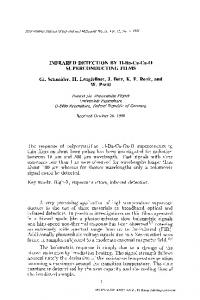
The three phases are inserted in a liquid nitrogen bath within a cryostat 1800 mm high and characterized by an internal diameter of 600 mm. A closed-circuit Stirling LN liquefier, with cooling power of 1000 W at 77 K (700 W at 65 K) is used for the SFCL refrigeration. 3. SFCL main characterizations 3.1. Critical current (Ic) measurements Ic measurements have been performed at 65 K and 77 K for each winding of the three-phase device. Since each phase is made up of three coaxially arranged windings, nine HTS windings have been tested. To reduce the possible stress applied to the HTS windings, Ic measurements were performed to electrical fields up to about 0.3 μV/cm and the critical current at 1 μV/cm has been then estimated by means of proper exponential fitting functions. The Ic measurement carried out on phase R1, R2, R3 and the resulting curve for the whole phase R are reported in Fig. 1. 3.2. AC losses measurements The HTS windings have undergone the experimental procedure for the evaluation of AC losses, which consists in injecting 50 Hz modulated-amplitude sinusoidal-AC currents in the HTS windings immersed in a liquid nitrogen bath at 77 K. During the measurement, voltage drop across winding terminals and injected current have been acquired with a sampling frequency of 100 kHz for a time-interval of ten periods (200 ms). Experimental data have been acquired, processed and then compared with those calculated by the Norris equation [11]. Fig. 2 shows the AC losses for phase R as function of the injected current amplitude. In particular, the three coaxial windings R1, R2, R3 are considered separately and the experimental measurements are compared to the analytical results calculated by the Norris equation; moreover, the total AC loss for the whole phase R elaborated starting from the experimental measurements of each coil is also reported; clearly the Norris equation is not able to properly approximate AC losses for the phase under test. 1,2
500 Phase T1 - Measurements Phase T2 - Measurements
400
Phase T3 - Measurements
0,8
AC losses (mW/m)
Electrical field ( μ V/cm )
1,0
TLN2 = 65 K
TLN2 = 77 K
0,6
0,4
Phase T as a whole
TLN2 = 65 K
300
200
TLN2 = 77 K 100
0,2
0,0 140
0 160
180
200
220
240
260
280
300
320
340
360
380
Injected DC current (A)
Fig. 1. Critical current measurement for the whole phase R at the temperature of 77 K
400
40
60
80
100
120
140
160
180
200
220
240
260
280
300
320
340
360
Injected AC current peak value (A)
Fig. 2. AC losses at 77 K versus injected 50 Hz sinusoidal current peak amplitude
4. SFCL qualification and acceptance tests SFCL technology has to overcome a relevant obstacle in order to become marketable: nowadays no standards are available because the application of SFCL in power systems is not common yet. Qualification tests concerned with insulation may be considered as the most conventional activity. This allows to consider the existing standards and to adjust them in compliance with the unique features of the device. One of the aims is to look for possible drawbacks in manufacture and this goal may be reached by means of a proper Partial Discharge test (PD); moreover, insulation is to be tested in order to validate the
Luciano Martini et al. / Physics Procedia 36 (2012) 914 – 920
dielectric withstand capability of the device and this goal may be reached by means of the short-duration power-frequency withstand voltage test and of the Basic Impulse insulation Level test (BIL) [12-14]. SFCL acceptance tests are the most innovative activity because they are aimed at proving the device capability of limiting short-circuit currents in agreement to the networks requirements provided by the hosting utility. On one hand, alike the qualification tests the lack of a proper standardization forces to adjust the existing technical norms [15] to the SFCL device; on the contrary, tailored current testing procedures are to be set in order to validate its limiting capability. In the following, the results of both dielectric and short-circuit testing activities are presented: the first has recently been performed, the latter was performed during the first quarter of 2011. Both tests have been successfully completed. 4.1. Dielectric tests It is mandatory to test the SFCL device in the same conditions as for its nominal operation in field. For example, the cooling system has to be working during the test and cryostat must be filled in with liquid Nitrogen (LN2). The test full voltages (V0) for the short-duration power-frequency withstand voltage test and for the BIL were equal to 28 kVrms and 60 kVp respectively [13]. 4.1.1. Short-duration power-frequency withstand voltage test The test procedures followed at RSE laboratories adhere to international standard recommendations, that for what concerns the present application may be briefly summarized as follows [14]: • The test is to be performed for each SFCL phase individually, i.e. three-times in total. When one single phase is supplied, all the other terminals (the other two phases), cryostats and external vessel must be earthed. The phase supplied is characterized by one terminal connected to the voltage source, while the other terminal is kept floating (or short-circuited with the terminal supplied) • The test commences at a voltage not greater than one-third (i.e.,