460. Height. 76 mm. Tertiary winding material. BISCCO. Winding type. Circle .... Trans. Power App. Systems, vol. PAS-95, no. 1, pp. 394â400, Jan. 1976. 176.
International Conference on Computer Information Systems and Industrial Applications (CISIA 2015)
Development of a High Temperature Superconducting Controllable Reactor Based on Finite Element Method M. Song
Z.T. Yu, B. Sun, B.Ch. Chen, J.X. Yuan
Yunnan Electric Power Test & Research Group Co., Ltd. Electric Power Research Institute Kunming City, Yunnan Province, China
School of electrical engineering, Wuhan University Wuhan, Hubei Province, China
Abstract-A new 40kVA, 400V high-temperature superconducting (HTS) controllable reactor of transformer type has been designed, built and tested. The reactor has totally 3 windings and utilize Bi2223 HTS materials to wound the inside two windings which are responsible for the adjust of the reactor’s reactance. A finite element model was developed and simulation was conducted to predict its performance, such as capacity, harmonic and response. Then experiments were carried out and results are compared.
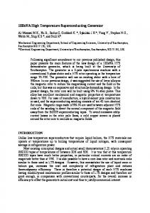
inside two HTS windings (secondary and tertiary winding) control the capacity of the reactor. The primary winding being given a sinusoidal voltage, the flux traversing the HTS loop will stay invariant when HTS coil is closed according to the conservation of flux in a superconducting loop. The variant flux can only pass through the gap between the closed HTS coil and ordinary coil. Reactance changes as a result of the change of flux.
Keywords- high temperature superconducting (HTS); finite element model; controllable reactor
I.
Secondary winding
Tertiary winding
Iron core
INTRODUCTION
Since control of reactive power is important and significant for a transmission network, many kinds of devices are developed to cater for such demand [1]. However, most of them are characterized by one or more demerits as high harmonics component, slow response, complex control and high cost etc.[1]-[4].While Thyristor Controlled Reactor(TCR) injects lots of harmonics into the system[2], Magnetically Controlled Reactor(MCR) responses slowly and reactors of transformer type have relatively large losses[3][4].
Primary winding
FIGURE I. STRUCTURE OF HTS REACTOR.
R1
K3
R` 3
X` 3
K2
R` 2
X2`
X1
U1 Rc
Meanwhile, as superconducting technology develops, superconductor power equipment is expected to make a significant impact [5]. Till now, some superconducting reactors have been devised, but almost all of them are confined to fault current limiters [6][8].
Xc
FIGURE II. EQUIVALENT CIRCUIT.
Since its structure is similar to that of a three-winding transformer, its equivalent circuit can be depicted in Fig 3. By short circuiting secondary or tertiary winding, i.e. closing switch K2 or K3, the equivalent inductance (of the primary) will vary. Its working modes are listed in Table. I.
Combining the technology of controllable reactor and superconductivity, this paper proposes a novel High Temperature Superconducting (HTS) controllable reactor of transformer type, which is mainly applied for reactive power compensation.
TABLE I. Working mode S1 S2 S3 S4
This paper applies a finite element analysis method to the computation of the reactance of the HTS reactor. A prototype of HTS reactor is built and experiments are carried out. Some discrepancies between computation and experimental results and possible causes are analyzed.
WORKING MODE OF HTS REACTOR. Switch status K2、K3 open K2 opened,K3 closed K2 closed,K3 opened K2、K3 closed
Impedance X1+Z0 X1+X3 X1+X2 X1+X2//X3
III. COMPUTER MODELING AND SIMULATION II.
BASIC PRINCIPLE
Literature [9][10] proposed a finite element method, as shown in Fig.4, to calculate the reactance components of the Steinmetz exact transformer equivalent circuit. However, it is only possible for a two-winding transformer. In order to
Structure of the HTS reactor can be simplified as in fig.1. It has a three-limb core. The primary winding, i.e. the outside winding which is made up of aluminum wire, is designed to provide reactive power for system when at work, while the
© 2015. The authors - Published by Atlantis Press
173
Lij N i N j Pij
acquire the reactance components in Fig.2, we need to simulate for 3 times.
(7)
Lik N i N k Pik
(8)
L jk N j N k Pjk
FIGURE III. FINITE ELEMENT ANALYSIS OF A FULL CORE TRANSFORMER.
That is the three windings are named i, j and k respectively, three permeance matrixes for an n layer HTS reactor of transformer type are defined as
PB
L Pb
PC
Where
L
Sb( j)Sb( j)
L Sc
nPac
L
Pc( k )Pc(i )
k 1 i 1 ik
Sc( k )Sc( k )
k 1
PCjk PCkj
(13)
nPc nPc
Pc( k )Pc( k )
nSc
L
Sb( j)Sb( k )
j 1 k 1 k j
k 1
(3)
(12)
nPb nPb
L
(2)
L
Pb( j)Pb( k )
j 1 k 1 k j
j 1
L Pc
(11)
nPb nPb
Pb( j)Pb( j)
nSb
L
Sa(i )Sa( j)
i 1 j 1 i j
nPb
L
(10)
L
Sa(i )Sa(i )
j 1
L Sb
Pa(i )Pa( j)
nPa nPa
(1)
Where PBik PBki PC1n PCnn
L
nPa
i 1 j 1 i j
i 1
PB1n PBnn
PC11 P Cn1
nPa
L
Pa(i )Pa(i )
nSa
L Sa
Where PAij PAji PB11 P Bn1
nPa
L
L Pa
i 1
PA11 PA1n P PAnn An1
PA
(9) Each time, two windings are selected and we call one of them primary and the other secondary. The primary and secondary windings are formed via series connections of one or more layer sections. Assume W is the set of winding layer sections (numbered from the inside) while P and S be subsets of containing and elements, respectively. Let P(i) and S(j) denote the ith and jth element of P and S. The self-inductances of primary and secondary winding are then given by [12]
(14)
nPc nPc
L
Sc( k )Sc(i )
k 1 i 1 ik
(15)
The mutual inductance is given by,
Each P is obtained from finite-element software by performing n simulations. In each simulation, a single winding layer, assigned with a unity number of turns, is excited with unit current, and a row of is calculated by
nPa nSa
M PaSa
L
Pa(i )Sa( j)
i 1 j 1
(16)
nPb nSb
Pij
λi ij
M PbSb
Pjk
λi ik
Pb( j)Sb( k )
j 1 k 1
(4)
(17)
nPc nSc
Where λ i is the flux linkage of layer due to an excitation i current j in winding i. And,
Pik
L
M PcSc
L
Pc( k )Sc(i )
k 1 i 1
(18) Then, the inductances are transformed into the reactance components of the Steinmetz exact transformer equivalent circuit using
(5)
Xa 1 jw(L Pa xM PaSa )
λj
x 2 Xa 2 jwx 2(LSa
ik
(6) The winding section inductance matrix L can then be obtained from P. The elements of are calculated as [11]
Then,
174
1 M PaSa ) x
(19) (20)
Xa Xa 1 x 2 Xa 2 jw(L Pa x 2 LSa 2xM PaSa ) (21)
By the same way, it can be calculated that
Xb Xb1 y2 Xb 2 jw(L Pb y2 LSb 2yMPbSb ) Xc Xc1 z 2Xc 2 jw(L Pc z 2 LSc 2zM PcSc )
(22)
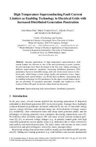
FIGURE IV. PROTOTYPE OF HTS REACTOR.
IV. MODELING RESULTS The modeling of Section II was used to design a threewinding, single-phase, 380-V, 30-kVA HTS Reactor. Table II gives the physical dimensions and materials used in the design of the reactor. The parameters of Table II and Table III were entered into a computer program written using the modeling methods of Section II. The program was able to determine the equivalent circuit parameters for the HTS reactor design.
FIGURE V. WINDINGS OF THE HTS REACTOR. TABLE IV.
REACTANCE (Ω) OF HTS REACTOR. Voltage
TABLE II.
MAIN PARAMETERS OF HTS REACTOR.
parameter Rated voltage Rated current Capacity Phase Operating frequency Iron core type Magnetic flux density Height TABLE III.
Unit V A kVA Hz
Designed value aluminum 430/580 170 410 BI-2223 Circle 286/306 10 460 76 BISCCO Circle 240/260 12 352 208
200V
300V
350V
380V
400V
S1
454
800
600
290
211
181
—
S2
6.25
6.17
6.42
6.24
6.09
6.23
6.23
S3
5.46
5.29
5.61
5.34
5.22
5.28
5.37
S4
5.03
4.87
5.17
4.92
4.8
4.87
4.94
TABLE V.
E core 1.6 550
COMPARATION OF CALCULATION SIMULATION AND EXPERIMENT (UNIT Ω).
T mm
Xa Xb Xc
SPECIFICS OF WINDINGS.
parameter Primary winding material Diameter (inner/outer) Number of turns Height Secondary winding material Winding type Diameter(inner/outer) Number of layer Number of turns Height Tertiary winding material Winding type Diameter(inner/outer) Number of layer Number of turns Height
V.
value 380 80 30 Single 50
Unit
Averag e
100V
simulation 6.83 5.84 5.75
experiment 6.23 5.37 4.94
From Table.V, the results of simple calculation may have a quite large error as the size of the three windings are a little irregular.
Mm mm
The results of simulation and experiment are generally in consistent with each other. The discrepancy between simulation and experiment are due to that the actual size of the primary winding is different from that in the model.
mm
mm
VI. CONCLUSION The inductance changing principle of high-temperature superconducting (HTS) reactor is illustrated, a finite element model is built. And electromagnetic simulation and computation is conducted and a 380V experimental HTS controllable reactor was designed, based on which an experiment is conducted. Small discrepancies appeared between the simulation and experiment and the cause was analyzed.
mm
mm
EXPERIMENTS AND DISCUSSION
Finally we built a prototype of a HTS reactor. However, in the process of manufacturing, the primary winding is built in a square shape. Experiments are carried out under 100V, 200V, 300V, 350V and 380V. Reactance under every experiment is calculated and listed in Table. IV.
REFERENCES [1]
[2]
[3]
175
Mingxing, T., L. Qingfu and L. Qunfeng, A controllable reactor of transformer type. Power Delivery, IEEE Transactions on, 2004. 19(4): p. 1718-1726. Mutluer, B., Cadirci, I,, Ermis. M., et al., "A unified relocatable SVC for opencast lignite mining in Turkey," IEEE Transactions an Industry Applications, vol.40,no.2,p p. 650 - 663,2004. A. M. Bryantsev, "Magnetic thyristor reactive power regulator," Elektrotekhnika, vol. 55, pp. 111–115, Oct. 1984. in Russian.
G. N. Aleksandrov, B. I. Al’bertinskii, and I. A. Shkuropat, “Operating principles of controllable shunt reactor of transformer type,” Elektrotekhnika, vol. 66, pp. 42–47, Nov. 1995. in Russian [5] Wass, T., S. Hornfeldt and S. Valdemarsson, Magnetic circuit for a controllable reactor. Magnetics, IEEE Transactions on, 2006. 42(9): p. 2196-2200. [6] Yamaguchi, H. and T. Kataoka, Current Limiting Characteristics of Transformer Type Superconducting Fault Current Limiter With Shunt Impedance and Inductive Load. Applied Superconductivity, IEEE Transactions on, 2008. 18(2): p. 668-671. [7] Hong, Z., et al., The Structure, Performance and Recovery Time of a 10 kV Resistive Type Superconducting Fault Current Limiter. Applied Superconductivity, IEEE Transactions on, 2013. 23(3): p. 56013045601304. [8] Naeckel, O. and M. Noe, Design and Test of an Air Coil Superconducting Fault Current Limiter Demonstrator. Applied Superconductivity, IEEE Transactions on, 2014. 24(3): p. 1-5. [9] S. C. Bell and P. S. Bodger, “Inductive reactance component model for high-voltage partial-core resonant transformers,” Inst. Eng. Technol.Elect. Power Appl., vol. 2, no. 5, pp. 288–297, 2008 [10] Lapthorn, A.C., et al., HTS Transformer: Construction Details, Test Results, and Noted Failure Mechanisms. Power Delivery, IEEE Transactions on, 2011. 26(1): p. 394-399. [11] C.-M. Ong, Dynamic Simulations of Electric Machinery: Using MATLAB/SIMULINK. Upper Saddle River, NJ: Prentice-Hall, 1997. [12] K.Wirgau, “Inductance calculation of an air-core disk winding,” IEEE Trans. Power App. Systems, vol. PAS-95, no. 1, pp. 394–400, Jan. 1976.
[4]
176