2016 The Authors. Published by Elsevier Ltd. Peer-review under responsibility of SINTEF Energi AS. Keywords: Offshore structures; wind turbines; dynamics; full ...
Available online at www.sciencedirect.com
ScienceDirect Energy Procedia 94 (2016) 425 – 433
13th Deep Sea Offshore Wind R&D Conference, EERA DeepWind'2016, 20-22 January 2016, Trondheim, Norway
Development, Verification and Validation of 3DFloat; Aero-Servo-Hydro-Elastic Computations of Offshore Structures. Tor Anders Nygaarda* Jacobus De Vaala Fabio Pierellaa Luca Oggianoa Roy Stenbroa a
Institute for Energy Technology (IFE), PO Box 40, 2027 Kjeller, Norway
Abstract The aero-servo-hydro-elastic Finite-Element-Method code 3DFloat is tailored for nonlinear, coupled time-domain simulations of offshore structures in general and offshore wind turbines in particular. This article describes the theory behind the structural model, aerodynamic and hydrodynamic load modules, control system and coupling with an optimizer. The verification and validation history includes the IEA OC3/OC4/OC5 projects, two wave tank tests and participation in commercial projects. Current development examples include implementation of advanced hydrodynamics in the DIMSELO project, implementation of soil/structure interaction super-elements in the REDWIN project, and optimization of large rotors with sweep in an industry project. © 2016 The Authors. Published by Elsevier Ltd. This is an open access article under the CC BY-NC-ND license © 2016 The Authors. Published by Elsevier Ltd. (http://creativecommons.org/licenses/by-nc-nd/4.0/). Peer-review under responsibility of SINTEF Energi AS. Peer-review under responsibility of SINTEF Energi AS Keywords: Offshore structures; wind turbines; dynamics; full coupling
1876-6102 © 2016 The Authors. Published by Elsevier Ltd. This is an open access article under the CC BY-NC-ND license (http://creativecommons.org/licenses/by-nc-nd/4.0/). Peer-review under responsibility of SINTEF Energi AS doi:10.1016/j.egypro.2016.09.210
426
Tor Anders Nygaard et al. / Energy Procedia 94 (2016) 425 – 433
1. Introduction Computation of loads, motions and stresses for flexible offshore structures subject to concurrent wind- and wave loads poses several challenges. The problem requires knowledge of diverse topics such as aerodynamics, hydrodynamics, structural dynamics, electrical machinery and control theory. Nonlinear interactions between e.g. large platform motions, rotor loads and controller actions often leads to populating large case matrices (realizations of wind, waves and fault conditions) with time-domain computations. For offshore wind turbines, in particular for floating systems, cost reductions are required to make an impact in the energy system. This means the computations have to be accurate, to avoid overly conservative designs, and efficient to aid a streamlined engineering process, where the detailed time-domain simulations can be an integrated part of the design and optimization loops. The primary purpose of our in-house code 3DFloat is to serve as a platform for innovation, research and education on offshore structures and aero-servo-hydro-elastic computational methods. However, as the model matures through verification and validation efforts, participation in commercial engineering projects with demanding users is increasing, providing valuable feedback to the code developers. In 2006, when this work started, very few codes for offshore wind turbines, with access to the source code and sufficient generality to aid development of new innovative conceptual designs existed. Anticipating large flexible (multi-) rotors and complex substructures, we were interested in a general framework allowing more detailed loadand structural models to be added as the industry progressed. Due to the severe cost constraints for offshore wind turbines, some optimized floaters require modelling as flexible bodies. This is needed to provide accurate solutions of eigen frequencies for the complete structure, and to provide detailed load transfer and stress distributions. It was therefore decided to make a model from scratch with a general core, with load and element type modules tailored for nonlinear time-domain simulation of flexible offshore structures by the Finite-Element-Method (FEM). This fits well with other core activities at IFE, where technical software for the industry based on FEM has been a significant activity for more than 40 years. 2. Model description 2.1. Structural model The core of the model is a nonlinear corotational FEM framework, where computational nodes are interconnected with elements. The elements implemented so far are based on Euler-Bernoulli beams with 12 Degrees-of-Freedom (DOF). The elements store structural, aerodynamic and hydrodynamic properties with respect to the two section principal axes and the axial direction. Geometric nonlinearities are accounted for by a co-rotated FEM approach, where the reference configuration is a recently deformed state. The element equations are stated in a coordinate system attached to the midpoint of the element in the reference state, and then transformed to a common component coordinate system. This allows for the utilization of small-strain elements for large global deflections, as long as the element resolution is sufficient. Additional elements include cable elements for chains, wires and fiber ropes; generator elements; blade pitch actuators; linear, quadratic and hysteresis dampers; soil/structure interaction superelements and peak-load shaving fairlead actuators for connection of the mooring lines. The time domain computations are carried out using either the implicit Generalized-Į� PHWKRG�� WKH� LPSOLFLW� Newmark scheme, or an explicit central difference scheme [1]. For the implicit schemes, modified Newton subiterations are used for the convergence of the solution in each time-step, governed by a residual criterion. Eigen-frequency analysis with 3DFloat is handled with all displacement dependent external loads linearized and added to the stiffness matrix at the relevant DOF. This includes the effect of buoyancy, mooring lines and restoring moment due to metacentric height. The results include eigen frequencies, corresponding mode shapes and visualizations of the modal motions. 3DFloat can export geometric information, motions and stresses for visualization and animation with Tecplot, ParaView, and a suite of Python scripts included in the 3DFloat package. Multiple instances of wind turbine rotors, actuators and controllers can be combined with structural elements to build new innovative conceptual designs, such as combined wind/wave power plants. The FEM formulation in
Tor Anders Nygaard et al. / Energy Procedia 94 (2016) 425 – 433
3DFloat allows each element to act as an independent body, providing flexibility in connecting and disconnecting substructures during the simulations.
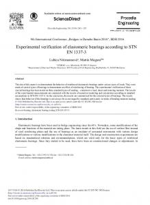
Figure 1: Animation of Motions and Stresses with 3DFloat
2.2. Loads
Loads from gravity, buoyancy, waves, current and wind are applied as distributed external loads on the structure. Forces are evaluated at Gauss points in the elements, and a Galerkin approach is used to evaluate consistent nodal loads. Wind is handled as a nonlinear drag term on the structure above the wave surface, except on airfoil elements, where lift- and drag lookup tables are used. The loads for the wet elements are computed from relevant combinations of wave kinematics and force models. Regular wave kinematics is either linear finite water-depth Airy-theory or stream functions up to order 12 [2]. First order irregular waves, long- or short crested are obtained by superposition of linear Airy wave components. The wave component tables can be computed from JONSWAP or Pierson- Moskowitz spectrum definitions with either constant frequency or constant energy increments. The wave component tables can also be generated directly from time-series of wave height, from e.g. wave tank experiments, or imported from an external source. Second-order, short or long-crested wave kinematics [3] has recently been implemented and verified. This is computationally demanding, and more work is needed before this is a practical option. Two options are available for evaluation of wave kinematics. In the ‘mean’ approach, the mean position of the geometry is used when computing wave forces. In the ‘updated’ approach, the updated configuration of both the structure and sea surface is taken into account when applying wave loads to the wet elements. For the Airy waves, several approaches are implemented to provide wave kinematics to the wave surface. In the Wheeler stretching approach, the wave kinematics calculated at the Still Water line (SWL) are applied to the wave surface, stretching the distribution between the surface and the seafloor. This creates variations in pressure extending further down than in the basic Airy formulation, influencing the heave excitation. In the extrapolated Airy theory, wave kinematics above the SWL is assumed to be the same as at the SWL, and elsewhere (for the wet elements) as in the basic Airy theory. This modifies the kinematics only within the wave crests. The pressure in the stream function formulation is calculated by the Bernoulli equation applied in a reference frame moving with the wave celerity. In this frame, the pressure and velocity fields are steady, and the total pressure height is uniform. The wave kinematics can optionally be updated and interpolated with a kinematic time step that is larger than the structure solver time step. This can give significant savings on computational speed, without much loss of accuracy.
427
428
Tor Anders Nygaard et al. / Energy Procedia 94 (2016) 425 – 433
Wave and current loads for slender beams are computed on the wet part of the structure using the relative form of Morison's equation [4]. Large bodies, such as the pontoons on a Submerged Floating Tunnel (SFT) and columns of a semisubmersible floater can be modeled with Linear Potential Theory (LPT) for moderate wave heights. For a given body shape, WAMIT [5], WADAM [6] or NEMOH [7] is used to compute the linear excitation force transfer function coefficients as a function of wave direction and period, and the frequency dependent added-mass and damping coefficient matrices. The results can be imported to 3DFloat and associated with bodies attached to nodes on the structure. In the time domain, the excitation forces follow directly from the transfer functions and wave components. The effects of frequency-dependent added mass and damping are computed via retardation functions and convolution integrals. The induced velocity by wind turbine rotors is computed with Blade Element/ Momentum theory (BEM), with enhancements for dynamic inflow and yaw errors, as described in [8]. The turbulence is modeled with import of turbulence files on the “HAWC” or TURBSIM formats, generated with e.g. the IEC Turbulence simulator or TURBSIM. 2.3. Control system The generic control system in 3DFloat is for a variable speed rotor, with fixed blade pitch angle below rated wind speed. Above rated wind speed, PI control of pitch angle is used to control rotational speed and thereby power [9]. Alternatively, similar controllers developed in the IEA OC3 project for the NREL 5 MW reference rotor are implemented. One of these controllers has been tuned to maintain stability for the OC3-HYWIND floating wind turbine [10]. 3DFloat has a Dynamic Link Library (DLL) interface to proprietary controllers supplied by companies with competition sensitive software, e.g. the Statoil controller for spar-buoy floating wind turbines. 2.4. Optimization module The ALSIM package at IFE [11] contains the optimizer INVALS. For the use with 3DFloat, it was enhanced with the new optimization algorithms “Efficient Global Optimization (EGO)”, “Genetic Algorithm (GA)”, “Bound Optimization BY Quadratic Approximation (BOBYQA)” and “DIviding RECTangles (DIRECT)”. General and flexible capabilities were included to allow the module to communicate with other simulation models through textfiles or scripts, without the need for linking of models. The design variables with limits are specified in the INVALS input, along with tags for identification of the design variables or derived quantities in the simulation model input templates. INVALS generates the 3DFloat input file from the template. The template is identical to the 3DFloat input file, except some header information, and formulas identifying how the selected input values are evaluated from the design variables. With the generated input, INVALS runs a script for submitting 3DFloat simulations, and subsequently a cost function executable that parses through the output files of 3DFloat. The cost function is evaluated and exported to a text file that is subsequently read by the optimizer. The constraints are implemented as penalty functions in the cost model. INVALS can work on parallel systems, e.g. by sending different instances of design configuration simulations to different processors. A brief evaluation of the new algorithms in INVALS was performed on a benchmark problem from the casting industry. This confirmed the known characteristics of each of the methods. In the optimization problems applied to 3DFloat and offshore wind turbines, the BOBYQA method [12] seems to work well [13]. 2.5. Computational throughput A detailed description of a floating wind turbine, submerged floating tunnel, or suspension bridge in one flexible body FEM formulation typically results in several thousand DOFs. Time domain computations of several thousand load cases (LC) with a fully nonlinear FEM formulation is a demanding task, which requires some care when setting up the computational environment in a design/optimization project. We have obtained the best throughput by compiling the code to run each LC on one single processor. As other comparable nonlinear FEM codes, this results in computational speeds several times slower than real-time, but all cases are computed simultaneously on a cluster or in cloud-computing. The benefit of bringing detailed time-domain computations into the design loop (by reducing
Tor Anders Nygaard et al. / Energy Procedia 94 (2016) 425 – 433
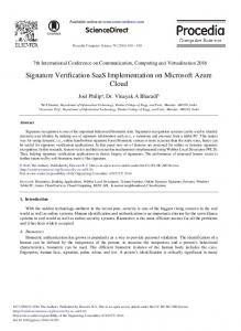
conservatism and associated material use) by automated LC-management, post-processing and reporting has been successfully demonstrated in a design study of a submerged floating tunnel for Bjørnafjorden by Dr.techn. Olav Olsen AS [14]. 3. Verification and validation 3DFloat was one of the software tools used to model the OC3-HYWIND floating wind-turbine in the IEA OC3 project [10], the bottom-fixed space-frame (“Jacket”) in the IEA OC4 project [15] and the semisubmersible platform in the IEA OC4 project [16]. It has been validated against wave tank experiments for 3 different Tension-LegBuoys [17] and a semisubmersible floater [18], several floater shapes in the IEA OC5 project [19] and forced motion of an isolated mooring line. 3DFloat has been used in conceptual design studies of Submerged Floating Tunnels (SFT) for Bjørnafjorden, with third party verification against SIMO/RIFLEX [14]. 3DFloat has been applied to a number of public and proprietary wind turbine rotors. The 3DFloat input for two public definitions are included in the package; the NREL 5MW reference rotor [20], and the DTU 10MW reference rotor [21]. Input for all substructures computed with 3DFloat in the IEA OC3/OC4 and OC5 projects are included. 4. Current developments 4.1. Advanced Hydrodynamics In the DIMSELO project (DIMensioning SEa Loads) we are developing and implementing advanced hydrodynamic models into 3DFloat and also addressing large rotors for offshore wind turbines. The project partners are IFE, DTU, NTNU Statoil and Statkraft. We have implemented Linear Potential Theory (LPT), 2nd order wave kinematics, enhancements of the Morisons equation such as the MacCamy-Fuchs force model for large monopile structures, and the Rainey non-linear force model for slender bodies in steep waves. Figure 2 compares the inline force for a bottom-fixed cylinder with diameter 6m at a water depth of 35m, subject to regular waves with wave height 16.6m and period 11.4s. The 3DFloat Morison and Rainey computations use stream function of order 12 for the kinematics. The Rainey and IFE in-house CFD results agree very well. The standard Morison model underpredicts the peak force by 15% compared to the Rainey and CFD results.
Figure 2: Comparison of Inline Force for a Bottom-Fixed Cylinder
429
430
Tor Anders Nygaard et al. / Energy Procedia 94 (2016) 425 – 433
Figure 3 shows surge and heave motions for an 80 x 30 x 8m pontoon used in a conceptual design study of a Submerged Floating Tunnel for Bjørnafjorden. The single pontoon is held in place with soft springs. The sea state corresponds to an effective wave height of 0.5m, and a peak period of 14s in the JONSWAP spectrum. As a first check of the LPT implementation, corresponding results from SIMO [22] are shown in the same figure.
Figure 3: Pontoon Heave and Surge Motions. Comparison between SIMO and 3DFloat results
4.2. Soil/structure interaction REDucing cost in offshore WINd by integrated structural and geotechnical design (REDWIN) is a R&D project supported by The Norwegian Research Council ENERGIX program. The project partners are NGI, IFE, NTNU, Dr.techn. Olav Olsen AS, Statoil and Statkraft. The primary objective of REDWIN is to contribute to reduction of costs in design of offshore wind turbines (OWT) by developing soil-foundation models that will account for key geotechnical issues such as stiffness, damping, drainage, degradation and long term behavior, and integrate them in the OWT structural models for more optimal analysis and design. As a first step, a macro-model consisting of translational and rotational springs with yield limits has been implemented in 3DFloat. Figure 4 shows the mudline overturning moment during an extreme operating gust starting at time 150s, combined with regular waves with wave height 3m and period 10s, for the 5MW OC3 Monopile wind Turbine [10]. The soil structure interaction is modelled with 8 springs, tuned to high-fidelity FEM computations for the pile and soil. The yield limits for this test were reduced by a factor two for the purpose of testing the numerical scheme. In the time histories, we can see how the peaks are flat when the springs reach the yield limits. This corresponds to moving clockwise around in the corresponding hysteresis curves. In the lower right graph, spring 5 does not reach its yield limit, and responds like a linear spring. Spring 6 cycles up and down the upper left slope of the hystereis curve before the gust, yields during the gust, and unloads down the slope on the righthand side of the curve. Spring 8 follows a similar pattern, and reaches also the yield limit at the bottom of the figure, goes though one intermediate reload cycle, before moving up and down along the slope in the left part of the figure during the waves after the gust. This first test confirms that the time stepping scheme of 3DFloat handles the nonlinearities in this soil/structure interaction model well.
Tor Anders Nygaard et al. / Energy Procedia 94 (2016) 425 – 433
Figure 4: Mudline Total and Selected Spring Moments vs. Time and Deflection Angle during Extreme Operating Gust
4.3. Advanced rotor aeroelasticity Offshore wind turbines favor large rotors due to high initial costs for substructure and grid connection. For long, slender and flexible rotor blades, taking into account offsets between the elastic axis and the shear- , aerodynamicand mass centers becomes more important. This also opens opportunities to control loads with measures such as bend/twist coupling and blade sweep. IFE is evaluating and optimizing rotors with sweep in a current industry project funded by Statoil. Figure 5 compares the aerodynamic rotor thrust during a gust for rotors with different versions of sweep. The wind speed up to time 0 is 12 m/s, steps up to 17 m/s, and back to 12 m/s after 5 s. The time is normalized with the nominal period for a rotor revolution. The thrust is normalized with the nominal thrust before the gust starting at time 0. Due to the finite pitch rate, the thrust overshoots almost 60% for the baseline rotor, before the blades pitch nose down to reduce the loads. On a rotor with the blades swept backwards on the outer part of the blades, an increase in thrust on the blades produces a torsional moment, corresponding elastic twist, and thereby reduction of angle-of-attack. This shaves off some of the 3P excitation from the tower blockage before the gust, and reduces the peak load during the gust about 5% compared to the baseline blade. To counter the steady-state elastic twist resulting from backward sweep, a version with forward sweep on the inner part of the blade has also been designed. This reduces the peak load about 7%.
431
432
Tor Anders Nygaard et al. / Energy Procedia 94 (2016) 425 – 433
Figure 5: Rotor Thrust During Gust for Swept Rotors
5. Conclusions and further work 3DFloat is an important platform for the wind energy research at IFE today regarding computational methods, and perhaps more important, contribution to innovation and technical developments through evaluation of new conceptual designs. We are in particular looking for projects with innovative designs that may reduce costs, and have allocated resources for helping industrial partners getting started with computations of their in-house designs. Examples of the next steps in the development of 3DFloat are distributed LPT, and bluff body aerodynamics. The LPT implementation in 3DFloat today lumps the forces onto one node for each defined LPT body. We would like to apply the forces distributed onto each individual element, to allow computation of stresses throughout the structure, just as for Morison representations of the hydrodynamic forces. For several LPT frequency domain models, the results are available for each individual panel of the structure. In the same manner as the frequency domain panel results for the whole body are lumped onto one node, panel results can be lumped onto each node connecting the elements in the FEM representation. The computations in time-domain proceeds in the same manner, with the effect of frequency-dependent added mass and damping computed from convolution integrals or equivalent differential equations. For applications such as floating suspension bridges, the bridge deck aerodynamics is usually represented by wind tunnel results in the frequency domain. Due to the nonlinearities, however, there is an increasing demand for time domain computations of these complex structures. We regard application of frequency domain experimental results for time domain computations as an active area of research, where simulation tools such as 3DFloat will be developed accordingly in the near future. Acknowledgements We would like to acknowledge master student Steffen Aasen at NMBU and Kristoffer Skjolden Skau at NGI for the soil/structure interaction computations on the OC3 Monopile. The WADAM and SIMO computations for the pontoon of the Submerged Floating Tunnel were performed by Vegard Berge Kristensen, Dr.techn. Olav Olsen AS. Andreas Knauer at Statoil generously opened project information on advanced rotor aeroelasticity for this article.
Tor Anders Nygaard et al. / Energy Procedia 94 (2016) 425 – 433
References [1] Pai PF. Highly Flexible Structures: Modeling, Computation, and Experimentation. ISBN: 1563479176. AIAA 2007. [2] Chaplin, J. Developments of stream-function theory. Coastal Engineering, 3, pp. 179–205, 1980. [3 ]Sharma J, Dean R. Second-Order Directional Seas and Associated Wave Forces. Society of Petroleum Engineers Journal, pp. 129-140, 1981. [4] Sarpkaya T, Isaacson M. Mechanics of Wave forces on Offshore Structures. Van Nostrand Reinhold Co., New York, 1981 [5] Lee CH. WAMIT Theory Manual. Massachusetts Institute of Technology, 1995. [6] DNV. WADAM User Manual. Det Norske Veritas, Norway, 2005. [7] Babarit A, Delhommeau G. Theoretical and numerical aspects of the open source BEM solver NEMOH. Proceedings of the 11th European Wave and Tidal Energy Conference, Nantes, France. 2015 [8] Björck A. AERFORCE :Subroutine Package for unsteady Blade Element/Momentum Calculations. FFA report TN-2007. The Aeronautical Research Institute of Sweden, 2007. [9] Hansen MH. et al. Control design for a pitch-regulated, variable speed wind turbine. RISØ National Laboratory report, RISØ-R-1500, 2005. [10] Jonkman J, Musial, W. Offshore Code Comparison Collaboration (OC3) for IEA Task 23 Offshore Wind Technology and Deployment. Technical Report NREL/TP-5000-48191, National Renewable Energy Laboratory (NREL), USA, 2010. [11] Sørheim EA. A user guide to INVALS: Inverse modeling of heat transfer of water film during DC-casting. IFE-report IFE/KR/F-2002/007 [12] Powell MJD. The BOBYQA algorithm for bound constrained optimization without derivatives. Report DAMTP 2009/NA06, Centre for Mathematical Sciences, University of Cambridge, UK, 2009. [13] Myhr A, Nygaard TA. Load Reductions and Optimizations on Tension-Leg-Buoy Offshore Wind Turbine Platforms. Proceedings of the 22nd International Offshore and Polar Engineering Conference (ISOPE), Rhodes, Greece, June 2012. [14] Reiso M et al. Development of a submerged floating tube bridge for crossing of the Bjørnafjord. Proceedings of International Conference on Multi-Span Large Bridges, 1-3 July 2015, Porto, Portugal. [15] Popko, W. et al. Offshore Code Comparison Collaboration Continuation (OC4), Phase I, Results of Coupled Simulations of an Offshore Wind Turbine With Jacket Support Structure. Journal of Ocean and Wind Energy, 2014, Vol. 1, No. 1 [16] Robertson, A et al. Offshore Code Comparison Collaboration, Continuation Within IEA Wind Task 30: Phase II Results Regarding A Floating Semisubmersible Wind System. 33rd International Conference on Ocean, Offshore and Arctic Engineering, OMAE2014, June 8-13, 2014, San Francisco, CA, USA [17] Myhr A, Nygaard, TA. Comparison of Experimental Results and Computations for Tension-Leg-Buoy Offshore Wind Turbines. Journal of Ocean and Wind Energy, 2015, Vol. 2, No. 1 [18] Azcona J, Bouchotrouch F, González M, Garciand J, Munduate X, Kelberlau F, Nygaard TA. Aerodynamic Thrust Modelling in Wave Tank Tests of Offshore Floating Wind Turbines Using a Ducted Fan. Journal of Physics: Conference Series 524 (2014) 012089. [19] Robertson A. et al. OC5 Project Phase I: Validation of Hydrodynamic Loading on a Fixed Cylinder. Proc of The Twenty-fifth (2015) International Offshore (Ocean) and Polar Engineering Conference, Kona, Hawaii, June 2015. [20] Jonkman J, Butterfield S, Musial W, Scott G. Definition of a 5-MW Reference Wind Turbine for Offshore System Development. Technical Report NREL/TP-500-38060, National Renewable Energy Laboratory (NREL), USA, 2009. [21] Bak C et al. Description of the DTU 10 MW Reference Wind Turbine. DTU Wind Energy Report-I-0092, 2013. [22] MARINTEK. SIMO – Theory Manual. MARINTEK, Trondheim, Norway, 2009.
433