Developments in Snake Robot Modeling and Locomotion Aksel Andreas Transeth and Kristin Ytterstad Pettersen Department of Engineering Cybernetics Norwegian University of Science and Technology O.S. Bragstadsplass 2D, NO-7491 Trondheim, Norway
[email protected],
[email protected] Abstract— Snake robots may one day play a crucial role in search and rescue operations and fire-fighting where it may either be too narrow or to dangerous for personnel to operate. Properties such as high terrainability, redundancy, and the possibility of complete sealing of the body of the robot, make snake robots very interesting for practical applications and hence as a research topic. During the last ten to fifteen years, the published literature on snake robots has increased vastly. However, no thorough review of the theory presented in this period regarding mathematical modeling techniques and locomotion of snake robots has been found. The purpose of this paper is to give such a review. Both purely kinematic models and models including dynamics are investigated. The choice of modeling method is linked to snake robot design characteristics and locomotion approach. Different approaches to biologically inspired locomotion are also discussed.
Fig. 1. The Active Cord Mechanism model ACM III [2]. By permission of Oxford University Press.
Keywords—Snake robots, dynamics, kinematics, locomotion.
I. I NTRODUCTION The wheel is an amazing invention, but it does not roll everywhere. Wheeled mechanisms constitute the backbone of most ground-based means of transportation. On relatively smooth surfaces, such mechanisms can achieve high speeds and have good steering ability. Unfortunately, rougher terrain makes it harder, if not impossible, for such mechanisms to move. In nature, the snake is one of the creatures that exhibit excellent mobility in various terrains. It is able to move through narrow passages and climb on rough ground. This property of mobility is attempted recreated in robots that look and move like snakes. Snake robots most often have a high number of degrees of freedom (DOF) and they are able to locomote without using active wheels or legs. Snake robots suit a wide range of applications. One of many examples is rescue missions in earthquake areas. The snake robot could crawl through destroyed buildings looking for people. It could also carry small amounts of food or water to people trapped by the building prior to the arrival of rescue personnel. The snake robot can also be used for surveillance and maintenance of complex and possibly dangerous structures such as nuclear plants or pipelines. In a city, it could inspect the sewer system looking for leaks or aiding fire-fighters. Also, snake robots with one end fixed to a base may be used as a robot manipulator which can reach hard-to-get-to places. Compared to wheeled and legged mobile mechanisms, the snake robot offers high stability and good terrainability. The exterior can be completely sealed to keep dust and fluids out. Due to high redundance and modularity, the snake robot
c 2006 IEEE 1–4244–0342–1/06/$20.00 °
is robust to mechanical failure. The downside is its limited payload capacity, poor power efficiency and a very large number of degrees of freedom that have to be controlled. The first qualitative research on snake locomotion was done by J. Gray in 1946 [1]. The first working biologically inspired serpentine robot was made by Shigeo Hirose in 1972 [2]. He presented a two-meter long serpentine robot with twenty revolute 1 DOF joints called the Active Cord Mechanism model ACM III shown in Fig. 1. Passive casters were put on the underside of the robot. Forward motion was obtained by moving the joints to the left and right in selected patterns. Since Hirose presented his "Active Cord Mechanism", many multi-link articulated robots intended for crawling locomotion have been developed and they have been called by many names. Some examples are: multi-link mobile robot [3], snakelike or snake robot [4]–[10], hyper-redundant robot [11] and G-snake [12]. To emphasize that this paper deals with robots that mainly resemble locomotion of snakes, the term "snake robot" will be employed. The snake robots presented are implemented either with passive wheels [3], [13]–[15] or without wheels [16]–[21]. The joints are mostly revolute, but extensible (prismatic) joints are also employed [17], [22]. Motion patterns of snakes, inchworms and caterpillars are used as an inspiration for how the snake robots should move. Mathematical models of the snake robots are needed to analyze the motion patterns and to simulate their motion. Because of the high number of DOF, the construction of such models is a challenge. During the last ten to fifteen years, the published literature on snake robots has increased vastly, and the purpose of this article is to provide an overview and comparison of the various mathematical models and locomotion principles
ICARCV 2006
of snake robots presented during this period. The relationship between snake robot design and the choice of gait is outlined, and some recent results on locomotion patterns are given. We also provide an introduction to the source of inspiration of snake robots: biologically inspired crawling locomotion. Some possibly advantageous biological motion patterns which are not yet implemented are mentioned. Selected mathematical models will be more thoroughly presented. The choices of sensors and actuators will not be discussed. This paper is arranged as follows: Sec. II gives a short introduction to snakes and biological, crawling locomotion. Various mathematical models of snake robots are presented in Sec. III. Sec. IV gives examples of control signals used to obtain locomotion while conclusions and suggestions to further research are given in Sec. V. II. B IOLOGICAL S NAKES AND I NCHWORMS Biological snakes, inchworms and caterpillars are the source of inspiration for most of the robots dealt with in this paper. We will therefore start with a short introduction to snake physiology and snake locomotion. Unless otherwise specified, the contents in this section are based on [23]–[25]. A. Snake Skeleton The skeleton of a snake often consists of at least 130 vertebrae, and can exceed 400 vertebrae. The range of movement between each joint is limited to between 10◦ and 20◦ for rotation from side to side, and to a few degrees of rotation when moving up and down. A large total curvature of the snake body is still possible because of the high number of vertebrae. A very small rotation is also possible around the direction along the snake body. This property is employed when the snake locomotes by sidewinding. B. Snake Skin Since snakes have no legs, the skin surface plays an important role in snake locomotion [24]. The snake should experience little friction when sliding forwards, but great friction when pushed backwards. The skin is usually covered with scales with tiny indentations which facilitate forward locomotion. The scales form an edge to the belly during motion which results in that the friction between the underside of the snake and the ground is higher transversal to the snake body than along it [13]. C. Locomotion - The Source of Inspiration for Snake Robots Most motion patterns used by snake robots to locomote are inspired by locomotion of snakes, but also inchworms and caterpillars. The relevant motion patterns of such creatures will be outlined in the following. 1) Lateral Undulation: Lateral undulation (also denoted serpentine crawling) is a continuous movement of the entire body of the snake relative to the ground. Locomotion is obtained by propagating waves from the front to the rear of the snake while exploiting roughness in the terrain. Every part of the body passes the same part of the ground ideally leaving a single sinus-like track as illustrated in Fig. 2 (a). The body of the snake needs to touch the ground at three points to obtain a continuous forward motion. Two points are needed to generate forces. The third point is used to balance the forces
Fig. 2. (a) Lateral undulation and (b) concertina locomotion [23]. By permission of Cassell Illustrated.
such that they act forwards. To prevent lateral slipping while locomoting, the snake "digs in" to the ground with help of the edge described in Sec. II-B. It also uses contours such as rocks on the ground to push against. The efficiency of lateral undulation is mainly based on two factors. 1) The contour of the ground. The more contoured the ground, the more efficient the locomotion. 2) The ratio between the length of the snake and its circumference. The fastest snakes have a length that is no longer than 10 to 13 times their circumference. Speeds up to 11 km/h have been observed in rough terrains. 2) Concertina Locomotion: A concertina is a small accordion instrument. The name is used in snake locomotion to indicate that the snake stretches and curves its body to move forward. The folded part is kept at a fixed position while the rest of the body is either pushed or pulled forward as shown in Fig. 2 (b). Then, the two parts switch roles. Forward motion is obtained when the force needed to push back the fixed part of the snake body is higher than the friction forces on the moving part of the body. Concertina locomotion is employed when the snake moves through narrow passages such as pipes or along branches. If the path is too narrow compared to the diameter and curving capacity of the snake, the snake is unable to locomote. 3) Sidewinding Locomotion: Sidewinding is probably the most astonishing gait to observe and is mostly used by snakes in the desert. The snake lifts and curves its body leaving short, parallel marks on the ground while moving at an inclined angle as shown in Fig. 3. Unlike lateral undulation, there is a brief static contact between the body of the snake and the ground. Sidewinding is usually employed on surfaces with low shear such as sand. The snakes can reach velocities up to 3 km/h. 4) Other Snake Gaits: Snakes also have gaits that are employed in special situations or by certain species. These are e.g. rectilinear crawling, burrowing, jumping, sinus-lifting, skidding, swimming, and climbing. The latter four, which are or may be used for snake robots are as follows. Sinus-lifting is a modification of lateral undulation where parts of the trunk are lifted to avoid lateral slippage and to
Fig. 3.
Sidewinding locomotion [26].
optimize propulsive force [13]. The gait is employed for high speeds. A variation of lateral undulation is called skidding (also denoted slidepushing) and is employed when moving past lowfriction surfaces. The snake rests its head on the ground and then sends a flexion wave down through its body. This is repeated in a zigzag pattern and is a very inefficient way to locomote. Almost all snakes can swim. They move forward by undulating laterally like an eel. Long and thin bodied snakes can climb trees by vertical lateral undulation. Parts of their body hang freely in the air, while branches are used as support. 5) Inchworm and Caterpillar Locomotion: Inchworms locomote by curving their body grabbing the ground with its front legs while the rear end is pulled forward. The rear legs then grab the ground and the inchworm straightens. Caterpillars send a vertical travelling wave through their body from the end to the front. Small legs give friction while on the ground. III. D ESIGN AND M ATHEMATICAL M ODELING The mathematical model of a snake robot, of course, depends on its design. To categorize the different snake robot designs we recognize certain basic properties: 1) Type of joints, 2) number of degrees of freedom (DOF), and 3) with or without wheels. Most snake robots consist of links connected by revolute joints with one or two DOF. On some robots, the links are extensible (i.e. prismatic joints). To achieve the desired frictional property for lateral undulation mentioned in Sec. II, some snake robots are equipped with passive wheels. When wheels are employed, the dynamics of the interaction between the robot and the ground surface is often ignored. If no wheels are attached, this friction force needs to be considered for some, but not all, gaits (see Sec. IV). In the following, the mathematical modeling of the different snake robots is divided into kinematics and dynamics. A. Kinematics The kinematics describes the geometrical aspect of motion. Different modeling techniques ranging from classical methods such as the Denavit-Hartenberg convention (see [27]) to specialized methods for hyper-redundant structures (structures with a high number of DOF) have been employed. The following subsections will elaborate on the different modeling techniques. 1) Denavit-Hartenberg: The Denavit-Hartenberg (D-H) convention is a well established method for describing the position and orientation of each joint of a robot manipulator with respect to a (usually fixed) base frame. Different solutions are presented to deal with the fact the base is not fixed on a snake robot in [28], [29]. Reference [29] presents a snake robot that is made of 9 equal modules. Each module consists of seven revolute 1 DOF joints which are connected by links of equal length. Three joints and four joints have the axis of rotation perpendicular to the horizontal and vertical plane, respectively. Each module is parameterized with the D-H convention. A modification to the convention has been proposed by placing the base coordinate system on the first motionless link of the part of structure which is in motion. Hence, the links in motion are described
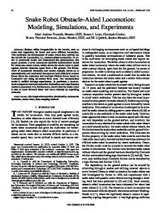
in an inertial frame. The snake robot in [29] moves only four or five modules simultaneously, so giving the position and orientation relative to the first motionless link prevents traversing through the complete structure to obtain positions and orientations in an inertial frame. The locomotion scheme in [28] is based on constant joint movement, so we have to traverse through the whole structure and hence the approach in [29] will not simplify the mathematical structure. Therefore, a virtual structure for orientation and position (VSOP) is introduced to be able to describe the kinematics of the snake robot in an inertial reference frame. Reference [28] presents a snake robot with 5 revolute 2 DOF joints. The VSOP describes the trailing link of the snake robot in an inertial reference frame by 3 orthogonal prismatic joints and 3 orthogonal revolute joints which represent the position and orientation, respectively. The joints are connected by links with no mass. By employing the VSOP in the DenavitHartenberg convention, the position and orientation of each joint is given in an inertial coordinate system. 2) A Backbone Curve (and its Reference Set): Instead of starting by finding the position and orientation of each joint directly as with the Denavit-Hartenberg convention [30], a backbone curve may be employed. The backbone curve is defined in [11] as "a piecewise continuous curve that captures the important macroscopic geometric features of a hyperredundant robot" and it typically runs through the spine of the snake robot. A set of orthonormal reference frames are found along the backbone curve to specify the actual snake robot configuration. The backbone curve parametrization together with an associated set of orthonormal reference frames is called a backbone curve reference set and allows for snake robots built from both prismatic and revolute joints [31]. The problem of determining joint angles of a robot manipulator given the end-effector position is called the inverse kinematics problem. For hyper-redundant manipulators (such as snake robots) this is a very computationally demanding task. When the backbone curve is employed, the problem is reduced to determining the proper time varying behaviour of the backbone reference set. The method of backbone curves has not been found together with modeling of dynamics, but is rather a method for abstraction and understanding of the geometric aspects of snake robot motion planning where the dynamics may be neglected. 3) Nonholonomic Constraints and Snake Robots with Passive Caster Wheels: The key to snake robot locomotion is to continuously change the shape of the robot. This is achieved by rotation and/or elongation of its joints. References [12], [14] both present kinematic approaches on how to link the changes in internal configuration to the net position change of the robot. The relation is found by utilizing nonholonomic constraints and differential geometry such as connections. Reference [14] employs Hirose’s Active Cord Mechanism Model 3 (ACM III) as an example which will be explained in the following. The first three pair of wheels of ACM III are illustrated in Fig. 4. The five joint angles φ1 , φ2 , φ3 , ψ 1 , and ψ 3 are controlled inputs. The kinematic nonholonomic constraints are realized by adding passive caster wheels on the snake robot and may be written in the form x˙ i sin (φi ) − y˙i cos (φi ) = 0
(1)
Fig. 4.
The first three links of the ACM III [14].
where (x˙ i , y˙ i ) is the velocity of the center of mass and φi is the angle of the joint which the wheels are attached to. More on nonholonomic systems are found in [32], [33]. The wheels are assumed not to slip and therefore realize an ideal version of the frictional properties of the snake skin as mentioned in Sec. II-B. A local form A of a connection provides the relation between the shape changes of the snake robot and its net locomotion: g −1 g˙ = −A (r) r˙ (2) where r is the shape variables and g ∈ SE (2) gives the overall position and orientation of the snake robot [14]. The connection provides understanding of how shape changes can generate locomotion and can even be used for controllability tests [34]. The simple form of (2) is dependent on the kinematic constraints breaking all the symmetries of the Lagrangian function which may raise dynamic constraints. This is achieved, with the ACM III as an example by using the first three segments to define the net motion of the snake robot. These segments define the path which is to be followed by the remaining segments due to the nonholonomic constraints on the wheels. As opposed to the backbone curve reference set, this modeling technique may also include the dynamics as will be described in Sec. III-B.2.e. B. Dynamics The dynamics of the snake robots presented has been derived by utilizing various modeling techniques such as the Newton-Euler formulation, Lagrange functions and geometric mechanics. For snake robots without wheels, the friction between the snake robot and the ground affects the motion of the snake robot significantly. Thus, for these snake robots, the dynamics should be modelled for locomotion patterns such as lateral undulation. For snake robots with wheels, however, the wheels greatly reduce the friction and, hence, make it possible to use a purely kinematic model of the robot. The majority of the results presented on modeling of the dynamics have therefore considered snake robots without wheels. In the following we will first give a short introduction to the notation utilized below, then we give a brief overview of a selection of the results reported on the modeling of dynamics of wheeled snake robots, and finally we present the results on snake robots without wheels. To ease the presentation of the mathematical models, a common notation for some of the material is presented which is based on [19], [35]. Denote the mass mi , length 2li and moment of inertia Ji for each link i = 1, 2, ..., n. Denote the angle θi between link i and the inertial (base) x-axis. Denote
the center of gravity (CG) of link i by (xi , yi ). Denote the unit vectors tangential ei,t ∈ R2 and normal ei,n ∈ R2 to the link i in the horizontal xy-plane. Hence, ei,t points along link i while ei,n ⊥ ei,t . Denote the velocity vi = [x˙ i y˙i ]T ∈ R2 , and tangential and normal velocity at link i vi,t = ei,t eTi,t vi and vi,n = ei,n eTi,n vi , respectively. The external forces on the CG of link i is denoted fi = T [fxi fyi ] ∈ R2 where fxi , fyi are friction forces between link i and the ground in the base frame x and y direction, respectively. Frictional forces tangential and normal to link i are denoted fi,t and fi,n with appurtenant frictional coefficients (j) (j) ci,t and ci,n , respectively, where j is used to separate coefficients between the various equations. 1) Snake Robots with Passive Caster Wheels: To keep the difference between lateral and longitudinal friction as high as possible, caster wheels are attached to the belly of the snake robot. The equations of motion of a simplified version of the snake robot used in [13] are presented in [35]. The robot is the same as the ACM-III shown in Fig. 1 except that the wheel axles are fixed. The dynamic model is derived to utilize acceleration-based control algorithms. It is assumed that the wheels do not slip sideways. A snake robot (called the SR#2) has been presented and compared to the ACM-III in [3]. The Active Cord Mechanism (ACM) modeling assumes that the wheels do not slip. This non-slippage introduces nonholonomic constraints. The SR#2 model is based on holonomic framework and is hence without the no-slip condition. The argument used against assuming no slip is that it is difficult to control the torques in the joints such that the assumption is satisfied. Simulations show the ACM-III build up an error in position while following a circular path. This is not the case for SR#2, something which makes it a more accurate model for this scenario. 2) Snake Robots without Wheels: The use of wheels decreases terrainability [19], thus wheel-less robots have an advantage. As discussed earlier, friction plays a significant role for wheel-less snake robots, hence it is necessary to model the dynamics and not only the kinematics for relatively high speed motion. An overview of the friction models employed will first be given, then a selection of dynamic models derived for snake robots without wheels will be presented. a) Friction Models: The friction models presented in literature are based on a Coulomb or viscous-like friction model and can be found, for instance, in [36]. A spring-damper model implements the ground contact force for the 3D dynamic model given in [28]. The contact force is written ½ 0 , zi º 0 (3) fNi = −k · zi − d · z˙i , zi ≺ 0 where zi is the height of link i, z˙i = dz dt , k is the constant spring coefficient of the ground, and d is a constant damping coefficient that serves to damp out the oscillations induced by the spring (d, k ∈ R). Using fNi , the friction force on link i, based on a simple, viscous-like model, is written as (1)
(1)
(4) fi = − ci,t |fNi | vi,t − ci,n |fNi | vi,n £ ¤ T The sum of forces acting on link i is fi3D = fiT fNi . The spring coefficient k needs to be set very high to imitate a solid surface. Hence, the total system is stiff and requires a very
small simulation step size to be simulated. A friction model including both static and dynamic friction properties for a 3D dynamic model is found in [37]. The 2D anisotropic viscous friction model used in [20] can be derived from (4) by setting fNi ≡ 1. In this case, we find that (5) fi = Hi vi , ·µ ¶ ¸ (2) ci,t (2) where Hi = ci,n 1 − (2) ei,t eTi,t − I2×2 , and I2×2 is a ci,n
unit matrix. The effect of rotational motion of the links is introduced in the two 2D friction models, one with viscous and one with Coulomb friction, presented in [19]. Both models are derived by integrating the infinitesimal friction forces on a link. The translational part of the viscous friction model is given by (4) with fNi = mi (i.e. not a force). The total viscous friction torque due to rotational velocity around the center of mass of link i is found to be (3) τ i = −ci,n Ji θ˙ i ,
(6)
Employing Coulomb friction as the friction model results in a more complicated, but also more accurate model. The model (4) does not include dry friction and thus the high friction forces which may arise at low velocities are not modeled. The results from the analysis of the parameters governing the shape of the snake robot during locomotion by lateral undulation were generally the same for the viscous and the Coulomb friction model in [19]. For most of the gaits simulated with the above friction models, the property ci,t < ci,n has been implemented to realize the anisotropic friction property of a snake moving using lateral undulation. It may be difficult to design a snake robot with ci,t < ci,n on a general surface. Sidewinding has been implemented with an isotropic friction model (ci,n = ci,t ) in [38] and as a purely kinematic case in [26]. Special gaits based on an isotropic friction model are detailed in [39], [40]. b) Dynamic Model with Decoupling: A five link snake robot with 1 DOF joints was modeled and controlled in [19]. The robot was built and experiments performed to validate the theoretical results. Metal skates were put on the belly to implement cti < cni . The dynamic model of the snake robot has been developed from the Newton-Euler equations resulting in two sets of equations: one for translational motion of the center of mass w of the snake robot and another for the rotational motion of the angle of each link given in an inertial frame. The final equations of motion can be decoupled into two parts: shape motion and inertial locomotion. The shape motion maps the joint torques to joint angles while the inertial locomotion relates the joint angles to the inertial position and orientation. This simplifies the analysis and synthesis of locomotion of the snake robot. To achieve decoupling, a vector of relative angles φ, where φi = θi − θi+1 , and a quantity ψ which can be thought of as "an average angular momentum" are introduced. The expressions for shape motion and inertial motion, respectively, are found to be ³ ´ ¨ θ, θ, ˙ w ˙ = Bu, (7) hs φ, ³ ´ ˙ ψ, ¨ θ, w, ˙ hi ψ, ˙ w, ¨ φ = 0 (8)
where hs (·) , hi (·) ∈ Rn are functions found in [19], θ = [θ1 · · · θn ], u are the joint torques and B is an invertible matrix. Control of the snake robot is now performed in two steps. First, the joint torques u control the shape of the robot and second the relative angles φ control the average angular momentum ψ and position w. c) Quasi-Stationary Equations of Motion: A 2D model based on the Newton-Euler formulation of a snake robot with 1 DOF revolute joints with the viscous friction model (5) is presented in [20]. Non-dimensional variables are introduced to simulate the dynamics of the snake robot. The resulting system of second order nonlinear equations which constitute the nondimensional model of the snake robot may become unstable during simulation. To aid the numerical treatment, overcritical damping is introduced by setting accelerations to zero. The result is a set of quasi-stationary first-order differential equations of motion. By employing the first-order equation for translational motion together with the friction model in short form (5) the velocity of the head of the snake robot is found to be ³Xn ´−1 Xn (rel) Hi Hi vi (9) vhead = − i=1
i=1
(rel) vi
where is the velocity of link i with respect to the head. Reference [19] gives the relationship between shape changes from joint angle deflection and the position of the CG of the snake robot (8). To investigate locomotion analytically, (9) offers an alternative approach where the direct connection between velocities of each link relative to head of the snake robot and the head velocity is given. d) Newton-Euler Algorithm: A physical and mathematical model of a snake robot with five 2 DOF joints is presented in [28]. In addition to the actual snake robot, A virtual structure of orientation and position (VSOP, see Sec. IIIA.1) is included in the dynamic model. The VSOP together with the snake robot have generalized coordinates q and generalized forces u. The Newton-Euler formulation and the VSOP perspective is employed, and the dynamic model is written as M (q) q ¨ + C (q, q) ˙ q˙ + g (q) = u + τ ext
(10)
where M is the inertia matrix, C is the Coriolis and centripetal matrix, g (·) is the vector of gravitational forces and torques, and τ ext is the vector including the external forces. The matrices are detailed in [38]. While (10) has not been employed for dynamic analysis, analytical expressions for the joint torques and head configuration of a 3D snake robot model deducted from the Newton-Euler methods are shown in [37]. The Lagrange and the Newton-Euler method are similar in that the expression obtained by the Lagrange method is found by running through the Newton-Euler algorithm once. Since the Newton-Euler algorithm deals with the mathematical model as a recursive algorithm, it is a more efficient framework for simulation than the Lagrange method for large models [36]. e) Lagrange’s Equations: Research on robots that resemble snakes are not only limited to land-based locomotion. Papers regarding anguilliform (eel-like) locomotion have also been published [21], [41]–[43]. A five link 2D snake robot (called the REEL II) with 1 DOF revolute joints, which will be used as an example in the following, has been modeled and
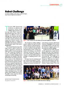
experimented on in [21]. Motion planning for such a robot consists of first building up the momentum to the snake robot and then steering the robot to its desired location. Hence, it is convenient that the mathematical model includes an explicit expression for the momentum. The model is formulated for Lagrange’s equations and is summarized in the following. The fact that the energy of the system and the frictional forces acting on the system are invariant with respect to the position and orientation of the snake robot (the system exhibits Lie groups symmetries), is exploited to simplify the mathematical model. The assumption that the joint angles are controlled directly (The same as saying that the dynamics (7) is ignored) yield two sets of resulting equations. The first equation relates the velocity of the snake robot to its internal shape changes and is similar to (2) given in Sec. III-A.3 except for the locked inertia tensor I (r) and generalized momentum vector p that have been added (we have a case of mixed constraints with both kinematic and dynamic constraints). The dynamics of the system is described by the generalized momentum equation which is the second set of resulting equations. The generalized momentum p is associated with the momentum along the directions allowed by the kinematic constraints. A thorough explanation of the equations is found in [44]. IV. S NAKE ROBOT L OCOMOTION A variety of approaches on how to make a snake robot locomote have been proposed. In most of the motion patterns or ’gaits’ used for locomotion, we find a distinct resemblance to the undulating locomotion of biological snakes or worms, but the motion patterns may be changed to compensate for the fact that the snake robots do not have the exact same anatomy as biological snakes, inchworms or caterpillars. Early studies of snake locomotion were given in [1]. Later, a mathematical description of the serpentine motion of snakes was presented [13]. An overview of gaits that have been implemented is found in Table I where we see that lateral undulation is the most common. Depending on how the snake robot is modeled and/or constructed, the mathematical expression for the gait varies. A description of the joint reference signals for lateral undulation and a short note on sidewinding will first be given, then other locomotion schemes will be discussed. A. Snake Robot Locomotion by Lateral Undulation and Sidewinding Lateral undulation is implemented as a sine-like wave propagating down the body of the snake robot from the head to the tail. Reference [13] presents a formula for such a curve called the serpenoid curve where the curvature changes smoothly. The snake robot locomotes by following the trace of the curve. The serpenoid curve is shown in Figure 5 and
Gait Concertina Lateral undulation
TABLE I OVERVIEW OF GAITS With passive wheels
Without wheels [16]a [3], [14], [15], [17], [6], [19]–[21], [28], [18], [35], [45]–[47] [41], [48] Sidewinding [26], [28] Inchworm/Caterpillar [17], [22], [29], [49] Climbing [50], [51] a Uses friction from solenoids that are lifted and lowered
y y(l) Q α s
snake spine
P (s = 1)
s direction of progress
α O
x x(l)
Fig. 5. The serpenoid curve [13]. By permission of Oxford University Press.
is a function of the distance along the curve s, the length of one quarter period of the curve l, and the winding angel along the curve αs (s, l), where α = αs (0, l). Denote the tangential ci,t and normal ci,n frictional coefficient, between link i and the ground. The winding angle αs is determined by the link length, bending angles between adjacent links and the ratio ci,t /ci,n where the ratio also gives a lower bound for αs . The curvature of the serpenoid curve is given by ³π ´ π s . (11) ρ (s) = α sin 2l 2l Except when otherwise specified, the common assumption is ci,t < ci,n . By adding a constant of turning motion c to (11), the relative reference angle for joint i is found from (11) to be (see e.g. [46]) φi = A sin (ωt + h (i) β) + γ
(12)
where A is the maximum amplitude of oscillation, β is the phase shift between adjacent links, γ determines the orientation of the snake robot, ω is the speed of the serpentine wave that propagates down the body of the snake robot and h (i) is a function that depends on the model of the snake robot, e.g. h (i) = i − 1 [19] or h (i) = i − 2 [41]. The use of γ to change the heading of the snake is discussed and two alternative turning motions are presented in [46]. For snake robots with 2 DOF revolute joints, a second reference signal for the vertical wave is needed [28]: φi,v = Av sin (ω v t + h (i) β v + β 0 ) + γ v .
(13)
The phase difference between the horizontal and vertical wave is given by β 0 . The direction of locomotion when using lateral undulation (Av = 0) is controlled by γ, while β 0 dominates the control of locomoting direction during sidewinding. The wheeled ACM III has been used as an example in [14]. The angle between adjoining links and the wheel axles at the corresponding links is set 90◦ out of phase to locomote and avoid side slip of the wheels. The ACM III model has also been used with fixed wheel axles where a Lyapunov based control method is proposed [35]. A wheeled snake robot able to move in 3D is presented in [47]. It is shown that for the robot to be controllable and observable, one needs 4 ≤ m ≤ n − 2, where m is the number of of wheels touching the ground. Some results on controllability are also given in [52]. Sinus-lifting has also been implemented [37], [45]. A 2D model incorporating a ground contact force which is a function of the curvature of the snake body is used in [37]. It is shown that the snake robot moves forward faster by sinus-lifting, than by lateral undulation.
Real snakes use obstacles such as stones or indentations in the ground to aid locomotion during lateral undulation. References [13], [53] utilize walls and large cylinders to generate propulsive forces for a wheeled snake robot. A snake robot without wheels employs push-points, such as pegs, to create the total propulsive force during a form of lateral undulation [54]. Here, the ratio between lateral and longitudinal friction is disregarded, which makes it possible to build and locomote snake robots without the friction property ci,t < ci,n , and hence without wheels. The joints are not bent to push against the pegs; instead, the snake robot has linear actuators on each side of the links that push out from the link. Sidewinding was performed with ct,i = cn,i in [38] and it was found that both γ and β 0 controls the direction of locomotion. A gait qualitatively similar to the sidewinding locomotion has also been developed in [26] for 3D motion on a flat surface. B. Alternative Approaches to Locomotion While most of the approaches to locomotion presented above rely on the tangential/normal friction property, others have explored alternative ways to locomote where either the friction model is isotropic or a purely kinematic model is used. Locomotion for a 2-link, 3-link and multi-link system with 1 DOF revolute joints are shown in [39], [40]. Dry friction forces between the links and the ground is assumed. A combination of fast and slow movements of the joints is used to move the 2-, and 3-link system to any point in the plane. With very small velocities and accelerations, the multilink system was able to move by propagating a single wave at the time consisting of 3 to 4 links forward along the snake robots body. Inchworm-like motion has been shown with [22] and without [22], [29], [49] extensible joints. While the two first references rely on slow speeds to avoid slipping, the latter pump water between the link to add weight to the parts that are not moving. This way, the ground contact force, and hence the friction, on the moving parts are reduced. Figures and descriptions of several types of gaits for 2D and 3D motion of a snake robot without wheels are given in [17]. V. D ISCUSSION AND F UTURE R ESEARCH TOPICS Research on snake robots has increased the past ten years, but there are still many challenges to face both on the modeling and control of snake robots in order to make them able to locomote intelligently through unknown terrain. We have seen in this article that various approaches to mathematical modeling of snake robots have been presented. Some focus purely on the kinematic aspects of locomotion [14], [22], [52] while others also include the dynamics [3], [15], [19], [35], [41]. Employing only the kinematic model simplifies both the model and the analysis of locomotion, and factors that contribute to locomotion have been highlighted [14], but there is still no mathematical framework to prove locomotion of a general motion pattern. Passive wheels help defend the nonslip assumption of some kinematic models, but can it may be difficult to control the joint torques such that the wheels do not slip [3], [15]. A kinematic approach to locomotion without wheels is justified by assuming low velocities and sometimes also certain friction properties (such as low friction while
gliding forwards, but high friction when pushed backwards) [22]. There are two main reasons to model a system mathematically. One is that the model can be used to investigate analytically how to control the system. The other reason is to simulate the behaviour of the system, for example for testing motion patterns. Mathematical models including the dynamics of motion yield a more accurate description of the behaviour of the system which is advantageous with respect to simulation, but the models may get very large and unwieldy. Thus, the simplicity of an analytical analysis suffers. In 2D models, certain properties of the system help to simplify the model [21], but not all of these properties persist in 3D models. In the papers presented, most models are 2D, but moving in a shattered building, for example is inherently a 3D experience. 3D models have been presented [22], [26], [47] which provide some results on controllability and observability, but without including the dynamics. During the last two years, 3D dynamic models based on the Newton-Euler equations have been presented [28], [37]. No 3D models have been found that are developed using Lagrange’s equation, and this may be a result of that the invariance used to simplify the equations in 2D are no longer valid in 3D. Mathematical expressions for the joint torques and head configuration are derived in [37], but for the gait analysis, the model has been simplified to planar movement with a varying ground contact force which affects the friction forces on each link. Hence, there are still numerous challenges in the analytical investigation of the dynamics of 3D locomotion. Regardless of the downsides of dynamic modeling, the dynamics needs to be considered in the cases where slow locomotion is unacceptable or when wheels cannot be employed due to the nature of the surface travelled on. In such cases, friction and maybe even impacts need to be considered and utilized to aid locomotion. The only impact model found in literature regarding snake robots is a linear spring-damper model [28], which results in a stiff mathematical model and thus a need to a low step length in simulations. Friction forces are modeled either by viscous or Coulomb friction, where the latter includes dry friction which is essential for some gaits [40]. The directional friction property between the belly of the snake and the ground, most often implemented on snake robots, can not always be realized for travel on a variety of surfaces. Planar locomotion utilizing differences between static and dynamic friction [40] and exploiting pegs on the ground [54] are being investigated, and there is still a great amount of research to be done in this area. Based on the above discussion, the following future research topics are proposed: 1) Develop a mathematical framework to help develop and prove general motion patterns, 2) Prove controllability and observability while including the dynamics of the snake robot, 3) Develop motion patterns that are independent of ground conditions, and 4) Find ways to better use pegs or other obstacles to improve locomotion speed. VI. C ONCLUSION A snake robot has limited payload capability, poor power efficiency and a high number of degrees of freedom. Nevertheless, the snake robot exhibits great terrainability and has the capability of inspecting narrow places. It can also be made very robust to dirt and dust by covering the robot
completely with a shell. These properties make the research on snake robots worth-while. It is hoped that this document will help promote further research on the fascinating topic of snake robots through the overview given on modeling and locomotion. R EFERENCES [1] J. Gray, “The mechanism of locomotion in snakes,” J. Exp. Biol., vol. 23, no. 2, pp. 101–120, 1946. [2] S. Hirose, “Active code mechanism no.3 "ACM III",” 2003. [Online]. Available: http://wwwrobot.mes.titech.ac.jp/robot/snake/acm3/acm3_e.html [3] P. Wiriyacharoensunthorn and S. Laowattana, “Analysis and design of a multi-link mobile robot (serpentine),” in Proc. IEEE Int. Conf. Robotics, Intelligent Systems and Signal Processing, vol. 2, December 2002, pp. 694–699. [4] M. Lewis and D. Zehnpfennig, “R7: A snake-like robot for 3-d visual inspection,” in Proc. Int. Conf. Intelligent Robots and Systems, vol. 2, Munich Germany, September 1994, pp. 1310–1317. [5] R. Worst and R. Linnemann, “Construction and operation of a snakelike robot,” in Proc. IEEE Int. Joint Symp. Intelligence and Systems, Rockville, MD USA, November 1996, pp. 164–169. [6] S. Ma, “Analysis of snake movement forms for realization of snakelike robots,” in Proc. IEEE Int. Conf. Robotics and Automation, vol. 4, Detroit, MI USA, May 1999, pp. 3007–3013. [7] S. Ma, H. Araya, and L. Li, “Development of a creeping snake-robot,” in Proc. IEEE Int. Symp. Computational Intelligence in Robotics and Automation, 2001, pp. 77–82. [8] Y. Lu, S. Ma, B. Li, and L. Chen, “Ground condition sensing of a snakelike robot,” in Proc. IEEE Int. Conf. Robotics, Intelligent Systems and Signal Processing, vol. 2, October 2003, pp. 1075–1080. [9] L. Xinyu and F. Matsuno, “Control of snake-like robot based on kinematic model with image sensor,” in Proc. IEEE Int. Conf. Robotics, Intelligent Systems and Signal Processing, vol. 1, October 2003, pp. 347–352. [10] T. Kamegawa, T. Yarnasaki, H. Igarashi, and F. Matsuno, “Development of the snake-like rescue robot "kohga",” in Proc. IEEE Int. Conf. Robotics and Automation, vol. 5, April 2004, pp. 5081–5086. [11] G. Chirikjian and J. Burdick, “A modal approach to hyper-redundant manipulator kinematics,” IEEE Trans. Robot. Autom., vol. 10, no. 3, pp. 343–354, June 1994. [12] P. Krishnaprasad and D. Tsakiris, “G-snakes: Nonholonomic kinematic chains on lie groups,” in Proc. 33rd IEEE Conf. Decision and Control, vol. 3, Lake Buena Vista, FL USA, December 1994, pp. 2955–2960. [13] S. Hirose, Biologically Inspired Robots: Snake-Like Locomotors and Manipulators. Oxford: Oxford University Press, 1993. [14] J. Ostrowski and J. Burdick, “Gait kinematics for a serpentine robot,” in Proc. IEEE Int. Conf. Robotics and Automation, vol. 2, April 1996, pp. 1294–1299. [15] S. Ma, N. Tadokoro, B. Li, and K. Inoue, “Analysis of creeping locomotion of a snake robot on a slope,” in Proc. IEEE Int. Conf. Robotics and Automation, September 2003, pp. 2073–2078. [16] Y. Shan and Y. Koren, “Design and motion planning of a mechanical snake,” IEEE Trans. Syst. Man Cyb., vol. 23, no. 4, pp. 1091–1100, July-August 1993. [17] H. Ohno and S.Hirose, “Design of slim slime robot and its gait of locomotion,” in Proc. IEEE/RSJ Int. Conf. Intelligent Robots and Systems, vol. 2, November 2001, pp. 707–715. [18] S. Ma, “Analysis of creeping locomotion of a snake-like robot,” Adv. Robotics, vol. 15, no. 2, pp. 205–224, 2001. [19] M. Saito, M. Fukaya, and T. Iwasaki, “Serpentine locomotion with robotic snakes,” IEEE Contr. Syst. Mag., vol. 22, no. 1, pp. 64–81, February 2002. [20] I. Grabec, “Control of a creeping snake-like robot,” in Proc. 7th Int. Workshop on Advanced Motion Control, July 2002, pp. 526–513. [21] K. McIsaac and J. Ostrowski, “Motion planning for anguilliform locomotion,” IEEE Trans. Robot. Autom., vol. 19, no. 4, pp. 637–625, August 2003. [22] G. Chirikjian and J. Burdick, “The kinematics of hyper-redundant robot locomotion,” IEEE Trans. Robot. Autom., vol. 11, no. 6, pp. 781–793, December 1995. [23] C. Mattison, The Encyclopaedia of Snakes. London: Cassell Paperbacks, 2002. [24] R. Bauchot, Snakes: A Natural History. Sterling Publishing Company, 1994. [25] K. J. Dowling, “Limbless locomotion. learing to crawl with a snake robot,” Ph.D. dissertation, Carnegie Mellon University, December 1997. [26] J. Burdick, J. Radford, and G. Chirikjian, “A ’sidewinding’ locomotion gait for hyper-redundant robots,” in Proc. IEEE Int. Conf. Robotics and Automation, May 1993, pp. 101–106.
[27] R. M. Murray, Z. Li, and S. S. Sastry, A Mathematical Introduction to Robotic Manipulation, 1st ed. Florida, USA: CRC Press, 1994. [28] P. Liljebäck, Ø. Stavdahl, and K. Y. Pettersen, “Modular pneumatic snake robot: 3D modelling, implementation and control,” in Proc. 16th IFAC World Congress, July 2005. [29] G. Poi, C. Scarabeo, and B. Allotta, “Traveling wave locomotion hyper-redundant mobile robot,” in Proc. IEEE Int. Conf. Robotics and Automation, vol. 1, May 1998, pp. 418–423. [30] G. S. Chirikjian, “Theory and applications of hyper-redundant robotic manipulators,” Ph.D. dissertation, California Institute of Technology, Pasadena, California, 1992. [31] G. Chirikjian and J. Burdick, “Kinematics of hyper-redundant robot locomotion with applications to grasping,” in Proc. IEEE Int. Conf. Robotics and Automation, April 1991, pp. 720–725. [32] I. Kolmanovsky and N. McClamroch, “Developments in nonholonomic control problems,” IEEE Contr. Syst. Mag., vol. 15, no. 6, pp. 20–36, December 1995. [33] A. M. Bloch, J. Baillieul, P. Crouch, and J. Marsden, Nonholonomic Mechanics and Control. Springer-Verlag, 2003. [34] S. Kelly and R. M. Murray, “Geometric phases and robotic locomotion,” J. Robotic Systems, vol. 12, no. 6, pp. 417–431, 1995. [35] P. Prautsch and T. Mita, “Control and analysis of the gait of snake robots,” in Proc. IEEE Int. Conf. Control Applications, Kohala Coast, HI USA, 1999, pp. 502–507. [36] O. Egeland and J. T. Gravdahl, Modeling and Simulation for Automatic Control. Trondheim, Norway: Marine Cybernetics, 2002. [37] S. Ma, Y. Ohmameuda, and K. Inoue, “Dynamic analysis of 3dimensional snake robots,” in Proc. IEEE/RSJ Int. Conf. On Intelligent Robots and Systems, 2004, pp. 767–772. [38] P. Liljebäck, “Modular snake-robot: Modeling, implementation and control of a modular and pressure based snake-robot,” Master’s thesis, Norwegian University of Technology and Science, Trondheim, Norway, 2004, in Norwegian. [39] F. Chernousko, “Snake-like motions of multibody systems over a rough plane,” in Proc. 2nd Int. Conf. Control of Oscillations and Chaos, July 2000, pp. 321–326. [40] Chernousko, “Modelling of snake-like locomotion,” Appl. Math. Comput., vol. 164, no. 2, pp. 415–434, May 2005. [41] K. McIsaac and J. Ostrowski, “A geometric approach to anguilliform locomotion: Modelling of an underwater eel robot,” in Proc. IEEE Int. Conf. Robotics and Automation, vol. 4, May 1999, pp. 2843–2848. [42] ——, “Motion planning for dynamic eel-like robots,” in Proc IEEE Int. Conf. Robotics and Automation, vol. 2, 2000, pp. 1695–1700. [43] J. Ayers, C. Wilbur, and C. Olcott, “Lamprey robots,” in Proc. Int. Symp. Aqua Biomechanisms, 2000. [44] A. Bloch, P. Krishnaprasad, J. Marsden, and R. Murray, “Nonholonomic mechanical systems with symmetry,” California Institute of Technology, Tech. Rep., 1995. [45] M. Mori and S. Hirose, “Three-dimensional serpentine motion and lateral rolling by active cord mechanism ACM-R3,” in Proc. IEEE/RSJ Int. Conf. Intelligent Robots and Systems, 2002, pp. 829–834. [46] C. Ye, S. Ma, B. Li, and Y. Wang, “Turning and side motion of snakelike robot,” in Proc. IEEE Int. Conf. Robotics and Automation, vol. 5, 2004, pp. 5075–5080. [47] S. Ma, Y. Ohmameuda, K. Inoue, and B. Li, “Control of a 3-dimensional snake-like robot,” in Proc. IEEE Int. Conf. Robotics and Automation, vol. 2, Taipei, Taiwan, September 2003, pp. 2067 – 2072. [Online]. Available: http://dx.doi.org/10.1109/ROBOT.2003.1241898 [48] Z. Bayraktarouglu, F. Butel, P. Blazevic, and V. Pasqui, “A geometrical approach to the trajectory planning of a snake-like mechanism,” in Proc. IEEE/RJS Int. Conf. Intelligent Robots and Systems, October 1999, pp. 1322–1327. [49] D. Rincon and J. Sotelo, “Ver-Vite: Dynamic and experimental analysis for inchwormlike biomimetic robots,” IEEE Robot. Autom. Mag., vol. 10, no. 4, pp. 53–57, December 2003. [50] M. Nilsson, “Snake robot free climbing,” in Proc. IEEE Int. Conf. Robotics and Automation, vol. 4, April 1997, pp. 3415–3420. [51] ——, “Snake robot - free climbing,” IEEE Contr. Syst. Mag., vol. 18, no. 1, pp. 21–26, February 1998. [52] J. Ostrowski and J. Burdick, “The geometric mechanics of undulatory robotic locomotion,” Int. J. Robot. Res., vol. 17, no. 7, pp. 683–701, 1998. [53] S. Hirose and Y. Umetani, “Kinematic control of active cord-mechanism with tactile sensors,” in Proc. 2nd RoMAnSy Symp., Warsaw, 1976, pp. 241–252. [54] Z. Bayraktaroglu and P. Blazevic, “Understanding snakelike locomotion through a novel push-point approach,” J. Dyn. Syst. - Trans. ASME, vol. 127, no. 1, pp. 146–152, March 2005.