2010 2nd International Asia Conference on Informatics in Control, Automation and Robotics
Quad Rotor Arial Robot Dynamic Modeling and Configuration Stabilization A.Azzam
Xinhua Wang
School of Automation Science and Electrical Engineering Beihang University Beijing, China
[email protected]
School of Automation Science and Electrical Engineering Beihang University Beijing, China
[email protected]
Abstract In this paper, we propose a nonlinear control scheme for attitude stabilization of 4_rotor vertical take_off and landing (VTOL) aerial robot known as the quad rotor rotorcraft. A nonlinear dynamic model of a 6_DOF underactuated quad rotor aerial robot is derived based on Newton-Euler formalism. The proposed controller is based upon the compensation of the Coriolis and gyroscopic torques and the use of a PD feedback structure for altitude and yaw channel and the use of backstepping based PID technique for the rotational control, where the proportional action is in terms of the Euler angels and the derivative action is in terms of the airframe angular velocity. We used optimization algorithm to get the proper design parameters values. With the compensation of the coriolis and gyroscopic torques, our controller provides asymptotic stability for our problem. Also our nonlinear control technique gives the ability to overcome the problem of non minimum phase. Simulation results are also provided to show the effectiveness of the proposed controller. Key words: Quad rotor rotorcraft, PD control, backstepping control, simplex optimization
I.
INTRODUCTION
Unmanned vehicles are important when it comes to performing certain tasks in an unaccessible and/or dangerous place. Remotely controlled outdoor and indoor robots have been successfully used for some decades. Through the last few years, a growing interest for unmanned aerial vehicles has been shown among the researchers. The design process of an unmanned VTOL vehicle that is highly maneuverable and extremely stable is very important contribution to the field of aerial robotics since it has tremendous potential applications (e.g., aircraft, spacecraft, helicopters, satellites, surface vessels, underwater vehicles, rescue missions, reconnaissance, high buildings and mountains exploring, film making, ... etc). In practical applications, the speed and position of the PVTOL unmanned aerial vehicle in space is generally controlled by an operator through a remote control system using a visual feedback from an onboard camera, while the
attitude is automatically stabilizes by onboard controller. The attitude controller is an important feature since it allows the PVTOL to implement different desired orientations and prevent the flipping over and crashing when the pilot performs the desired maneuvers. The quad rotor rotorcraft is a highly nonlinear, multivariable and underactuated system (6 DOFs and only 4 actuators). Rotorcraft has 4 propellers driven by motors. The main forces and moments acting on quad rotor are those produced by the propellers. The propellers generate a lift force that can be used to control pitch and roll angles. Total torque generated by the propeller motors causes a yaw to the body. Two propellers in the system are counter clockwise rotating and the other two propellers are clockwise rotating such that the total torque of the system is balanced (Le. approximately canceling gyroscopic effects and aerodynamic torques in stationary trimmed flight). Quad rotor rotorcraft achieves stable hovering and precise flight by balancing the forces (McKerrow, 2004). In (Pounds et aI., 2002), the control structure was based on internal linearization while in (Tayebi and McGilvray, 2004), a quaternion based PD feedback control scheme is implemented for quad rotor. In this paper a complete dynamic model of quad rotor is derived based on the work of (Koo et aI., 1998). Some of the previous works depend on pole placement of their proposed controller to achieve stability and it is a very hard way, because our system is time variant nonlinear one. So we used optimization algorithm instead of pole placement.A nonlinear control strategy is implemented for the derived 6-DOF model, constituted of translational and rotational subsystems. The controller for translational subsystem stabilizes the altitude and generates the desired roll and pitch angles to the rotational subsystem controller. The rotational controller stabilizes the quad rotor near hover. The proposed control strategy shows good results for quad rotor rotorcraft near hover. The advantage of quad rotor over conventional helicopters is that they have small rotors and can be
438 978-1-4244-5194-4/10/$26.00 ©2010 IEEE
CAR 2010
enclosed, making them safer for indoor flights. They also have higher payload capacity and better maneuverability in comparison with the conventional ones. It is also possible to achieve more stationary hovering with four thrust forces acting at a distance from the centre of gravity than with one force acting through the centre of gravity, as is the case with conventional helicopters. The main disadvantage of quad rotor is high energy requirement because of four motors . II.
PROBLEM STATEMENT
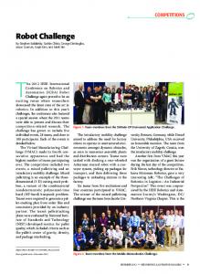
The aerial vehicle used in this work is an electric quad rotor rotorcraft, where each motor is attached to a rigid cross frame as it can be appreciated in Figure I. It is a vertical takeoff and landing vehicle (VTOL) able to move omni directionally with the ability to fly in a stationary way. In this section, we present the model of the quad rotor rotorcraft. Aerodynamic forces and moments are derived using a combination of momentum and blade element theory (Prouty, 1995; Castillo et aI., 2005) . A quad rotor has four motors with propellers. A voltage applied to each motor result in a net torque being applied to the rotor shaft, Q;, which results in a thrust, 1';. If the rotor disk is moving, there is a difference in relative velocity between the blade and air when moving through the forward and backward sweeps, which results in a net moment about the roll axis, R;. Forward velocity also causes a drag force on the rotor that acts opposite to the direction of travel , D;. The thrust can be defmed in terms of aerodynamic coefficients CT as
1; = t pACT r 2n/
(1)
where A is the blade area, p the air density, r the radius of the blade and n the angular velocity of the propeller. At hover and semi hover, it can be assumed that the thrust and drag are proportional to the square of the rotation speed of propellers. Thus the thrust and drag forces, as in (McKerrow, 2004), are given by
1; ~ KTn;
D; Ri K D n ;
(3, I) is allowed to operate independently, then the pitch angle () can be controlled along with the indirect control of motion along the same axis. Similarly when motor pair (2,4) is allowed to operate independently, the roll angle ¢ can be controlled along with the indirect control of motion along the same axis. Finally when motor pair (3, 1) is
Ez
E
Ex
Figure 1. Quad rotorhoveringsystemwith forceand torquecontrol
rotating clockwise and motor pair (2, 4) rotating counterclockwise, the yaw angle If! can be controlled. The quad rotor has now 6 DOFs . Consider the quad rotor as a single rigid body with 6 DOFs . Assuming the earth is flat and neglecting the ground effect, the equations of motion for a rigid body subject to body force F' and body moment I' if , I' E applied at the center of mass and expressed in Newton-Euler formalism, as shown in (Koo et aI., 1998), are given by:
mv" + wb x mv" = F b
(4)
Iwb +w b xlw b =r b
(2)
(3)
where KT and KD are constants and Q; is the propeller's rotation speed. In Figure. I , I represents the distance of motor from the pivot centre. ¢, () and If! represent Euler angles about x, y, z body axes, respectively. Tn (n=l, 2, 3, 4) represent the thrust force produced by each propeller. The earth fixed frame and the body fixed frame are represented by E={X; Y, Z} and B={x, y, z}, respectively. Increasing or decreasing speed of the four motors together generates the vertical motion . When motor pair
439
where m is the body total mass, Vb is the velocity vector in body axes, o} is angular velocity in the body axes, and I is the body inertial matrix . The quad-rotor is subjected to one force and three moments [4]. These force and moments represents the control inputs to quad rotor and are defmed as: Vertical force input:
». = K T
L n; 4
(5)
;=1
Pitch moment input: Roll moment input:
= K T (n~ - n;) u3 = KT(n; - n~) u2
(6)
(7)
Yaw moment input:
u4=KD(Q;+Q~-Qi-Q;)
rl =-a1z-a2 (z - zd)
(8)
The altitude of the quad rotor is stabilized by using the vertical force input u J. The desired roll and pitch angles are generated to the rotation controller, from position subsystem. The rotation controller is used to stabilize the quad rotor aerial robot near quasi stationary flight with control inputs U2, U3 and U4. From (4), the forces equations of our quad-rotor, expressed in the Inertial frame, are modeled by the following equations [2,8]
mX = (cos (b sin Bcos IfI + sin (b sin IfI)u\
(9)
mY = (cos(b sin Bsin 1fI- sin (b cos lfI)u\
(10)
mZ = u\ cosBcos(b-mg
(11)
'?r
Iy
2
¢ = (IyI-I )Blf/ + -f-U3
(13)
)¢B + -f-U4
(14)
z
x
ljJ =
(Ix;I z
x
y
z
where X and Yare the coordinates in the horizontal plane, and Z is the vertical position. lJ! is the yaw angle around the z-axis, £l is the pitch angle around the y-axis, and ¢is the roll angle around the x-axis. In our system, I, equals I y so (14) can be written as follows ljJ = Lt, u4 (15) III.
CONTROL STRATEGIES
A. Altitude and Yaw Control: In order to obtain a desired linear behavior for the vertical position, we propose the following control strategy:
where
ri
'i +mg cosBcos¢
u, = -(Kd2lf/ + K p2 (If/ -If/d)
(18)
where K d2 and Kp 2 are the deferential ad proportional gains of the PD controller and If/d is the desired yaw angle. Introducing (16)-(18) into (11) and (15) and provided that cos B cos ¢ * 0 , we obtain
i
= -';-[KdIZ +Kpl(Z -Zd)]
(19) (20)
It is very clear that by proper choosing of K d J , Kp J , K d2 and Kp 2 we can ensure a stable well-damped response in the vertical and yaw control axes. B. Position Controlles
We will take about the position control but the truth that we achive position control via the rotation control (Le. by controlling the pitch and roll angles). So first we will fmd the required roll and pitch angles to fulfill the desired speeds in both X and Y directions. Position subsystem is given by (9) and (10). Let
Xd
and
Yd
be the desired speeds in X and Y
direction respectively. Then the error between desired and actual speeds is given by,
x, -X
ex
=
ey
=Yd -Y
(21) (22)
Desired roll and pitch angles in terms of the error between actual and desired speed are thus given by,
In this section, we present our control strategies to stabilize the quad-rotor rotorcraft based on passivity and partial feedback linearization for altitude and yaw control and the Backstepping based PID control technique for rotational subsystem. Then we compare the results of the yaw control based on classical linear control PD and the backstepping based PID controller technique.
», =
where at and a2 are positive constants and representing K d J and Kp J respectively and Zd is the desired altitude. Similarly, the yaw angular position can be controlled by using
ljJ = - }z [K d2lf/ + K p2 (If/ -If/d)]
Due to small angles (), t/J and lj/, the moments equations, in the body frame, can be simplified to be as follows (j = (Iz-I x )).11; + L u (12) Iy
(17)
(16)
¢d = sin-l(u ex sin e: -u ey COSlf/)
(23)
. -1(U ex -sin¢Sinlf/]
Bd = SIn
(24)
COS¢COSlf/
where U ex and U ey are defmed as,
u ex =
K1exm u1
and
u ey
K 2e ym u1
where K} and K2 are positive constants and u/ is the desired vertical force input from altitude control.
C. Rotational Control Backstepping based PID control technique is implemented for the rotational subsystem in which the
is a stable polynomial, defme as
440
inputs U), U3 and U4 control quad rotor aerial robot at hover. In this stage we intentionally designed the yaw controller again using the backstepping based PID control technique to compare the results with the previose proposed classical linear PD controller. Let the pitch tracking error be defmed as,
e = B-Bd
Substituting by gland g will get that
J (I I- 1 J.¢ljt + I1
By differentiating the above equation we get that
+ k 2e)
In the above equation, let's consider 0 as the virtual control. Now (28) is negative if the desired virtual control
(0) d
=
iJ _!5... e d
k
I
clgl k
u
2
=
kl
2 1 (kC k + C C + ---l.....1... CkJ e---2::..[_ + _1_2 1 I k 12 k I
( kl k 2 +
(I -I J. I
zI
fjJljt-
x
(35)
y
CCkJJ I~ 2 edt + fjJ..d ]
From (35), it is clear that
"2 is a PID and its gains are,
ck + C C +---l.....1... CkJ K P = k I2 + _1_2 k 12 ( kI I
kl
(
K 1 = klk2 +
kl
CIC2k2J k and K l
In the same way we can get
gl=kle+k2e
=~(gl +clgl)
l
J
· k2 clg l 1 (k· g2 =e+-e+--=le+ k 2e+ cIgI )
g2
c2k2 Jand B = (C IC2k2 +T k Jare
A = ( CIC2
k ( CI + k: +c2 e>
e = O-Od
kl
C2 ,
positive tuning parameters. Now (33) is negative if the desired control U2 is defmed as
0
kl
(34)
-(c 2)e - (A)e - (B) Jedt
=
where CI is positive constant to increase the speed of pitch tracking loop convergence.
kl
y
kl
I
· · .. k2 clg l g2 = B-(B)d = B-Bd +-e+--
(33)
· c2 • V2 = --[gl + clg l]
(29)
is representing the pitch rate The virtual control of our quadrotor and has its own error also, that is given by,
.. ¢d]
The desirable dynamics are,
is defmed as
(0)d
-U2 -
x
- gl [clkle + clk2 Jedt]
where, (28)
=gl(kIO - klOd + k 2e)
z
y
(26)
(27)
glgl = gl (kle
k2J.
lk
k lk2 edt +
where kI and k2 are positive tuning paremters and the second term in the right hand side represents the roll error integration. Now we propose a positive defmite and time derivative negative semidefmite function VI (Lyapunov function) and considering the Lyapunov theorem,
~ =
(2 C 2J (
·
Then the first error in the backstepping design wil be,
~ =tg~
in the above equation we
V2 =gJ kl +~ e+ c i +~ e+
(25)
gl = k.e + k 2 Jedt
2
u (30)
Again, we propose another positive defmite and time derivative negative semidefmite function V2 (Lyapunov function) and considering the Lyapunov theorem,
~ =t(g~ + gi)
(31)
172 = glgl + g2g2
(32)
441
3
=
U3
and
D
(k
2
= c i +~+C2
U4
J
as follow,
J
2 1 (kC k + C C + --±......i.. ck e----!...[+k --l.......i. 3 1 34 k 3
3
J (I t, I J·Bljt-
k, ( c3 +1S+C 4 e> (
k 3k4 + C3 Ck:k 4
y
z
-
JJedt+B.
d ]
(36)
roll and pitch angles are forced to zero which permits hovering flightas in figures 2 and 3. The yaw angle reached the yaw reference input (O.lrad) and yaw rate goes to zero as in figure.4. (37)
'~~F ' •••••• 1 o
The selection of the constants Kdj , Kp j , Kd] , Kp ] , ci, C], C3, C4, C5, C6, kj , k], k3 , k4, k5,and k6 is a very hard process so we used simplex optimization algorithm of Simulink response optimization to get proper values for these constants. IV.
RESULTS AND DISCUSSION
2
3
5
6
9
10
!. : V== •: •: : •I o
1
2
3
5 Time(sec )
8
10
Figure3. Velocitycontrol in x direction
It is worthwhile to note inside the dynamic of the latter system how the angles and their time derivatives do not depend on translation components; on the other hand the translations depend on angle. Let us simulate the closed loop system with backstepping control algorithm. Drag forces will be neglected in forward and sideward flight respectively. The initial conditions used are z= I m and all other initial conditions are zero. The reference inputs to the controller are Zd=lm, X = = im! sec and 'I',FO.lrad. Although hard reference inputs are used yet the controller effectively controls roll, pitch and yaw angles of our quadrotor aerial robot in less than 4 seconds. After the velocity reference inputs (Vx and Vy) have been reached,
Y
.. •••• 0.1
!j
0.08
0.06 0.04
0.02
°0
1
2
3
4
5
6
8
9
I 10
J::~ ; ;;;;;;;; I o
1
2
4
5 lime( s ec )
7
9
10
0.05
Figure4.Yaw control using backsteppingcontrol algorithm
Figure 5 shows the response of the altitude controller with K,F4.9794 and Kp= 4.7673. Figure 6 shows the plots of quad rotor control vector output. Figure 7 shows the comparison between the yaw control and yaw rate of both PD controller and the backstepping based PIO controller.also Figure.S shows the comparison between the yaw control of both PD controller and the backstepping based PIO controller and clarify the effect of each technique to overcome the non minimum phase effect.
10
5
10
l1me(s ec )
Figure2. Velocitycontrol iny direction
442
1:~C: ::::I o
1
2
3
4
5
8
0.02 BS-P10 I
PO 0.015
1
2
3
5
8
9
/
~
I>-
~"
:
-5
-0.015
10
-0.02
:::::::, 2
3
4
5
6
7
8
9
10
1
2
3
4
5
6
7
8
9
10
1
~
! -c
0.1
1
If
O.OS
3
4
2
3
4
5
6
7
8
9
5
6
7
8
9
,:::' :::
~'~b : o
2
J
I 10
J 10
Fiure 6 Quad rotor control vector output
-----
-
-
PD controller
-
BS-PID cootroller
::A 0
0.3 li me(s ec)
04
0.5
0.6
Phillip McKerrow, "Modelling the Draganflyer fourrotor helicopter", Proceedings of the IEEE International Conference on Robotics and Automation, USA,2004. [2] Castillo, P., Lozano, R., Dzul, A.E.,. Modeling and Control of Mini-flying Machines". Springer-Verlag, New York , 2005. [3] Pounds P., Mahony R., Hynes P. and Roberts J., "Design of a Four-Rotor Aerial Robot", Proceedings of Australian Conference on Robotics andAutomation, Auckland, 2002 . [4] Qiang Lu, Yuan Z.S. and Sheng W.M.,"Nonlinear Control Systems And Power System Dynamics", Kluwer Academic, Beijing, 2001 [5] Tayebi, A., McGilvray, S.,"Attitude Stabilization of a Four-Rotor Aerial Robot". Proc . 43rd IEEE Conf. on Decision and Control, 2:1216-1221, 2004 . [1]
1
I
0.'
REFERENCES
,/
°v
I
0.1
We have presented a stabilization nonlinear control method for quad rotor rotorcraft. The modeling of quad rotor is based on Newton-Euler formalism . In the proposed control strategy , the integral of the tracking error considered in the first step of the backstepping procedure, is applied to rotational subsystem of the quad rotor aerial robot. The control law derived for nonlinear quad rotor is thus a backstepping based PID. The stabilization ability of the nonlinear controller is examined through nonlinear simulation and results indicate effectiveness of the proposed control strategy for the quad rotor aerial robot near quasi stationary flight. Also it is clear from figure .7 the superiority of the proposed nonlinear backstepping based PID controller to the linear PD controller. The nonlinear backstepping based PID controller has the ability to overcome the nonminimum phase effects in the yaw control with respect to the linear PD technique.
Time(s ec)
/
0
Figure 8 Nonminimum phase effect of both used techniques
1
~" _:~0: : , : : : : : :
/
-0.0 1
Figure 5. Altitude control of the quadrotor aerial robot
o
/
\
-0.005
Time(s ec)
~- ~b:
/
0.005
10
i E: :::: :I a
/
0.01
I,\'------==~
_j
l ~., I
~40~-o--~~---;--;--7----;-~--;;-----! 5 10 Time(s ec )
Figure 7 Comparison between yaw control of both PD controller and the backstepping based PID controller
V.
CONCLUSION
443
[6] G. Margulies,"On real four-parameter representations of satellite attitude motions," Mathematical analysis Dept. , Philco Western Lab., Palo Alto, CA, report 52, 1963. [7] Prouty R.W., "Helicopter Performance, Stability and Control", Krieger Publishing Company, Florida, 1996. [8] Celi, R., "Recent Applications of Design Optimization to Rotorcraft - A Survey," Journal of Aircraft, Vol. 36, No.1, Jan.-Feb. 1999, pp. 176 - 189. [9] Young S. S.," Robust control of a quad-rotor aerial vehicle" International Journal of Applied Electromagnetics and Mechanics, Vol. 18, 2003, pp. 103-114
[10] Abdelhamid T. and Stephen MG.," Attitude Stabilization of a VTOL Quadrotor Aircraft", IEEE transactions on control systems technology, Vol. 14, No. 3, MAY 2006
444