1790
IEEE TRANSACTIONS ON ELECTRON DEVICES, VOL. 49, NO. 10, OCTOBER 2002
Device Modeling of Ferroelectric Memory Field-Effect Transistor (FeMFET) Hang-Ting Lue, Chien-Jang Wu, Member, IEEE, and Tseung-Yuen Tseng, Fellow, IEEE
Abstract—A numerical analysis of the electrical characteristics for the ferroelectric memory field-effect transistors (FeMFETs) is presented. Two important structures such as the metal–ferroelectric–insulator–semiconductor field–effect transistor (MFISFET) and metal–ferroelectric–metal–insulator–semiconductor field–effect transistor (MFMISFET) are considered. A new analytic expression for the relation of polarization versus electric field (P–E) is proposed to describe the nonsaturated hysteresis loop of the ferroelectric material. In order to provide a more accurate simulation, we incorporate the combined effects of the nonsaturated polarization of ferroelectric layers and the nonuniform distributions of electric field and charge along the channel. We also discuss the possible nonideal effects due to the fixed charges, charge injection, and short channel. The present theoretical work provides some new design rules for improving the performance of FeMFETs.
TABLE I DEVICE PARAMETERS FOR THE SIMULATION OF FeMFET IN THE TEXT
Index Terms—Ferroelectric memory field-effect transistors (FeMFET), ferroelectric, ferroelectric random access memory (FeRAM), memory, metal–ferroelectric–insulator–semiconductor (MFIS), metal–ferroelectric–metal–insulator–semiconductor (MFMIS), modeling, one transistor (1T), transistor.
I. INTRODUCTION
T
HE ferroelectric random access memory (FeRAM) [1] has acquired much attention in recent years because they can provide nonvolatile memory operation with fast writing time. Among several possible device structures, the ferroelectric memory field-effect transistor (FeMFET) [2]–[7] having a nondestructive readout operation and high density is of vital interest. The FeMFET includes the MFISFET [2]–[5] and MFMISFET [6], [7]. In these device structures, the ferroelectric material is placed on the gate of the transistor. The stored dipole moments in the ferroelectric material can adjust the threshold voltages of an FeMFET and thus the drain current of each switching state can be discriminated and identified as a logic state in a memory. There have been many reports on the fabrications of MFISand/or MFMIS-based FETs and capacitors thus far. The systematic theoretical methods [2], [3] for the characterization and prediction of the experimental results however remain rarely seen. Manuscript received January 30, 2002; revised June 20, 2002. This work was supported by the National Science Council, Taiwan, R.O.C., under Contract NSC-90-2215-E-009-100. The review of this paper was arranged by Editor M. Hirose. H.-T. Lue and T.-Y. Tseng are with the Department of Electronics Engineering and Institute of Electronics, National Chiao-Tung University, Hsinchu, Taiwan, R.O.C. (e-mail:
[email protected];
[email protected]). C.-J. Wu is with the Department of Electro-Optics Engineering, National Huwei Institute of Technology, Huwei, Taiwan, R.O.C. Publisher Item Identifier 10.1109/TED.2002.803626.
In order to theoretically investigate the electrical characteristics of an FeMFET, Miller et al. have first proposed a mathematical model [2]. In their model, the drain current calculated by using Brews charge sheet model [10] is not suitable for an FET operated in the saturation (after pinchoff) and subthreshold regions. The model simply assumes the electric field in the ferroelectric film to be constant, independent of the channel position [2], [3]. This assumption is only valid for the case of low drain voltage. In this paper, we shall remove these limitations and propose a more relevant model to include not only the nonsaturated polarizations of the ferroelectric layer but the nonuniform distribution of the field and charge along the channel position. Systematic analyses on the electrical characteristics for MFISFET and MFMISFET in addition to the associated capacitors will be made. The material and geometric parameters of these devices used are in a wide range in order to gain some physical insight about the operation of FeMFETs. The calculation algorithm will also be described in detail so that one can easily follow. We have used 12 parameters to describe the transistor (as listed in Table I), which are the required minimum physical parameters and no other phenomenological ones are needed. The results of the electrical properties of the FeMFETs will be shown to be independent of the value of equivalent oxide thickness (EOT) of the insulator. In addition, the insulator may be fabricated in a stacked structure rather than a single layer, for the purpose of better crystallization in some experiments. With these reasons and for a more general simulation purpose, the parameter of the insulator is indicated by a single EOT instead of the dielectric ). constant and thickness (
0018-9383/02$17.00 © 2002 IEEE
LUE et al.: DEVICE MODELING OF FeMFET
1791
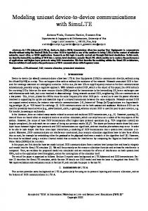
Fig. 1. P–E for the ferroelectric materials under various maximum electric fields in (1)–(6).
loop. They cannot, however, describe the nonsaturated (minor) situation. We now construct a new expression for the minor hysteresis loop within the framework of the previous model. The minor hysteresis loop is supposed to be determined by a parameter, , the maximum electric field that the ferroelectric layer may undergo. The minor hysteresis loop consists and . Since is of two branches, the maximum electric field, it is expected that and must intersect there. Together with the fact stated in [8], “existing data indicate that the derivative of the polarization with respect to the electric field, evaluated at a constant field, is independent of the amplitude of the applied signal, at least to first order,” the minor loops can be derived and given by
(4)
(5) The polarization as a function of the maximum electric field is defined by
(6)
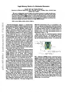
Fig. 2. Device structures and the associated sign conventions for the (a) MFISFET and (b) MFMISFET.
II. PHENOMENOLOGICAL MODEL OF POLARIZATION ELECTRIC FIELD (P–E) OF THE FERROELECTRIC CAPACITORS Miller et al. [8] have proposed a simple model to fit the experimental polarization–electric field (P–E) relationship in a ferroelectric capacitor, namely (1) where (2) (3) indicates the lower (positive-going) branch of Here, is the upper (negative-going) the P–E relation, while in the right hand side of (1) branch. The last term denotes the linear contribution of the dipole moment. Equations (1)–(3) fit well into the P–E relation of the saturated hysteresis
Two calculated minor loops of P–E are depicted in Fig. 1. The unpolarized ferroelectric material is first at the origin ). Once the applied field is increased, the dipole ( until the maximum moment will follow the curve of is reached. Then the polarization will follow electric field and along the direction indicated in Fig. 1. Equations (4)–(6) are simple and analytic and they can be used to simulate the characteristics for a ferroelectric-based device. Although they are not suitable for the case of the applied voltage being arbitrarily asymmetrical as stated in the [9], yet they are time-saving in the computer calculation. III.
–
SIMULATION OF THE CAPACITORS
The structures of MFISFET and MFMISFET together with the sign conventions are depicted in Fig. 2. For the capacitance– voltage ( – ) simulation of MFIS capacitor, the continuous boundary condition for the normal electric displacement is (7)
1792
IEEE TRANSACTIONS ON ELECTRON DEVICES, VOL. 49, NO. 10, OCTOBER 2002
where , , and are the electric fields in the ferroelectric layer, insulator, and semiconductor (Si), respectively. We can igin (7) because it is much smaller than the dipole monore . Gauss’s law gives , where ment is the space charge (per unit area) in the semiconductor is the surface band bending potential. Equation (7) can and then be rewritten as
IV. SIMULATION OF DRAIN CURRENT OF FEMFETS The drain current is calculated by using Pao and Sah’s double integral [11], namely
(15)
(8) (9) The corresponding voltage drops in the ferroelectric layer and and , respectively. The space charge density insulator are is given in [10]. The total gate voltage is given by (10) Assuming the unpolarized ferroelectric film is first at the origin ), then the dipole moment will follow . ( or and Given the maximum writing gate voltage, solving, with the help of Newton’s method, (8)–(10), one can as find the corresponding surface band bending potential in the ferroelectric well as the maximum electric field is determined, two branches layer. Once and in (4) and (5) are explicitly determined. Repeatedly solving (8)–(10) by sweeping gate voltage from to and using , then , and as a function of gate voltage can be obtained. Similarly, one can and by sweeping from to together find , . The reason for the direction will be further with discussed in Section V. The capacitance, obtained from the series combination of the multilayered capacitors, is expressed as
, is the intrinsic carrier conwhere is described in Table I. Here, is the centration, and electric field at the insulator/semiconductor interface given in [11]. The double integral over the band bending potential and the channel potential includes the integration over the width of depletion region and the channel length. The channel potential is the relative change of the electron quasi-Fermi potential along the channel position with respect to the source. In (15), both drift and diffusion currents have been considered and consequently can be used to investigate the drain current for an FeMFET operating in all possible regions such as sub-threshold, triode and saturation. In addition, the electric field and surface band bending potential are assumed not to be constant along the channel, which appears to be more relevant than the previous models [2], [3]. For an MFISFET, the gate voltage is given by (16)
where (17) where
(11) where (12) (13) is the capacitance of semiconductor given in [10]. and As for MFMIS capacitor in Fig. 2(b), the area of ferroelectric is different from that of the insulator. Then (8) should be modified as (14) Equations (11)–(13) describe the capacitance of semiconductor at low frequency. However, the capacitance at high frequency does not satisfy this relation at strong inversion. At high frequency, the generation rate of the charge carriers from the depletion region can not follow the rapid change of the applied signal and consequently the capacitance remains at the minimum value. Since the ordinary – is measured at high frequency, we constrain the capacitance to the minimum value at the strong-inversion condition.
(18)
or for or , respectively. Here is the same as that in Section II for the capacitors. Equations and by Newton’s (16) and (17) can be used to solve for and drain voltage can be method. The gate voltage varied arbitrarily to obtain the desired current-voltage ( – ) must be sufficiently relationship. Note that the value of . In the case such that the large to ensure condition of no inversion is produced in the semiconductor surface, FeMFET then will be operated in the cutoff region, which is of no interest to us here. The electric field, surface band bending and channel potentials as a function of the channel position can be calculated based on the original derivation of (15) [11]. With the fact that the drain current is unchanged at every channel position, , we can and
LUE et al.: DEVICE MODELING OF FeMFET
1793
Fig. 3. C –V simulations of MFIS capacitor at various applied biases. The device parameters are defined in Table I. The inset shows the corresponding memory window as a function of applied bias.
integrate the drain current over the channel position. With the aid of the change of variable we then have
(19) instead of . where the drain voltage is integrated to It seems to be a tedious task to solve (19) because it is an integral equation. In fact, without any additional numerical calculation there is a simple way of directly converting the plot to the plot. Note that the channel position in (19) is more easily solved for a given channel potential because the right-hand side of (19) is simply the drain current if the drain . Therefore, if the plot is first calcuvoltage is from 0 to , then lated by changing the drain voltage can be simply converted to whereas just corresponds to the channel potential at this bias con, the corresponding , and dition. Upon getting the are readily determined according to (16)–(18). As for the MFMISFET, some different calculation procedures must be done because the floating metal gate will make the uniform in the longitudinal voltage across the ferroelectric direction. As shown in Fig. 2(b), an MFMISFET can, in effect, be treated as a series of an MOSFET and an MFM capacitor. Thus by separately investigating the behaviors for these two devices enable us to analyze the characteristics of an MFMISFET. At a low drain voltage, the stored charges in MOSFET are closely equal to those in MOS capacitor. In this case, (9) and (14) can be employed to determine the gate voltage of MOSFET and the drain current may be found from (15). V. NUMERICAL RESULTS AND DISCUSSION The simulations to be done are for both the capacitor and transistor. The device and material parameters used in the present study are listed in Table I. The EOT of the insulator is set to be 4 nm and the ferroelectric is chosen to have a moderate polarization in order to obtain a suitable memory window at the low operation voltages.
Fig. 4. Memory window as a function of applied bias of MFIS capacitor for 5=6 and (b) various " . The (a) various P with a constant ratio of P =P other parameters are the same as Table I.
=
In Fig. 3, we plot the – memory window for an MFIS capacitor. The window is opened wider as the bias voltage is increased, reaching a saturated value for a larger applied bias as displayed in the inset of Fig. 3. The memory window width is defined as the flat-band voltage shift of the two aligned directions of the polarizations. At flat-band condition, and then both and the polarization of ferroelectric film are equal to zero according to (11) and(12). Thus the flat-band gate . The maxvoltage is simply the voltage in ferroelectric, , imum memory window at large bias can be calculated by is the electric field with zero polarization. Accordwhere ingly, the maximum memory window under large applied bias can then be derived as (20) Equation (20) agrees with the maximum value obtained in the inset of Fig. 3. Although it is common to recognize that the hysteresis direction for – curve should follow the direction in Fig. 3, its physical reason however is rarely given thus far. We now give ), an explanation on it. If one applies a writing voltage ( then the electric field generated in the ferroelectric and the insulator should be negative-valued according to the sign convention in Fig. 2. The polarization will then follow the lower branch based on the description in Section II. At the flat-band condition, the polarization is zero and the corresponding electric field is positive-valued. Hence the flat-band gate voltage is positive. Similarly, the flat-band gate voltage is negative for a pos). Consequently, the hysteresis itive writing voltage ( loop will trace the clockwise direction as demonstrated in Fig. 3. Likewise, the hysteresis loop will trace counterclockwise direction for an -type substrate. Shown in Figs. 4–6 are the memory windows as a function of bias voltage at various material parameters for an MFIS caand pacitor. Figs. 4(a), (b) and 5(a) show the effect of , EOT on the memory window, respectively. The results imply
1794
Fig. 5. Memory window as a function of applied bias of MFIS capacitor at different values of (a) EOT of insulator and (b) P at the condition of a constant value of P . The other parameters are the same as Table I.
Fig. 6. Memory window as a function of applied bias of MFIS capacitor for various values of (a) E and (b) t . The other parameters are the same as Table I.
that the decrease in , and EOT is necessary for capacitance matching of the ferroelectric and insulator layers so that the voltage drop in the ferroelectric layer can be increased to drive the ferroelectric into larger minor loop. Fig. 5(b) shows the memory window versus bias voltage at various values of for a fixed . The memory window is enhanced with increasing . Several literatures [5] have stated that a small polarization C cm ) is sufficient to obtain the memory window. ( We think that this assumption is incorrect because a small value of would result in the linear-like P–E curve, leading the ferroelectric to behave closely to the paraelectric phase. The memory C cm is very small, as indicated in window for , or equivalently Fig. 5(b). Therefore, increasing the ratio obtaining a square-like hysteresis loop, is essential for obtaining a large memory window. Fig. 6 illustrates the effects of coercive field and thickness of ferroelectric layer on the memory window. Larger values in and generally increase the memory windows at the same writing voltage but the writing voltage should be increased to obtain the saturated memory window. Although increasing
IEEE TRANSACTIONS ON ELECTRON DEVICES, VOL. 49, NO. 10, OCTOBER 2002
Fig. 7. C –V and I –V simulations of MFIS capacitor and MFISFET. The device parameters are given in Table I. The direction of memory window is also shown here.
and enhance the memory window, the devices are operated in a smaller minor hysteresis loop at low operation voltages. We believe the ferroelectric thin film in the saturated polarization is more stable (such as retention characteristics) than that in a minor loop. Therefore, certain trade-off should be made to optimize the material parameters. curve Both – relationship of MFIS capacitor and – of MFISFET are shown in Fig. 7 for the purpose of comparison. The drain current shows a similar memory window to the – curve. The results shown here indicate that the threshold voltages of these two states are effectively separated by the two directions of polarization in the ferroelectric and then can be identified as two states: “ON “ and “OFF”. In order to have a better for an FeMFET is shown sense margin, a suitable choice of ON OFF is in Fig. 7 in which the drain current ratio larger than 10 , suitable for memory operation. Reported studies in the literatures mostly focused only on MFIS capacitors because they are easy to fabricate and useful for material characterization. For MFIS capacitor, a suitable must be selected so that the difference in reading voltage for MFIS capacitance is large, as seen in Fig. 7. However, capacitor is different from that for FeMFET. Therefore, it is worthy of mentioning that if measurements such as retention , one then and fatigue issues are carried out with a defined should note that the measured results for both MFIS capacitor and FeMFET may be different because of their distinct values . in Fig. 8 demonstrates the drain current as a function of the drain voltage for both ON- and OFF-state. We can see that the drain current of OFF-state is less than that of ON-state at the same bias condition. A simple insight can be gained from this figure. The threshold voltage of ON-state is smaller than that of OFF-state V by about 1 V, namely the drain current of ON-state at V. Likewise, the drain is close to that of OFF state with V (ON) is close to that at V (OFF). current at Fig. 9 shows the drain current versus gate voltage at various 10 V. The memory window of the writing voltages of 3 V drain current increases with increasing writing voltage, which is similar to – curves indicated in Fig. 3. The inset is the corresponding P–E curve of the ferroelectric layer for each state.
LUE et al.: DEVICE MODELING OF FeMFET
Fig. 8. I -V simulations of MFISFET for the ON and OFF states with various V . The device parameters are given in Table I.
Fig. 9. I -V simulations of MFISFET for various writing voltages, V . The device parameters are given in Table I. The inset shows the corresponding P–E relations of the ferroelectric material.
The results indicate that a larger writing voltage would enhance the polarization to a larger minor hysteresis loop. The channel potential (or electron quasi-Fermi potential), surand are shown face band bending, space charge density, in Figs. 10–12. Fig. 10 shows the results of channel potential, in which we employ the plot of drain current versus drain bias in the inset. The maximum drain voltage is taken to be high (15 V) to clearly illustrate the after pinchoff (or saturation region) behavior. The band bending and channel potential generally increase from the source to drain. When the drain voltage is the threshold voltage), is larger than about - (where the channel becomes “pinchoff” and the band bending is constant, as shown in Fig. 11. The space charge density near the drain attains a very small value and the depletion region mainly contributes to the remnant space charges. As seen in Fig. 10, the electron quasi-Fermi potential ( ) drops pronouncedly from the drain to the pinchoff point. This causes a large gradient in the quasi-Fermi potential and it will compensate the small space charge density and keep the drain current constant. In Fig. 12, and decrease from the source to it is indicated that both will decrease to a very small value after pinthe drain. The . In the calcuchoff while there is still a remanent value of
1795
Fig. 10. Channel potential V as a function of the channel position for various drain voltages of MFISFET. The inset shows the plot of I -V at V 4V for the OFF state in Fig. 8.
=
Fig. 11. Surface band bending and Surface charge density Q as a function of the channel position for various drain voltages of MFISFET.
Fig. 12. Voltage drop across the ferroelectric layer V and insulator layer V as a function of the channel position for various drain voltages of MFISFET.
lation of Miller et al. [2], the voltages in the insulator and the ferroelectric have been assumed to be constant for convenience. This assumption would lead to a large deviation at a large drain voltage. However, in our model here, we remove this limitation and the distributions of voltages are calculated as well.
1796
IEEE TRANSACTIONS ON ELECTRON DEVICES, VOL. 49, NO. 10, OCTOBER 2002
VI. OTHER POSSIBLE EFFECTS A. Fixed Charges For an MFIS structure, the fixed charges may reside at the interface of ferroelectric/insulator or of insulator/semiconand ductor. Denoting respectively the fixed charges as , Gauss’s law then gives (21) and (22)
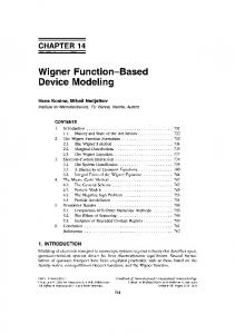
Fig. 13. Memory windows as a function of applied bias of MFMIS capacitor with various area ratios A =A . The other parameters are the same as Table I.
and , the voltages across the With the existences of and , respecinsulator and ferroelectric should change to tively. Although (22) cannot be solved in an analytical form, we can expand the solution in the first —order term and the total shift in the gate voltage due to the fixed charge is then given by
(23) B. Charge Injection
Fig. 14. I –V simulations for MFMISFETs with various area ratios A =A . The other device parameters are given in Table I. The inset is the corresponding C –V relation of MFMIS capacitors with the same A =A as in MFMISFETs.
For MFMIS capacitor, the memory windows increase with , as shown in Fig. 13. For a small decreasing area ratio, value in area ratio, the memory window increases with applied bias and attains the maximum memory window rapidly. Fig. 14 displays the – of MFMISFET and – of MFMIS capacitor for various area ratios at the writing voltages of 5 V. The memory window increases from 1 V to 1.7 V as the area ratio decreases from 1 to 0.2. The MFMIS structures with small area ratio can easily drive the ferroelectric layer to saturated polarization, which is more stable than a minor loop and is expected to have a longer retention time [6], [7] and better repeatability of threshold voltage during switching. However, the accumulation capacitance and the drain current decrease when the area ratio is decreased. This phenomenon is due to the decrease in total gate capacitance of the MFMIS structure that arises from the decrease of area of MFM, as shown in the inset of Fig. 14. The decreasing drain current effectively reduces the current ON/OFF ratio in spite of the increasing memory window, which is a drawback of the device performance. The device designers, therefore, should make certain tradeoffs between the memory window and the drain current when the area ratio decreases.
In recent developments of MFIS structures there are many high dielectric constant materials for the insulators. However, with their small bandgaps and polycrystalline structures, they often have large leakage currents and low breakdown voltages. If the device parameter is not carefully designed, the applied voltage mostly lies in the insulator rather than in the ferroelectric film, causing a large leakage current or even breakdown. In addition, the interdiffusion problems often generate a large density of trap states, in which the charges may be stored. These effects cause charge injection, which is similar to the operation of flash memory. For example, if a large and negative gate voltage will be generated is applied to MFIS capacitor, a positive due to the leakage currents in the insulator, leading to a negative shift (23) in flat-band voltage. Similarly, a large and positive , producing a positive gate voltage will induce a negative shift in flat-band voltage. Note also that this charge injection can cause a hysteresis loop but with a reverse direction in the ferroelectric memory hysteresis loop. Accordingly, the charge injection will reduce the ferroelectric memory window or even results in the wrong hysteresis direction. C. Short-Channel Effect In Section IV, the current-voltage relationship is calculated from Pao and Sah’s double integral. This formula is derived on the basis of the gradual channel approximation, in which the transverse electric field is much greater than the longitudinal one. However, for a short channel device, the influence of source/drain region on the channel and the effect of velocity saturation become important. The overall short channel effects will eventually reduce the drain current that is less than the value estimated in Section IV and increase the subthreshold slope. However, we believe the threshold voltage change between the two polarization states are still close to the estimated using our
LUE et al.: DEVICE MODELING OF FeMFET
method, at least in the first order. There also exist many complicated effects. For example, the thickness of ferroelectric film incorporated in FeMFET is often several thousands of angstroms, which is comparable to the channel length if submicron transistor is fabricated. Therefore, the fringing electric fields exist outside the gate area and this effect in turn reduces the gate control capabilities of the transistors. This similar effect has been proposed by Chen et al. [12] for the transistors made of highgate dielectrics. VII. CONCLUSION In summary, some detailed numerical analyses of MFISFET, MFMISFET, and the associated capacitors have been made for the various material and device parameters. We have presented a new simple and analytical P–E relation for the ferroelectric material, including the nonsaturated polarization. Based on this analytical formula along with Pao and Sah’s double integral for the drain current, the electrical characteristics of the above devices can be investigated. First, we have successfully simulated the – memory windows at various applied biases. A simple and clear explanation on the direction of the memory window is also given. Second, the nonuniform distributions of the field and charge along the channel position of the FeMFETs have been taken into account from Pao and Sah’s double integral. The drain current of the FeMFETs operated in all possible regions except the cut-off region can be calculated by this way. Third, other possible effects such as fixed charge, charge injection and the short channel effect are also addressed in the present study. For the MFIS and MFMIS structures, we have found some useful design rules for improving the device performance: Deand , increasing ratio and reducing EOT creasing of the MFMIS structures are the of the insulators and important factors to obtain a saturated memory window at a low and may also result in a operation voltage. Increasing larger memory window, while the voltage required to drive the ferroelectric into saturated polarization is higher. In addition to the memory window, other issues should also be considered. For of the MFMIS example, decreasing and , reducing will reduce the drain current and structures and increasing then the current ON/OFF ratio is decreased. Care must be taken to avoid possible breakdown or charge injection of the insulator due to the small thicknesses and high voltage drops across them. Besides, it is suggested to operate the FeMFETs in saturated polarizations for better retention characteristics. Therefore to optimize the device performances, certain tradeoff between these parameters should be made. If some clear device specifications are given, the present simulation method can provide the optimization of the device parameters. REFERENCES [1] A. Sheikholeslami and P. G. Gilak, “A survey of circuit innovations in ferroelectricrandom-access memories,” Proc. IEEE, vol. 88, pp. 667–689, 2000. [2] S. L. Miller and P. J. McWhorter, “Physics of the ferroelectric nonvolatile memory field effect transistor,” J. Appl. Phys., vol. 72, no. 12, pp. 5999–6010, 1992. [3] M. Ullmann, H. Goebel, H. Hoenigschmid, and T. Hander, “A BSIMS3v3 and DFIM based ferroelectric field effect transistor model,” IEICE Trans. Electron, vol. 83, no. 8, pp. 1324–1330, 2000.
1797
[4] E. Tokumitsu, R. Nakamura, and H. Ishiwara, “Nonvolatile memory operation of metal—Ferroelectric—Insulator—Semiconductor (MFIS) FETs using PLZT/STO/Si(100) structures,” IEEE Electron Device Lett., vol. 18, pp. 160–162, Apr. 1997. [5] K. H. Kim, J. P. Han, S. W. Jung, and T. P. Ma, “Ferroelectric RAM (FEDRAM) FET with metal/SrBi Ta O =SiN/Si gate structure,” IEEE Electron Device Lett., vol. 23, pp. 82–84, Feb. 2002. [6] E. Tokumitsu, T. Isobe, T. Kijima, and H. Ishiwara, “Fabrication and characterization of metal—Ferroelectric—Metal—Insulator—Semiconductor (MFMIS) structures using ferroelectric (Bi, La) Ti O films,” Jpn. J. Appl. Phys., vol. 40, pp. 5576–5579, 2001. [7] E. Tokumitsu, K. Okamoto, and H. Ishiwara, “Low voltage operation of nonvolatile metal-Ferroelectric-Metal-Insulator-Semiconductor (MFMIS)-Field-Effect-Transistors (FETs) using Pt/SrBi Ta O =Pt=SrTa O =SiON/Si structures,” Jpn. J. Appl. Phys., vol. 40, pp. 2917–2922, 2001. [8] S. L. Miller, R. D. Nasby, J. R. Schwank, M. S. Rodger, and P. V. Dressendorfer, “Device modeling of ferroelectric capacitors,” J. Appl. Phys., vol. 68, no. 12, pp. 6463–6471, 1990. [9] S. L. Miller, J. R. Schwank, R. D. Nasby, and M. S. Rodger, “Modeling of ferroelectric capacitor switching with asymmetry nonperiodic input signals and arbitrary initial conditions,” J. Appl. Phys., vol. 70, no. 5, pp. 2849–2860, 1991. [10] S. M. Sze, Physics of Semiconductor Devices, 2nd ed. New York: Wiley, 1983, ch. 7 and 8. [11] Y. Taur and T. H. Ning, Fundamentals of Modern VLSI Devices. Cambridge, U.K.: Cambridge Univ. Press, 1998, ch. 3. [12] B. Cheng, M. Cao, R. Rao, A. Inani, P. V. Voorde, W. M. Greene, J. M. C. Stork, Z. Yu, P. M. Zeitzoff, and J. C. S. Woo, “The impact of high-k gate dielectrics and metal gate electrodes on sub-100 nm MOSFETs,” IEEE Trans. Electron Devices, vol. 46, pp. 1537–1544, July 1999.
Hang-Ting Lue was born in Hsinchu, Taiwan, R.O.C., in 1975. He received the B.S. and M.S. degrees in physics from National Tsing Hua University (NTHU), Hsinchu, Taiwan, in 1999. He is currently pursuing the Ph.D. degree in electrical engineering from National Chiao Tung University (NCTU), Hsinchu. His specialties include quantum mechanics, electrodynamics, computer programming, semiconductor device physics and processing, microwave circuit design, and measurement techniques. His current research is focused on the application of ferroelectrics in microwave circuits, device modeling and fabrication of the ferroelectric random access memory (FeRAM), and the circuit modeling and de-embedding techniques of RFCMOS. He is going to be a member of the Emerging Central Laboratory, Macronix International Company, Ltd, Taiwan, R.O.C.
Chien-Jang Wu (M’01) was born in Yunlin, Taiwan, R.O.C., on March 1, 1962. He received the B.S. degree in electronics engineering, the M.S. degree in electro-optics engineering, and the Ph.D. degree in solid-state electronics, all from National Chiao-Tung University (NCTU), Hsinchu, Taiwan, in 1985, 1990, and 1996, respectively. He was a Liquid-Crystal-Display Design Engineer, Seiko Epson, Taipei, Taiwan, from 1990 to 1991. He was also a Telecommunication Hardware Engineer with TranSystem, Inc., Hsinchu, from 1991 to 1992. In addition, he was an EMC, EMI, and Telecommunication Certification Engineer at the Electronic Test Center (ETC), Taipei, in 1992. In 1993, he began to work toward his doctoral degree at NCTU, where his research was in the theory of microwave superconductivity and vortex dynamics. He later was briefly associated with the Department of Physics, National Sun Yat-Sen University, Kaohsiung, Taiwan, before joining National Huwei Institute of Technology, Huwei, Taiwan, in August of 1997, where he is now an Associate Professor in the Department of Electro-Optics Engineering. His current research interests include electromagnetic and microwave theory, vortex dynamics and microwave superconductivity, and semiconductor device modeling and simulation. Dr. Wu is a member of the IEEE Microwave Theory and Techniques Society (IEEE MTT-S).
1798
Tseung-Yuen Tseng (SM’94–F’02) received the Ph.D. degree in electroceramics from the School of Materials Engineering, Purdue University, West Lafayette, IN, in 1982. Before joining National Chiao-Tung University, Hsinchu, Taiwan, R.O.C., in 1983, where he is a now a Professor in the Department of Electronics Engineering and the Director of the Institute of Electronics, he was briefly associated with University of Florida, Gainesville. His professional interests are ferroelectric thin films and devices, electronic ceramics, ceramic sensors, and high-temperature ceramic superconductors. He has published more than 240 technical papers. Dr. Tseng was elected Fellow of the American Ceramic Society for “his notable contributions to the ceramic arts and sciences” in 1998. He was the Recipient of the Distinguished Research Awards of the National Science Council, R.O.C., from 1995 to 2000, the Distinguished Contributions Award from the Chinese Ceramic Society in 1999, and the Distinguished Electrical Engineering Professor Award from the Chinese Electrical Engineering Society in 2000. He is a registered Professional Engineer in Taiwan.
IEEE TRANSACTIONS ON ELECTRON DEVICES, VOL. 49, NO. 10, OCTOBER 2002