... Rolla, MO 65409 USA (e-mail: waleed@umr. edu). Digital Object Identifier 10.1109/TVLSI.2007.903945. TABLE I. DUAL-RAIL ENCODING. Fig. 1. THmn gate.
IEEE TRANSACTIONS ON VERY LARGE SCALE INTEGRATION (VLSI) SYSTEMS, VOL. 15, NO. 10, OCTOBER 2007
1155
Special Section Transactions Briefs DFT Techniques and Automation for Asynchronous NULL Conventional Logic Circuits
TABLE I DUAL-RAIL ENCODING
Venkat Satagopan, Bonita Bhaskaran, Waleed K. Al-Assadi, Scott C. Smith, and Sindhu Kakarla
Abstract—Conventional automatic test pattern generation (ATPG) algorithms fail when applied to asynchronous NULL Convention Logic (NCL) circuits due to the absence of a global clock and presence of more stateholding elements, leading to poor fault coverage. This paper presents a design-for-test (DFT) approach aimed at making asynchronous NCL designs testable using conventional ATPG programs. We propose an automatic DFT insertion flow (ADIF) methodology that performs scan and test point insertion on NCL designs to improve test coverage, using a custom ATPG library. Experimental results show significant increase in fault coverage for NCL cyclic and acyclic pipelined designs.
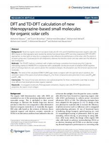
Fig. 1. THmn gate.
Index Terms—Automated design-for-test (DFT), global feedback, local feedback, NULL Convention Logic (NCL), scan insertion.
I. INTRODUCTION Asynchronous circuits fall into two main categories: delay-insensitive and bounded-delay models. Delay-insensitive paradigms, like NULL Convention Logic (NCL) [1], assume that delays in both logic elements and interconnects are unbounded, although they assume that wire forks within basic components, such as a full adder, are isochronic [2], meaning that the wire delays within a component are much less than the logic element delays within the component, which is a valid assumption even in future nanometer technologies. Testing asynchronous circuits has been a major challenge compared with their synchronous counterparts due to the fact that existing automatic test pattern generation (ATPG) tools have been developed to support clock-based-type circuits [3], [4]. NCL uses a delay insensitive, self-timed paradigm to achieve synchronization by means of handshaking, leading to the presence of asynchronous feedback paths, which in turn pose a serious problem for ATPG programs. Analysis of NCL fault coverage using existing ATPG tools reveals two important causes for fault degradation: 1) untestable faults in feedback paths and 2) unobserved faults in paths propagating through many logic levels. In this paper, we propose an automatic design-for-test (DFT) insertion flow (ADIF) methodology to enhance testability by inserting test points (TPs) and scannable observation latches (SOLs). A custom ATPG library of NCL primitive gates has been designed, which is used in conjunction with our ADIF methodology. Experimental results on several NCL circuits are included to show the validity of the proposed ADIF methodology. This paper is organized as follows. Section II overviews the NCL paradigm. Section III reviews the previous work on testing NCL circuits. Section IV presents the developed ADIF methodology. Section V compares the fault coverage results of the proposed techniques applied to various multipliers and a 72+32 2 32 MAC and Section VI provides conclusions and directions for future work. Manuscript received September 2, 2006; revised April 18, 2007. The authors are with the Department of Electrical and Computer Engineering, University of Missouri–Rolla, Rolla, MO 65409 USA (e-mail: waleed@umr. edu). Digital Object Identifier 10.1109/TVLSI.2007.903945
Fig. 2. Gate-level model of TH23 gate.
II. NCL OVERVIEW NCL provides an asynchronous design methodology by incorporating data and control information into one mixed path, so there is no need for worse case delay analysis and control path delay matching [1]. NCL relies on symbolic completeness of expression to achieve selftimed behavior. Traditional Boolean logic is not symbolically complete, since the output of a Boolean gate is only valid when referenced with time. NCL eliminates this problem of time-reference by employing dual-rail or quad-rail signals. A dual-rail signal consists of two mutually exclusive wires 0 and 1 , which may assume any value from the set {DATA0, DATA1, NULL}, as shown in Table I. Similarly, a quad-rail signal consists of four mutually exclusive wires 0 , 1 , 2 , and 3 , which may assume any value from the set {DATA0, DATA1, DATA2, DATA3, NULL}. NCL uses threshold gates with hysteresis for its composable logic elements. Such an operator consists of a set condition and a reset condition that the environment must ensure are not both satisfied at the same time. If neither condition is satisfied, then the operator maintains its current state. One type of threshold gate is the THmn gate, where 1� � as depicted in Fig. 1. THmn gates have inputs. At least of the inputs must be asserted before the output will be asserted, which is the gate’s set condition. Because NCL threshold gates are designed with hysteresis, all asserted inputs must be deasserted before the output will be deasserted, which is the reset condition [5]. Thus, any threshold gate can be represented in terms of its set and reset condition: Z = f + (g � Z0 ), where is the set condition, is the complement of
D
Q Q
m
Q
D
D
Q
Q
m n n
n
f
1063-8210/$25.00 © 2007 IEEE Authorized licensed use limited to: University of Missouri. Downloaded on January 21, 2009 at 16:21 from IEEE Xplore. Restrictions apply.
g
1156
IEEE TRANSACTIONS ON VERY LARGE SCALE INTEGRATION (VLSI) SYSTEMS, VOL. 15, NO. 10, OCTOBER 2007
Fig. 3. NCL system framework.
the reset condition, and Z 0 is the previous value of the output Z . Most threshold gates employ gate internal feedback paths (GIFs) in order to satisfy the hysteresis condition, represented by g � Z 0 in the previous equation. As an example, consider the TH23 gate whose output Z is asserted when at least two of its three inputs (i.e., A, B , C ) are asserted, and remains asserted until all inputs are deasserted. The TH23 gate is represented by Z = AB + BC + AC + ((A + B + C ) � Z 0 ), and is depicted in Fig. 2. NCL pipelines can be categorized as cyclic or acyclic based on the presence of feedback in the datapath. A cyclic pipeline has a feedback loop in its datapath, whereas an acyclic pipeline does not have datapath feedback. Both cyclic and acyclic NCL pipelines employ feedback in their handshaking completion paths. As seen in Fig. 3, each stage in a pipelined NCL system consists of three components: combinational logic, registration, and completion logic, all consisting of threshold gates. In an NCL system, the DATA wavefront and NULL wavefront are applied alternately [1]. The NCL registers interact with one another using handshaking signals to ensure that successive DATA wavefronts are separated by a NULL wavefront. When the register output is DATA (i.e., not NULL), request for NULL (rf n or logic 0) is generated on its Ko output; and vice versa, when the register output is NULL, request for DATA (rf d or logic 1) is generated on its Ko output. These handshaking signals constitute the global feedback paths (GFPs) that exist between registration stages. III. PREVIOUS WORK Several DFT methods for asynchronous delay insensitive circuits have been reported. Kang et al. [6] proposed a new scan design with low overhead for asynchronous micropipeline circuits to efficiently detect stuck-at and delay faults. A partial-scan technique for targeting delay faults for clockless systems was demonstrated in [7]. Kondratyev et al. [3] focused on test methodologies for acyclic and cyclic NCL pipelines. In [3], acyclic pipelines are converted into combinational logic by removing the registers and completion detection through a process of fault grading. The stuck-at faults in the completion circuitry are easily tested and can, therefore, be ignored. Similarly, the faults in the registration stages are eliminated by fault collapsing using dominance. Every threshold gate in the remaining combinational logic is then replaced by equivalent Boolean gates implementing the same logic function. This method yielded a good correlation between the actual and the equivalent designs, since the actual designs were found to be 100% testable in most cases. Cyclic pipelines are more complex to test. A partial scan methodology wherein the designer specifies the points where the scan latches are to be inserted was proposed to test cyclic pipelines. This method targets the level sensitive scan design (LSSD) style clocking with two-phased nonoverlapping clocks. A single register in an acyclic pipeline, identified as a scan candidate by the designer, would be replaced by its equivalent scan version. This technique was tested on circuits by using conventional ATPG tools to yield high test coverage [3]. While the work by Kondratyev et al. presents proof for the supposition that an NCL gate’s reset condition is always 100% testable, and
Fig. 4. Insertion of control point and XOR tree.
hence can be excluded while running testability analysis, it would be very useful to be able to determine the fault coverage of the circuit as a whole, using conventional ATPG tools, rather than only the set condition. This would also eliminate the additional process of padding the generated test patterns with NULL patterns to test the original pipeline. Furthermore, a stuck-at fault in a gate internal feedback path could result in: 1) premature gate transitions that do not cause the pipeline to stall [8]; 2) undetected pipeline faults; or 3) the static gate acting as a dynamic gate. These stuck-at faults within gates’ internal feedback paths have not been addressed in any of the previous work, which is the motivation for the proposed NCL ADIF methodology developed herein. IV. AUTOMATIC DFT INSERTION FLOW (ADIF) METHODOLOGY Conventional scan-based ATPG programs do not support NCL designs because of the asynchronous feedback paths and absence of a clock. Asynchronous feedback paths degrade controllability and observability significantly, which in turn results in poor stuck-at fault coverage [7], [8]. To test for a fault, two vectors ht1 ; t2 i are required, where t1 is the initialization vector and t2 is the test vector. For small circuits, this could be sufficient, but for complex circuits, it could result in large computation, making this option unfeasible. High testability for NCL designs utilizing scan-based ATPG programs can be achieved by enhancing controllability and observability of feedback paths in NCL circuits. This in turn requires modeling of NCL gates for ATPG. We propose a methodology, called ADIF, which consists of two parts: 1) insertion of TPs in GFPs and 2) insertion of SOLs in GIFs and modeling NCL primitive gates for ATPG. A. ADIF-I Algorithm: Insertion of TPs in GFPs For every registration stage in an NCL pipeline, there is a feedback path (global) from the Completion Detector (CD) of the succeeding stage. In this approach, we model each primitive NCL threshold gate for ATPG as a simple combinational equivalent circuit representing
Authorized licensed use limited to: University of Missouri. Downloaded on January 21, 2009 at 16:21 from IEEE Xplore. Restrictions apply.
IEEE TRANSACTIONS ON VERY LARGE SCALE INTEGRATION (VLSI) SYSTEMS, VOL. 15, NO. 10, OCTOBER 2007
1157
Fig. 7. Latch insertion in GIF. Fig. 5. Insertion of SOL.
Fig. 8. ADIF-II. Fig. 6. ADIF-I GFP test points insertion flow.
only the set function. GFPs are not controllable from the circuit’s primary inputs (PIs); hence, to make them controllable, an XOR gate controlled by TC , an external PI signal, can be inserted in the completion feedback paths to provide additional TPs. This allows the ATPG program to easily probe and control these paths. The probability of a “1” or “0” occurring at the output of the inserted XOR gate is equal, thus simplifying fault propagation. To illustrate, let us consider one stage of an NCL pipeline, as shown in Fig. 4. Note that this is an extremely simplified system used only to demonstrate the concept. The GFP is broken by inserting an XOR gate controlled by TC , which is set to “0” during functional mode, and controlled by the tester during testing mode. While controllability of the feedback nets is enhanced, undetected faults still occur on nets that are blocked from being observable at a primary output (PO). Making these nets POs themselves would improve observability, but would also lead to several undesirable effects, including increase in cost for adding PO pins and long wire connections leading to signal integrity problems. A tree of balanced XORs consolidating the unobservable (UO) nets to a single PO is added as demonstrated in Fig. 4. These XOR gates do not affect functionality; however, careful design considerations should be taken since adding gates will change the electrical strengths of the original nets. This approach assumes that ATPG models for the NCL primitive gates are purely combinational, representing only the set function. The advantage of this approach is that the asynchronous nature of the NCL
TABLE II COMPARISON OF DFT TECHNIQUES FOR A SMALL 2-STAGE ADDER
TABLE III COMPARISON OF DFT TECHNIQUES FOR A 4 4 DUAL-RAIL FULL-WORD PIPELINED MULTIPLIER
2
pipelines is preserved and is, therefore, good for small stand-alone NCL designs. On the other hand, the disadvantage of the approach is that in large NCL circuits, the size of the balanced XOR tree can grow at an exponential rate with the increasing number of faults being flagged as UO. This adds significantly to the cost of the logic. As NCL designs can be embedded in synchronous-based SoCs, an efficient test methodology would be to integrate the control of asynchronous modules with the synchronous ones [7], [8]. SOLs can be added at nets whose faults are flagged as UO. The advantage is that
Authorized licensed use limited to: University of Missouri. Downloaded on January 21, 2009 at 16:21 from IEEE Xplore. Restrictions apply.
1158
IEEE TRANSACTIONS ON VERY LARGE SCALE INTEGRATION (VLSI) SYSTEMS, VOL. 15, NO. 10, OCTOBER 2007
TABLE IV RESULTS USING ADIF-II: GIF SCAN TECHNIQUE
added SOLs can be integrated with the overall system’s scan chain, enabling scan-based ATPG to be performed on the whole design. The concept is illustrated in Fig. 5, where the UO fault sites are grouped using a NAND gate, followed by a SOL. This scheme does not affect the functionality of the NCL design, but like the insertion of the XOR gates, several design considerations should be taken into consideration. In Fig. 5, we chose to group four UO nets to a NAND gate feeding a SOL. An efficient grouping approach for nets feeding a SOL to reduce hardware overhead while enhancing testability is currently being investigated. Fig. 6 illustrates the ADIF-I algorithm used for the insertion of TPs approach described before. Due to space limitations, details of this algorithm are not included, but can be found in [9]. Note that once the target fault coverage is achieved, functional verification is performed as the final step. B. ADIF-II Algorithm: GIF Scan Insertion In ADIF-I, we modeled NCL gate primitives for ATPG using only the set condition without hysteresis. In this approach, we propose to insert a scannable latch, similar to the SOL, in the GIF of each NCL gate, excluding TH1n gates, since these are equivalent to OR gates and, therefore, do not require internal feedback (i.e., the hysteresis condition is satisfied by the set condition and is, therefore, redundant), to form a custom NCL ATPG library. Fig. 7 illustrates the insertion of a scannable latch for the TH23 gate. In functional mode, the latch looks like a buffer, while during test mode it becomes part of the system scan chain. The ADIF-II algorithm flow uses the custom ATPG library to form scan chains and generate appropriate test patterns to activate and capture faults, as depicted in Fig. 8. The algorithm accepts a structural NCL design and the NCL ATPG library, which contains component descriptions of each NCL gate, including the CLK input for all non TH1n gates. The algorithm replaces each original non TH1n gate with its corresponding ATPG model, and counts the number of latched NCL components in the circuit architecture, which is used to calculate gate overhead. The top-level design is also modified to include the CLK input as a PI. The algorithm outputs a structural VHDL netlist to be used with the scan-based ATPG program. When the VHDL netlist is processed by the ATPG program, it identifies the NCL gates using the custom NCL ATPG library and replaces all gates with their corresponding scan models. Potentially, the standardized techniques might not produce the desired fault coverage and may require some design specific tweaks. If the required fault coverage is not obtained, ADIF-I could be applied to the design. The choice of techniques at this point is design dependent. For this, the fault list obtained from the ATPG program can be processed to identify AU (ATPG untestable) or UO type faults. V. RESULTS AND ANALYSIS Both ADIF algorithms were applied on a two-stage pipelined adder with six feedback paths. The custom ATPG library developed for the NCL primitive gates was used. The analysis was based on the classical
stuck-at fault model. Results in Table II indicate poor fault coverage (FC) for the circuit with no DFT attributes applied to the circuit. ADIF-I with the insertion of control points (CPs) and XOR trees yields better results than SOL insertion. ADIF-II shows much better results. As the complexity of the circuits increases, the ADIF-I algorithm does not produce good results. Consider the results for a 4 2 4 dualrail full-word pipelined multiplier, shown in Table III, which reveal that the effectiveness of ADIF-I decreases as pipeline depth increases. However, ADIF-II with GIF scan latch insertion is more effective in enhancing testability. Table IV presents the results of applying ADIF-II on various 4 2 4 multiplier architectures [10], [11] and a 10-stage 72 + 32 2 32 multiply and accumulate unit (MAC) [12]. The multipliers have an acyclic datapath, while the MAC has a cyclic datapath. For a given design, Table IV shows the number of NCL gates used, number of equivalent Boolean gates (EBGs), number of SOLs inserted, gate overhead (GO), total number of faults modeled as stuck-at faults (TF), number of untestable faults (UT), percentage of fault coverage (FC), and CPU time for simulations run on a 900-MHz Sun SPARC machine. EBGs is calculated by converting each NCL gate to its equivalent number of Boolean gates, by dividing the number of transistors in each NCL gate by 4 (i.e., one EBG consists of 4 transistors). GO percentage is then calculated as ((GIFLatches 2 4)=EBGs) 2 100, assuming a SOL is equivalent to four Boolean gates [4]. The fault coverage is 100% for all designs except the bit-wise pipelined multipliers. Untestable faults on these designs were traced to GFPs between two registers with no combinational logic in between, since these GFPs do not contain a completion component, and hence, are not controllable by the internal scan latches. Applying ADIF-I techniques to these GFPs increases fault coverage to near 100%. VI. CONCLUSION This paper presents the ADIF methodology to enhance testability of NCL circuits using conventional scan-based ATPG programs. The ADIF methodology is aimed at targeting untestable faults due to asynchronous feedback paths, both global and gate internal. The methodology has two components: insertion of test points in GFPs, and insertion of scannable latches in GIFs. The two ADIF algorithms along with the custom ATPG modeling of NCL primitive gates allow conventional scan-based ATPG programs to be applied to NCL circuits, either stand-alone or embedded in clocked-based SoC designs. ADIF-II results in 100% fault coverage for all full-word completion designs tested, and at least 96.9% fault coverage for the bit-wise pipelined designs considered. However, applying ADIF-I in conjunction with ADIF-II boosted fault coverage to near 100% for the bit-wise pipelined designs. ADIF-II has been shown to substantially increase testability of NCL circuits, but at the expense of additional gate overhead. Future work includes further investigation of SOL insertion and a more efficient approach for grouping UO nets feeding a SOL, in ADIF-I.
Authorized licensed use limited to: University of Missouri. Downloaded on January 21, 2009 at 16:21 from IEEE Xplore. Restrictions apply.
IEEE TRANSACTIONS ON VERY LARGE SCALE INTEGRATION (VLSI) SYSTEMS, VOL. 15, NO. 10, OCTOBER 2007
REFERENCES [1] K. M. Fant and S. A. Brandt, “NULL convention logic: A complete and consistent logic for asynchronous digital circuit synthesis,” in Proc. Int. Conf. Appl. Spec. Syst., Arch., Process., 1996, pp. 261–273. [2] A. J. Martin, “Programming in VLSI,” in Development in Concurrency and Communication. Reading, MA: Addison-Wesley, 1990, pp. 1–64. [3] A. Kondratyev, L. Sorensen, and A. Streich, “Testing of asynchronous designs by inappropriate means. Synchronous approach,” in Proc. 8th Int. Symp. Asynch. Circuits Syst., 2002, pp. 171–180. [4] W. K. Al-Assadi, Y. K. Malaiya, and A. P. Jayasumana, “Faulty behavior of storage elements and its effects on sequential circuits,” IEEE Trans. Very Large Scale Integr. (VLSI) Syst., vol. 1, no. 4, pp. 446–452, Dec. 1993. [5] G. E. Sobelman and K. M. Fant, “CMOS circuit design of threshold gates with hysteresis,” in Proc. IEEE Int. Symp. Circuits Syst. (II), 1998, pp. 61–65. [6] Y.-S. Kang, K.-H. Huh, and S. Kang, “New scan design of asynchronous sequential circuits,” in Proc. 1st IEEE Asia Pacific Conf. ASICs, 1999, pp. 355–358.
1159
[7] M. Kishinevsky, A. Kondratyev, L. Lavagno, and A. Taubin, “Partial-scan delay fault testing of asynchronous circuits,” IEEE Trans. Comput.-Aided Des. Integr. Circuits Syst., vol. 17, no. 11, pp. 1184–1199, Nov. 1998. [8] S. Banerjee, S. T. Chakradhar, and R. K. Roy, “Synchronous test generation model for asynchronous circuits,” in Proc. 9th Int. Conf. VLSI Des., 1996, pp. 178–185. [9] V. Satagopan, B. Bhaskaran, W. Al-Assadi, and S. C. Smith, “Automation in design for test for asynchronous null conventional logic (NCL) circuits,” presented at the 12th NASA Symp. VLSI Des., Coeur d’ Alene, ID, 2005, paper 3.1. [10] S. C. Smith, R. F. DeMara, J. S. Yuan, D. Ferguson, and D. Lamb, “Optimization of NULL convention self-timed circuits,” Integr. VLSI J., vol. 37, no. 3, pp. 135–165, 2004. [11] S. K. Bandapati, S. C. Smith, and M. Choi, “Design and characterization of NULL convention self-timed multipliers,” IEEE Des. Test Comput.: Special Issue Clockless VLSI Des., vol. 30, no. 6, pp. 26–36, 2003. [12] S. C. Smith, “Development of a large word-width high-speed asynchronous multiply and accumulate unit,” Integr. VLSI J., vol. 39, no. 1, pp. 12–28, 2005.
Authorized licensed use limited to: University of Missouri. Downloaded on January 21, 2009 at 16:21 from IEEE Xplore. Restrictions apply.