Differential Space-Time Network Coding for Multi-Source Cooperative ...
Recommend Documents
material for advertising or promotional purposes or for creating new collective works for resale or redistribution to servers or lists, or to reuse any copyrighted component of this work ... ducing dedicated relay nodes to help the transmission, one.
S. Sharma is with Computational Science Center, Brookhaven National. Laboratory ... slot, node r forwards the data it ov
Key words: network coding; superposition coding; cooperative transmission; ... f s n. f s n. = +. â. (1). [. ]T. 2. 2. 1. 2. Ë. (2. 1). ( ), ( ). x n. F s n s n. + = 21 1. 22 2. Ë( ).
Z. Gao is with the School of Electronic and Information Engineer- ing, Xi'an ...... Faculty Research Award, both from A. James Clark School of Engineering.
May 24, 2012 - Email: {huyen-chi.bui, hugo.meric, jerome.lacan}@isae.fr, [email protected]. AbstractâIn this paper, we study an interference ...
Akamai [3]) to deliver large files. Such P2P networks create a fully distributed architecture where commodity PCs are used to form a cooperative network and ...
Rate-distortion Optimized Network Coding for Cooperative Video Stream. Repair in Wireless Peer-to-Peer Networks. Xin Liu. University of California, Davis.
Mar 19, 2018 - Future distributed data networks are expected to be assisted by users .... depicting the system model for a distributed storage network, showing two servers, ..... communications systems to maximize backhaul offloading. Firstly ...
JOAN SARGEANT1, ELAINE MCNAUGHTON2, STEWART MERCER2,3, DOUGLAS MURPHY2,. PATRICIA SULLIVAN2 & DAVID A. BRUCE2. 1University of ...
Email: [email protected] ... to perform out-of-band repair of 3G broadcasting losses. In ... wait for a batch of broadcast packets before triggering the.
Dec 9, 2010 - 2 Cooperative Communication in Wireless Networks. 9 ..... subscribers will reach a top mark of five billion [1] by the end of 2011 as ...... [45] S. B. Slimane, âCombined Transmitter Diversity and Multi-Level Modulation Tech-.
Aug 22, 2016 - Nan Qi and Lixin Li are with Northwestern Polytechnical University, China ... of China Aerospace Science and Technology Corporation and the ...
of errors, that takes advantage of network coding at the symbol level in multi-channel wireless networks. By operating at the symbol level and using soft decision ...
Wireless Sensor Networks (WSN) have experienced an impressive growth dur- ... Regarding the cooperative communication, several MAC protocols have been.
tocols, namely the BB84 protocol proposed by Bennett and. Bassard in 1984 [1] and the E91 protocol advocated by. Ekert in 1991 [2], have established ...
resourcesâwith either a higher code rate or less powerâ com- pared to the noncooperative approach. Since higher code rates and lower power imply a higher ...
moving vehicles are expected to organize themselves locally. Permission to ... IWCMC'06, July 3â6, 2006, Vancouver, British Columbia, Canada. Copyright ...
of errors, that takes advantage of network coding at the symbol level in multi-channel wireless networks. By operating at the symbol level and using soft decision ...
advantage of the multi-rate capability of wireless standards. [11]. The rest of the paper ... Last years, there is a trend towards using network coding in cooperative ...
Gordhan Das Menghwar1, Bujar Krasniqi1, Asif Ali Shah2, and Christoph F. Mecklenbräuker1. 1Institute of Communications and Radio Frequency Engineering,.
cooperative SECCC-ID scheme at a bit error rate (BER) of 10â5. Finally, the proposed ...... alleviate the call-dropping problem and boost the call survival rate.
O(n) time. The key is to store the entire tuple sequence in a Cartesian tree [8]. This is a binary tree in which each node has a key and a priority. The tree is.
AbstractâThe max-flow min-cut bound is a fundamental result in the theory of communication networks, which characterizes the optimal throughput for a ...
that the bound reduces to the usual network min-cut when f is the identity ..... [13] T. Leighton and S. Rao, âMulticommodity max-flow min-cut theorems and their ...
Differential Space-Time Network Coding for Multi-Source Cooperative ...
Computer Engineering, University of Maryland, College Park, MD 20742 ...... Outstanding Faculty Research Award, both from the A. James Clark School.
3146
IEEE TRANSACTIONS ON COMMUNICATIONS, VOL. 59, NO. 11, NOVEMBER 2011
Differential Space-Time Network Coding for Multi-Source Cooperative Communications Zhenzhen Gao, Student Member, IEEE, Hung-Quoc Lai, Member, IEEE, and K. J. Ray Liu, Fellow, IEEE
Abstract—Due to the asynchronous nature of cooperative communications, simultaneous transmissions from two or more nodes are challenging in practice. The existing cooperative communications employing successive transmission from one user node to the other can avoid the synchronization problem but results in large transmission delay. In addition, channel estimation in multisource cooperative communications is a challenging and costly task due to the amount of training, especially when the number of cooperative users is large. Considering these practical challenges in multi-source cooperative communications, this paper proposes a differential space-time network coding (DSTNC) scheme for narrowband multi-source cooperative communications to overcome the problems of imperfect synchronization and complex channel estimation without introducing large transmission delay. Each user in the network linearly combines the correctly decoded symbols via network coding and transmits its packet in time division multiple access (TDMA) mode. The pairwise error probability is analyzed and the design criteria of the DSTNC are derived to achieve full diversity. For broadband cooperative communications, distributed differential space-timefrequency network coding (DSTFNC), which is differentially encoded within each orthogonal frequency-division multiplexing (OFDM) block, is designed through mapping from the proposed DSTNC. When the statistical channel power-delay profile is known at the corresponding user node, each node can permutate its channel independently to improve the performance of the DSTFNC scheme. Simulation results are presented to verify the performance of the proposed schemes. Index Terms—Multinode cooperative communications, synchronization, channel estimation, space-time network coding, space-time-frequency network coding.
I. I NTRODUCTION
I
T is well known that due to the fading effect, the transmission over wireless channels suffers from severe attenuation in signal strength. Spatial diversity is an attractive way to combat fading in wireless communications because it can be readily combined with other forms of diversity and still offer dramatic performance gains when other forms of diversity are unavailable [1]. Multiple-input multiple-output (MIMO) with space-time coding techniques exploit spatial diversity through multiple transmit and/or receive antennas [2]-[3]. However
Paper approved by G. Bauch, the Editor for MIMO, Coding and Relaying of the IEEE Communications Society. Manuscript received November 8, 2010; revised April 28, 2011. Z. Gao and K. J. R. Liu are with the Department of Electrical and Computer Engineering, University of Maryland, College Park, MD 20742 USA (e-mail: {ygggzhen, kjrliu}@umd.edu). Z. Gao is also with the School of Electronic and Information Engineering, Xi’an Jiaotong University, Xi’an, China, 710049. This work was done during her visit to the University of Maryland. H.-Q. Lai is with the US Army RDECOM CERDEC, RDER-STADS, Bldg. 242, Aberdeen Proving Ground, MD 21005 USA (e-mail: [email protected]). Digital Object Identifier 10.1109/TCOMM.2011.082111.100694
with the required separation among antennas that is usually at least a half of wavelength, it is often impractical to equip multiple antennas for small size transceivers such as nodes in wireless sensor networks and mobile networks. User cooperation is an effective scheme to introduce spatial diversity in wireless networks without the use of co-located multiple antennas. The distributed antennas from the relays form a virtual antenna array to provide spatial diversity. Most of the existing studies assume perfect synchronization and perfect channel state information (CSI) available at the destination [4], [5]. However, such an assumption is difficult to be met in practice. The cooperative diversity is provided by different antennas in separated terminals, where each terminal has its own local oscillator (LO). These LO’s generate transmit frequencies with certain variations, and it is hard for the destination to estimate and compensate all the frequency offsets at once. The frequency synchronization issue becomes much worse when cooperative nodes are in mobile with different Doppler effects. It is also challenging for the destination to receive all relaying signals simultaneously due to different propagation time, processing time, and timing estimation errors. Besides, channel estimation is a challenging and costly task, especially in time-selective fading environments [6]. The amount of overhead becomes substantial in multisource wireless systems because the amount of training or convergence time (incurred by blind techniques) grows with the number of links. Recently, there have been studies on space-time coding for asynchronous cooperative systems to achieve full diversity. Coding methods that tolerate the timing synchronization errors are discussed in [7], and [8]. However, these schemes come with the additional overheads to accommodate the timing mismatches. In [9], intentional delays are introduced in different relay nodes, and minimum mean square error (MMSE) estimator is used at the destination to exploit the cooperative diversity. However, full diversity is not guaranteed. To achieve full diversity in frequency-selective channels without perfect synchronization, [10] proposed the randomized space-time codes, and [11] exploited the structure of time-reverse spacetime block code (TR-STBC). Both of the transmissions are structured in blocks of appropriate length to eliminate interblock interference. However, if space-time block codes are used in [10], the transmission rates of [10] and [11] decrease as the number of relays increases. Full-diversity multisource cooperation protocols have been proposed in [12] and [13] based on complex field coding to improve spectral efficiency. To reduce the transmission delay caused by traditional TDMA transmission, novel concepts of wireless network
c 2011 IEEE 0090-6778/11$25.00 ⃝
GAO et al.: DIFFERENTIAL SPACE-TIME NETWORK CODING FOR MULTI-SOURCE COOPERATIVE COMMUNICATIONS
g mn
Un
Um
hm D
UN
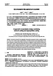
Fig. 1.
U1
Wireless multi-source cooperative communication network.
cocast (WNC) and space-time network coding (STNC) have been proposed by leveraging the idea of network coding in [14] and [15]. WNC in [14] can provide incremental diversity, while the STNC scheme in [15], which combines symbols in code division multiple access (CDMA) or frequency division multiple access (FDMA) mode at each relay, can solve the imperfect synchronization issue and achieve full diversity. 2𝑁 time slots are required by the STNC in [15] for a network of 𝑁 nodes to transmit 𝑁 packets. Compared to 𝑁 2 time slots for a traditional TDMA-based cooperative communication network of 𝑁 nodes [5], this is a substantial reduction in transmission delay. However, in both [14] and [15], extra frequency resource is required. All these asynchronous schemes have assumed CSI known at the receivers. However, as mentioned in previous part, channel estimation is challenging and often not possible in a fast-fading environment. To overcome the problem of channel estimation, differential encoding and modulation schemes for cooperative communications have been investigated, such as [16] and [17]. The differential scheme in [16] is based on space-time codes for MIMO systems, which would fail if the synchronization is imperfect. In [17], a single transmission with differential M-array phase shift keying (DMPSK) modulated symbols in TDMA manner can overcome the synchronization issue but causes large transmission delay. From the above discussion, there is a clear need of a cooperative communication scheme that can leverage the advantages of the discussed schemes while overcoming their shortages. In this paper, we first propose a differential space-time network coding (DSTNC) scheme for narrowband cooperative communication systems to solve the issues of imperfect synchronization and channel estimation. By exploiting the idea of STNC in [15], TDMA is also used in this paper. The differential encoding is performed across the symbols within the same packet at each node. Different from the STNC in [15], a combining function, which is determined by a network coding vector, is designed in this paper for each node to reduce the transmission delay while achieving full diversity. Note that due to the adoption of FDMA or CDMA in [15], more bandwidth is needed by the STNC scheme to separate different users’ signals. In our proposed DSTNC scheme, the same frequency band is used for the whole network and thus the proposed DSTNC scheme has higher spectral efficiency than the STNC in [15]. The network coding here, which
3147
is a set of complex parameters optimized for conventional signal constellations, is different from the traditional network coding, which linearly combines Galois symbols with coding coefficients picked from a finite field of fixed size [18], [19]. We analyze the pairwise error probability (PEP) performance of the proposed DSTNC scheme and derive the diversity criterion and product criterion for the design of the DSTNC. It is verified by the simulations that full diversity can be achieved by the proposed DSTNC scheme. For broadband cooperative communications, orthogonal frequency-division multiplexing (OFDM) is used at each user node. A distributed differential space-time-frequency network code (DSTFNC) is designed from the proposed DSTNC via mapping. The DSTFNC is differentially encoded over subcarriers within each OFDM block. Therefore, it can be decoded even the fading channels remain constant only within each OFDM block and may change independently from one OFDM block to another. When a statistical channel powerdelay profile (PDP) is known at the corresponding user node, a smooth logical channel similar to [20] is created independently at each user node to improve the performance of the DSTFNC scheme. Simulation results show that the proposed DSTFNC scheme provides the expected full diversity even in some high mobility scenarios, where the channel may change within one OFDM block due to Doppler effects. The rest of the paper is organized as follows. In Section II, system model and differential transmission for narrow-band cooperative communications are introduced. In Section III, the PEP performance is analyzed for frequency flat channels and the design of DSTNC is discussed. In Section IV, DSTFNC for broadband cooperative communications is generated from DSTNC and the permutation method for each node to create the smooth logical channel is illustrated when the corresponding PDP is known. In Section V, simulation results are shown to validate the proposed schemes. Finally, we draw our conclusions in Section VI. Notations: Upper (lower) case boldface letters stand for matrices (vectors). ⊗ is the Kronecker product. T and H denote transposition and conjugate transposition of a matrix, respectively. E stands for expectation. ∥A∥F denotes the Frobenius norm of matrix A. I𝑁 is an 𝑁 × 𝑁 unit matrix. 0𝑁 and 1𝑁 are 𝑁 × 1 all-zero vector and all-one vector, respectively. diag[𝑑1 , . . . , 𝑑𝑁 ] is the 𝑁 × 𝑁 diagonal matrix whose 𝑖th diagonal entry is 𝑑𝑖 . II. S YSTEM M ODEL Consider a wireless multi-source cooperative communication network depicted in Fig. 1, in which a set of 𝑁 user nodes 𝑈𝑖 , 1 ≤ 𝑖 ≤ 𝑁 , each equipped with a single antenna, cooperate to transmit their information to the destination node 𝐷. Without loss of generality, the transmitted information can be represented in terms of symbols. Nevertheless, the nodes will transmit packets that contains a large number of symbols. The destination will collect all the transmitted packets and then jointly detect the transmitted information as in the traditional network coding [18], [19]. Selective decode-and-forward protocol [1] is adopted in the cooperative communication network. For mathematical tractability, we
3148
IEEE TRANSACTIONS ON COMMUNICATIONS, VOL. 59, NO. 11, NOVEMBER 2011
Phase I
T1
• • •
1 tx s1
• • •
Phase II
TN N tx sN
• • •
T2 N −1
• • •
TN ( N −1) + 2
• • •
2 tx s1
• • •
N tx s1
• • •
1 tx s N
• • • N-1 tx sN time
(a)
T1 1 tx s1
• • • • • •
TN N tx s N
TN +1
• • •
1 tx x1
• • •
(b)
T2 N −1 N-1 tx xN −1
space-time block with the k th symbols
TN 2
TN +1
T2 N N tx xN time
Fig. 2. Illustration of two-phase cooperative communications of repetitionbased successive transmissions (a) and network coding transmissions (b).
assume that the relays can judge whether the received symbols are decoded correctly or not [5]. It is shown in [5] that this assumption is very close to the performance of practical scenario of comparing the received SNR to a threshold, especially when the nodes operate in high SNR, for example, when the nodes are close to each other. The channels between any two nodes in the network are modeled as narrow-band Rayleigh fading with additive white Gaussian noise (AWGN). Let 𝑔𝑚𝑛 and ℎ𝑚 denote the channel between 𝑈𝑚 and 𝑈𝑛 and the channel between 𝑈𝑚 and 𝐷, ∀𝑚, 𝑛 ∈ [1, 𝑁 ], respectively. Then 𝑔𝑚𝑛 and ℎ𝑚 are modeled as independent zero-mean, complex 2 Gaussian random variables with variances E∣𝑔𝑚𝑛 ∣2 = 𝜎𝑚𝑛 2 2 and E∣ℎ𝑚 ∣ = 𝜎𝑚 , respectively. The channel variances are 2 2 −𝜈 = 𝜅𝑑−𝜈 𝜎𝑚𝑛 𝑚𝑛 and 𝜎𝑚 = 𝜅𝑑𝑚 , where 𝜅 is a constant whose value depends on the propagation environment, 𝑑𝑚𝑛 and 𝑑𝑚 is the distance between 𝑈𝑚 and 𝑈𝑛 and the distance between 𝑈𝑚 and 𝐷, respectively, and 𝜈 is the path loss exponent, whose value is usually in the range between 2 and 4. A. Transmission Model Fig. 2 illustrates the transmission procedure for a twophase cooperative communication. Each transmission period comprises two phases, the broadcasting phase (Phase I) and the encoding/relaying phase (Phase II). Assume that TDMA is used in each phase and frame synchronization has been established. In each phase, each node is assigned a time slot to transmit its packet, which contains a large number of symbols. The source nodes take turns to exchange their information in Phase I. In Phase II, unlike the traditional cooperative communication, where the nodes repeat the received packets, each node transmits a new packet, whose symbols are generated by combing the received symbols from different nodes with its network coding vector. Fig. 3 illustrates the differential space-time network code with the 𝑘th symbols of the 𝑁 packets in one transmission period. In Phase I, each user node 𝑈𝑚 , 𝑚 ∈ [1, 𝑁 ], is assigned a time slot 𝑇𝑚 to broadcast its packet to the rest of the user nodes with power 𝑃𝐼 , where the 𝑘th transmitted symbol is 𝑘 𝑣𝑚 . In Phase II, each node transmits a new packet with power 𝑃𝐼𝐼 , and the 𝑘th transmitted symbols of the packets are 𝑥𝑘𝑛 , 𝑛 ∈ [1, 𝑁 ]. Let 𝑃𝑡 = 𝑃𝐼 + 𝑃𝐼𝐼 be the total transmit power for a transmission. Assume that user nodes are far away from 𝐷, and the distance among the user nodes is small compared to the distance between the user nodes and 𝐷. A small 𝑃𝐼 is enough for the transmission in Phase I. Thus there is no direct link between the use nodes and the destination node in Phase I.
Fig. 3. The construction of the DSTNC with the 𝑘th transmitted symbols of the 𝑁 packets for narrowband cooperative communications.
1) Signal Transmission in Phase I: Denote the 𝑘th information symbols of the 𝑁 packets as a vector s𝑘 = [𝑠𝑘1 , 𝑠𝑘2 , ..., 𝑠𝑘𝑁 ]T with 𝑘 ∈ [0, 𝑁𝑠 − 1], where 𝑁𝑠 is the number of information symbols in a packet. The information symbol 𝑠𝑘𝑚 of 𝑈𝑚 , 𝑚 ∈ [1, 𝑁 ], is from an M-QAM constellation 𝒜. Since no CSI is available at the user nodes, the trans𝑘 mitted symbol 𝑣𝑚 in Phase I is differentially encoded as 𝑘−1 𝑣 𝑘 = 𝑠𝑘𝑚 ∣𝑣𝑚 with 𝑘 = 0 denoting the initial reference 𝑣𝑚 𝑘−1 𝑚 ∣ symbol. The 𝑘th transmitted symbol of 𝑈𝑚 received at 𝑈𝑛 in Phase I can be written as √ 𝑘 𝑘 𝑘 𝑘 = 𝑃𝐼 𝑔𝑚𝑛 𝑣𝑚 + 𝑤𝑚𝑛 , (1) 𝑦𝑚𝑛 𝑘 𝑘 where 𝑤𝑚𝑛 is zero-mean and 𝑁0 -variance AWGN, 𝑔𝑚𝑛 is the channel between 𝑈𝑚 and 𝑈𝑛 during the transmission of 𝑘 𝑣𝑚 . After decoding, 𝑈𝑛 obtains a set of estimated symbols 𝑘 ˆs𝑛 = [ˆ 𝑠𝑘1𝑛 , ...., 𝑠ˆ𝑘𝑚𝑛 , ..., 𝑠ˆ𝑘𝑁 𝑛 ]T from other nodes, where 𝑠ˆ𝑘𝑚𝑛 = 𝑘 𝛽𝑚𝑛 𝑠𝑚 with 𝛽𝑚𝑛 indicating the detection state at 𝑈𝑛 for 𝑠𝑘𝑚 . 𝛽𝑚𝑛 for 𝑚 ∕= 𝑛 can be formulated as { 1, 𝑠ˆ𝑘𝑚𝑛 = 𝑠𝑘𝑚 𝛽𝑚𝑛 = . (2) 0, 𝑠ˆ𝑘𝑚𝑛 ∕= 𝑠𝑘𝑚
It is obvious that 𝛽𝑛𝑛 = 1 due to the fact that 𝑈𝑛 always has its own information. The detection states demonstrate that the user nodes just relay the symbols decoded correctly. Then 𝑈𝑛 combines the elements of the estimation ˆs𝑘𝑛 using a linear function to form a unique symbol as follows 𝑁 ∑ (3) 𝑎𝑚𝑛 𝑠ˆ𝑘𝑚𝑛 = aT𝑛 ˆs𝑘𝑛 𝑢𝑘𝑛 = 𝑓𝑛 (ˆs𝑘𝑛 ) = 𝑚=1
with a𝑛 = [𝑎1𝑛 , ..., 𝑎𝑛𝑛 , ..., 𝑎𝑁 𝑛 ]T . Assume that aT𝑛 a𝑛 = 1. We call the combining factors 𝑎𝑚𝑛 , 𝑚, 𝑛 ∈ [1, 𝑁 ], as network coding coefficients and a𝑛 as the network coding vector at 𝑈𝑛 . 2) Signal Transmission in Phase II: Because the destination does not have CSI, each user node would transmit the combined symbol 𝑢𝑘𝑛 differentially in Phase II, where 𝑛 ∈ [1, 𝑁 ], 𝑘 ∈ [0, 𝑁𝑠 − 1]. The nodes transmit their packets in their assigned time slots, and the 𝑘th transmitted symbols
GAO et al.: DIFFERENTIAL SPACE-TIME NETWORK CODING FOR MULTI-SOURCE COOPERATIVE COMMUNICATIONS
of the 𝑁 packets can be written as a diagonal space-time matrix D𝑘𝑥 = diag[𝑥𝑘1 , . . . , 𝑥𝑘𝑛 , . . . , 𝑥𝑘𝑁 ], which is generated as follows ¯ 𝑘−1 , D𝑘 = D𝑘 D𝑘−1 D (4) 𝑥
𝑢
𝑥
𝑥
𝑘−1 diag[𝑥𝑘−1 , . . . , 𝑥𝑘−1 𝑛 , . . . , 𝑥𝑁 ] 1
D𝑘−1 𝑥
= represents where the space-time block with the (𝑘 − 1)th transmitted symbols of the 𝑁 packets, D𝑘𝑢 = diag[𝑢𝑘1 , . . . , 𝑢𝑘𝑛 , . . . , 𝑢𝑘𝑁 ] is the information block with the 𝑘th combined symbols of the 𝑁 1 1 1 ¯ 𝑘−1 users, and D = diag[ ∣𝑥𝑘−1 , . . . , ∣𝑥𝑘−1 , . . . , ∣𝑥𝑘−1 ] is the 𝑥 ∣ ∣ ∣ 𝑛 1 𝑁 normalization block. Thus the 𝑘th transmitted symbol of 𝑈𝑛 ’s 𝑥𝑘−1 𝑛 packet in Phase II is 𝑥𝑘𝑛 = 𝑢𝑘𝑛 ∣𝑥𝑘−1 , which is differentially ∣ 𝑛
encoded between the combined symbol 𝑢𝑘𝑛 and the (𝑘 − 1)th ¯ 𝑘−1 prevents symbol of the packet. The normalization block D 𝑥 the peak power of the transmitted signals from being too large or too small. At the end of Phase II, 𝐷 has received the 𝑁 packets from the 𝑁 user nodes. The 𝑘th signals of the received packets at 𝐷 can be written as √ (5) y𝑘 = 𝑃𝐼𝐼 D𝑘𝑥 h𝑘 + w𝑘 , 𝑘 T = [𝑦1𝑘 , . . . , 𝑦𝑛𝑘 , . . . , 𝑦𝑁 ] , w𝑘 = where y𝑘 𝑘 𝑘 𝑘 T [𝑤1 , . . . , 𝑤𝑛 , . . . , 𝑤𝑁 ] ∼ 𝒞𝒩 (0, I𝑁 𝑁0 ) is the received noise vector, h𝑘 = [ℎ𝑘1 , . . . , ℎ𝑘𝑛 , . . . , ℎ𝑘𝑁 ]T with ℎ𝑘𝑛 being the channel between 𝑈𝑛 and 𝐷 during the transmission of 𝑥𝑘𝑛 . Assume that the channels do not change significantly over a period of two adjacent symbols within one packet, i.e. 𝑘 𝑘−1 = ℎ𝑛 and 𝑔𝑚𝑛 = 𝑔𝑚𝑛 = 𝑔𝑚𝑛 . Thus we have ℎ𝑘𝑛 = ℎ𝑘−1 𝑛 𝑘 𝑘−1 h =h = h, and the received signals can be expressed as ¯ 𝑘−1 + w ˜ 𝑘, y𝑘 = D𝑘 y (6)
3149
As for the detection at 𝑈𝑛 in Phase I, with the assumption that the channels do not change significantly over a period of two adjacent symbols, the received signal at 𝑈𝑛 from 𝑈𝑚 in Phase I becomes √ 𝑘 𝑘 𝑘 𝑦𝑚𝑛 = 𝑃𝐼 𝑔𝑚𝑛 𝑣𝑚 + 𝑤𝑚𝑛 , (10) and the ML detection for 𝑠𝑘𝑚 at 𝑈𝑛 is 𝑘−1 2 ∣𝑦 𝑘 − 𝑠𝑚 𝑦𝑚𝑛 ∣ 𝑠ˆ𝑘𝑚𝑛 = arg min 𝑚𝑛 , 𝑠𝑚 ∈𝒜 𝜉𝑚 𝑁0
(11)
∣𝑠𝑘 ∣2
𝑚 where 𝜉𝑚 = 1 + ∣𝑣𝑘−1 . 2 𝑚 ∣ Note that in differential detection, because the receiver does not know the transmitted symbol, we can replace the signal terms in the variances of the equivalent noises with 2 2 𝐸[∣𝑢𝑘 𝐸[∣𝑠𝑘 𝑛∣ ] 𝑚∣ ] , and 𝜉 = 1 + their means, i.e. 𝜀𝑛 = 1 + ∣𝑥𝑘−1 𝑚 𝑘−1 2 . 2 ∣ ∣𝑣𝑚 ∣ 𝑛 Simulation results in Section V show that this approximation leads to very small performance degradation. Also note that the detection states of the user nodes are not available at 𝐷, therefore in the ML detector (9), 𝐷 assumes the user nodes can successfully decode. It is shown later by the simulations that the performances with and without knowledge of the detection states at 𝐷 are the same.
III. P ERFORMANCE A NALYSIS AND D ESIGN OF DSTNC In this section, the performance of the DSTNC scheme is analyzed, and the PEP is derived. Based on the PEP analysis, we derive two design criteria for the network coding vectors, i.e., the diversity criterion and the product criterion.
𝑢
¯ 𝑘−1 y𝑘−1 D 𝑥
¯ 𝑘−1 w𝑘−1 . ˜ 𝑘 = w𝑘 − D𝑘𝑢 D = and w where y 𝑥 𝑘 ˜ is zero-mean with the covariThe equivalent noise vector w ance matrix of ¯ 𝑘−1
A. PEP Analysis
To make the relationship clear, substitute (2) and (3) into the received signals in (6) to get
The accurate performance analysis of a differential coded system requires the consideration of the quadratic receiving structure [23] [24]. We can well approximate the performance in high SNR situations by using an equivalent coherent receiver model (8) with y ¯𝑘−1 acting as a known channel 𝑘 vector and w ˜ as the equivalent noise vector [25]. Since Σ𝑤 , the covariance matrix of w ˜ 𝑘 , is clearly a diagonal matrix, the equivalent noise remains uncorrelated but with unequal −1 variance entries. After normalized by Σ𝑤 2 , which can be estimated at 𝐷, (8) becomes
where S = diag[s , . . . , s ], A = diag[a1 , . . . , a𝑁 ], and B = diag[𝛽11 , . . . , 𝛽𝑁 1 , . . . , 𝛽1𝑁 , . . . , 𝛽𝑁 𝑁 ]. Based on the received signal vector in (8), the maximum likelihood (ML) detection is used at 𝐷, and the estimation of s𝑘 , can be written as s𝑘 , denoted as ˜ 𝑘 ˜ s𝑘 = arg min {[y𝑘 − SA¯ y𝑘−1 ]H Σ−1 y𝑘−1 ]}. (9) 𝑤 [y − SA¯ s𝑘 ∈𝒜𝑁
As shown in (9), the decoding complexity of ML detection increases exponentially with the number of user nodes. Thus for large 𝑁 and/or large constellation size, sphere decoding method [21] [22] can be used to reduce the complexity. For high density nodes, they can be divided into subgroups and each group uses a DSTNC of smaller size to reduce the decoding complexity while sacrificing some diversity.
−1
−1
(12)
− 12
˜ 𝑘 has a covariance matrix 𝑁0 I𝑁 . The ¯ 𝑘 = Σ𝑤 w where w normalization just adjusts the signal strength at 𝐷 so that the noise power is uniform, and it does not affect the codeword error probability. From the above equation, we can derive the PEP, i.e. the probability of transmitting s𝑘 and deciding in favor of another c𝑘 = [𝑐𝑘1 , 𝑐𝑘2 , ..., 𝑐𝑘𝑁 ]T at the detector, conditioned by previously received signals and the detection states at the user nodes. The PEP is given by y𝑘−1 , {𝛽11 , . . . , 𝛽𝑁 1 , . . . , 𝛽1𝑁 , . . . , 𝛽𝑁 𝑁 }) 𝑃 (s𝑘 → c𝑘 ∣¯ √ ( 𝑑2 (S, C) ) ( 𝑑2 (S, C) ) ≤ exp − , =𝑄 2𝑁0 4𝑁0 (13)
3150
IEEE TRANSACTIONS ON COMMUNICATIONS, VOL. 59, NO. 11, NOVEMBER 2011
where the inequality is the Chernoff bound [26], and 𝑑2 (S, C) is the distance between the received signals corresponding to respective codeword s𝑘 and c𝑘 . The distance can be written as ( )H ( ) y𝑘−1 Λ−1 ΔSBA¯ y𝑘−1 , (14) 𝑑2 (S, C) = ΔSBA¯ 𝑤 T
T
where ΔS = S−C with C = diag[c𝑘 , ..., c𝑘 ]. For moderate or high SNR √ scenarios, we make the following approximation h, and the distance becomes y𝑘−1 = 𝑃𝐼𝐼 D𝑘−1 𝑥 ( ) ( ) 1 ¯ 𝑥𝑘−1 D𝑥𝑘−1 HΛ− ¯ 𝑘−1 D𝑥𝑘−1 h. 𝑑2(S, C)= 𝑃𝐼𝐼 hH ΔSBAD 𝑤 ΔSBAD𝑥 (15)
Assuming that channels from different nodes to 𝐷 are spatially uncorrelated, averaging the bound in (13) with respect to h results in [26] 𝑃 (s𝑘 → c𝑘 ∣{𝛽11 , . . . , 𝛽𝑁 1 , . . . , 𝛽1𝑁 , . . . , 𝛽𝑁 𝑁 }) 𝑁 ( [ ( 𝑑2 (S, C) )] ∏ 𝑃𝐼𝐼 𝜆𝑛 )−1 = 1+ ≤ Eh exp − , 4𝑁0 4𝑁0 𝑛=1
𝑁 ( [∏ 𝑃𝐼𝐼 𝜆𝑛 )−1 ] 1+ . 4𝑁0 𝑛=1
(16)
𝑃 (s𝑘 → c𝑘 ) ≤
[(
E𝛽𝑚𝑛
𝑛=1
1+
∑ 𝑃𝐼𝐼 𝜎𝑛2 ∣ 𝑁 𝑚=1
(18)
𝛽𝑚𝑛 𝑎𝑚𝑛 Δ𝑠𝑚 ∣2 )−1 ]
4𝑁0 𝜀𝑚
∀𝑛 ∈ [1, 𝑁 ], ∀s𝑘 , c𝑘 ∈ 𝒜𝑁 .
(23)
Theorem 1: Let 𝑑𝑚𝑎𝑥 represent the maximum Euclidean distance of 𝒜. If ∀𝑛 ∈ [1, 𝑁 ], ∣aT𝑛 Δs∣ ∕= 0 holds true for any distinct pair {s𝑘 , c𝑘 }, the PEP under high SNR is upper bounded by ( 𝑃 )−𝑁 𝑡 𝑃 (s𝑘 → c𝑘 ) < 𝐺 (24) 𝑁0
𝐺=
𝑁 ( 4𝜀 ∑ 1 𝑛 + ∣aT𝑛 Δs∣2 (1 − 𝛼)𝜎𝑛2 𝑛=1 𝑁 ∏
𝑙=1,𝑙∕=𝑛
Because the signal detection at each user is independent and the detection of symbols from different sources at a certain user is also independent, the order of expectation operator and production operator in (18) can be exchanged as follows 𝑁 ∏
∣aT𝑛 Δs∣ ∕= 0,
where 𝐺 is coding advantage and
where 𝜆𝑛 is the eigenvalue of the following 𝑁 × 𝑁 diagonal matrix ( )H ( ) 1 1 ¯ 𝑘−1 D𝑘−1 Λ−1 ΔSBAD ¯ 𝑘−1 D𝑘−1 R 2 Rℎ2 ΔSBAD 𝑥 𝑥 𝑤 𝑥 𝑥 ℎ (17) 2 with Rℎ = diag[𝜎12 , . . . , 𝜎𝑁 ] being the correlation matrix of h. It is easy to verify that the 𝑛th eigenvalue is 𝜆𝑛 = 2 ∑ 𝜎𝑛 𝑁 2 𝑘 𝑘 𝑚=1 𝛽𝑚𝑛 𝑎𝑚𝑛 Δ𝑠𝑚 ∣ with Δ𝑠𝑚 = 𝑠𝑚 − 𝑐𝑚 . 𝜀𝑛 ∣ Averaging with respect to the detection states of the user nodes, the PEP can be written as 𝑃 (s𝑘 → c𝑘 ) ≤ E𝛽𝑚𝑛
Diversity is an important criterion since it determines the slop of the performance curve. However, it is obvious from (22) that ∣aT𝑛 Δs∣ = 0 would result in the loss of diversity. In order to achieve the maximum diversity, the first criterion of the network coding vectors is derived as follows. Diversity criterion: The full diversity gain 𝑁 can be achieved if the following maximum diversity condition holds true for any distinct pair {s𝑘 , c𝑘 },
.
(19)
Assuming that the SER at 𝑈𝑛 for the symbols from 𝑈𝑚 is 𝑝𝑚𝑛 , 𝛽𝑚𝑛 ’s are independent Bernoulli random variables with { a distribution 1 − 𝑝𝑚𝑛 , for 𝛽𝑚𝑛 = 1 (20) 𝑃 (𝛽𝑚𝑛 ) = 𝑝𝑚𝑛 , for 𝛽𝑚𝑛 = 0. Considering all possibilities of the detection state {𝛽11 , . . . , 𝛽𝑁 1 , . . . , 𝛽1𝑁 , . . . , 𝛽𝑁 𝑁 }, the PEP can be written as (21) which is shown on the top of this page. The first term in (21) represents the case when all symbols received at 𝑈𝑛 are decoded correctly, the second term represents the case when one of the symbols received at 𝑈𝑛 is decoded incorrectly, and so on. When SNR is high, SERs are small and the higher order terms of SERs could be ignored. Thus the PEP can be approximated by (22) on the top of this page, where H.O.T. stands for the higher order terms.
𝑁 𝐶𝑀 𝜉𝑙 𝑑2𝑚𝑎𝑥 ) 2 𝛼𝜎𝑙𝑛
𝑃𝐼 𝑃𝑡
with 𝛼 = . 𝐶𝑀 is constant for a certain constellation. Proof: See Appendix. It can be seen from (24) that, for a fixed number of user nodes, the adopted signal constellation, the power allocation 𝛼 and channel conditions can influence the coding advantage 𝐺 but not the diversity order. When given the constellation, 𝛼 and channel conditions, the PEP depends on the design of network coding vectors. Thus according to Theorem 1, the second design criterion is derived as follows to get a better performance. Product criterion: The minimum value of the product ∏𝑁 T 2 𝑘 𝑛=1 ∣a𝑛 Δs∣ over all pairs of distinct signal vectors s and 𝑘 c should be as large as possible. The product criterion is of secondary importance and should be optimized if full diversity is achieved. B. Design of DSTNC Let A𝑁 denote the combining matrix (network coding matrix), which is constructed from the network coding vectors of the 𝑁 user nodes as follows (25) AT𝑁 = [a1 ⋅ ⋅ ⋅ a𝑛 ⋅ ⋅ ⋅ a𝑁 ]. Let s𝑓 = A𝑁 s, where s = [𝑠1 , . . . , 𝑠𝑁 ]T ∈ 𝒜𝑁 . According to the diversity criterion, A𝑁 should be designed to satisfy the following property: the original signal constellation is rotated and expanded such that there is no zero entry in the vector s𝑓 for any s ∕= 0𝑁 . This is referred to as the signal space diversity technique [27] [28]. According to the product criterion, the minimum product distance of a set of signal points should be maximized, which is also investigated in [27], [28]. This diversity technique has been applied to MIMO coding schemes such as [29], [30]. Note that the combining matrices can be constructed based on Hadamard matrices and Vandermonde matrices. However, the combing matrices based on Vandermonde matrices result in larger minimum product distance than those based on Hadamard matrices [30]. A combining matrix based on Vandermonde matrices with parameters 𝜃1 , 𝜃2 , . . . , 𝜃𝑁 can be written as
GAO et al.: DIFFERENTIAL SPACE-TIME NETWORK CODING FOR MULTI-SOURCE COOPERATIVE COMMUNICATIONS
𝑁 [ ∏
𝑃 (s𝑘 → c𝑘 ) ≤
1+
𝑛=1
+
𝑁 ( ∑
𝑃 (s𝑘 → c𝑘 ) ≤ ≤
𝑁 [ ∏
1+
•
2 𝑃𝐼𝐼 𝜎𝑛 T 2 4𝑁0 𝜀𝑛 ∣a𝑛 Δs∣
2 𝑃𝐼𝐼 𝜎𝑛 T 2 4𝑁0 𝜀𝑛 ∣a𝑛 Δs∣
x1 (0)
repeat Γ times
• • •
v1 (0)
x1 (0)
v1 ( P − 1)
x1 ( P − 1)
• • •
𝑁 ∑
(1 −
(1 − 𝑝𝑖𝑛 )𝑝𝑙𝑛 + ⋅ ⋅ ⋅ +
𝑖=1,𝑖∕=𝑙,𝑖∕=𝑛
𝑝𝑚𝑛 ) +
𝑙=1,𝑙∕=𝑛
𝑁 ∑
𝑁 ∑
(1 −
𝑝𝑚𝑛 ) +
𝑚=1,𝑚∕=𝑛
repeat Γ times
time
repeat Γ times
• • •
v1 ( P − 1)
x1 ( P − 1) 0 N c − PΓ
•
•
• • vN (0)
•
• • •
•
• xN (0)
repeat Γ times
• • •
vN (0)
xN (0)
vN ( P − 1)
xN ( P − 1)
• • •
repeat Γ times
• • •
• • •
UN
repeat Γ times
• • •
repeat Γ times
xN ( P − 1)
vN ( P − 1)
0 N c − PΓ
0 N c − PΓ
Phase I
Phase II
Fig. 4. The construction of DSTFNC for broadband cooperative communications.
⎡ 1 AT𝑁 (𝜃1 , 𝜃2 , . . . , 𝜃𝑁 ) = √ 𝑁
1 𝜃1 .. .
⎢ ⎢ ⎢ ⎣ 𝜃1𝑁 −1
1 𝜃2 .. .
𝜃2𝑁 −1
⋅⋅⋅ ⋅⋅⋅ .. . ⋅⋅⋅
1 𝜃𝑁 .. .
𝑁 ∏
1 1+
2 𝑃𝐼𝐼 𝜎𝑛 2 4𝑁0 𝜀𝑛 ∣𝑎𝑛𝑛 Δ𝑠𝑛 ∣ 𝑚=1,𝑚∕=𝑛
1
1+
∑𝑁 2 𝑃𝐼𝐼 𝜎𝑛 𝑚=1,𝑚∕=𝑙 4𝑁0 𝜀𝑛 ∣
𝑎𝑚𝑛 Δ𝑠𝑚 ∣2
] 𝑝𝑙𝑛 + H.O.T. ,
] 𝑝𝑚𝑛 ,
(21)
] 𝑝𝑙𝑛 + H.O.T. (22)
𝑙=1,𝑙∕=𝑛
• • •
• • •
𝑁 ∑
𝑚=1,𝑚∕=𝑛
repeat Γ times
• • •
0 N c − PΓ
•
𝑎𝑚𝑛 Δ𝑠𝑚 ∣2
1 1+
)
𝑁 ∏
1
𝑁 [ ∏ 𝑛=1
U1
T 2 4𝑁0 𝜀𝑛 ∣a𝑛 Δs∣ 𝑚=1,𝑚∕=𝑛
∑𝑁 2 𝑃𝐼𝐼 𝜎𝑛 𝑚=1,𝑚∕=𝑙 4𝑁0 𝜀𝑛 ∣
𝑛=1
v1 (0)
(1 − 𝑝𝑚𝑛 )
2 𝑃𝐼𝐼 𝜎𝑛
1
1+
𝑙=1,𝑙∕=𝑛
𝑁 ∏
1
3151
⎤ ⎥ ⎥ ⎥. ⎦
𝑁 −1 𝜃𝑁 (26)
Some best known transform matrices AT𝑁 based on Vandermonde matrices are summarized in [30]. More constructions and details of the transform matrices can be found in [27], [28]. Based on the above description, the network coding vector 1 for 𝑈𝑛 is (27) a𝑛 = √ [1 𝜃𝑛 ⋅ ⋅ ⋅ 𝜃𝑛𝑁 −1 ]T , 𝑁 where 𝜃𝑛 is determined by the number of nodes and the construction method. This means each node can independently generate its combining function according to the assigned parameter 𝜃𝑛 , 𝑛 ∈ [1, 𝑁 ]. With these network coding vectors, the proposed DSTNC scheme can achieve full diversity, which equals the number of user nodes, without the requirement of synchronization or channel estimation. IV. D ESIGN OF DSTFNC F ROM DSTNC In this section we consider the differential transmission for broadband multi-source cooperative communications. The
channels in the network shown in Fig. 2 are assumed frequency selective fading. Assume that the numbers of multipaths between any pair of user nodes and between the user nodes and 𝐷 are 𝐿1 and 𝐿2 , respectively. The channel frequency response from 𝑈𝑚 to 𝑈𝑛 is given by 𝐺𝑚𝑛 (𝑞) = ∑𝐿1 −1 𝑚𝑛 (𝑙) −𝑗 2𝜋𝑞𝜏𝑇 , where 𝑞 ∈ [0, 𝑁𝑐 −1], 𝑔𝑚𝑛 (𝑙) and 𝑙=0 𝑔𝑚𝑛 (𝑙)𝑒 𝜏𝑚𝑛 (𝑙) are the complex amplitude and delay of the 𝑙th path, respectively, and 𝑇 is the OFDM symbol period. The channel coefficients 𝑔𝑚𝑛 (𝑙)’s are modeled as zero-mean complex 2 Gaussian variables with variances E∣𝑔𝑚𝑛 (𝑙)∣2 = 𝜎𝑚𝑛,𝑙 . 𝑔𝑚𝑛 (𝑙) − 1] are assumed for different 𝑚, 𝑛 ∈ [1, 𝑁 ] and 𝑙 ∈ [0, 𝐿 1 ∑𝐿1 −1 2 2 independent, and the total power is 𝑙=0 𝜎𝑚𝑛,𝑙 = 𝜎𝑚𝑛 . The channel frequency response from 𝑈𝑚 to 𝐷 is given ∑𝐿2 −1 −𝑗 2𝜋𝑞𝜏𝑇𝑚 (𝑙) , where ℎ𝑚 (𝑙) and by 𝐻𝑚 (𝑞) = 𝑙=0 ℎ𝑚 (𝑙)𝑒 𝜏𝑚 (𝑙) are the complex amplitude and delay of the 𝑙th path, respectively. The channel coefficients ℎ𝑚 (𝑙)’s are modeled as zero-mean complex Gaussian variables with variances E∣ℎ𝑚 (𝑙)∣2 = 𝜎𝑚,𝑙 and ℎ𝑚 (𝑙) for different 𝑚 ∈ [1, 𝑁 ] and 𝑙 ∈ [0, 𝐿2 − 1] are assumed The total power is ∑𝐿2 −1 independent. 2 2 𝜎𝑚,𝑙 = 𝜎𝑚 . TDMA is still used normalized such that 𝑙=0 in Phase I and Phase II to overcome the imperfect synchronization issue. Each user node employs an OFDM modulator with 𝑁𝑐 subcarriers. Based on the proposed DSTNC scheme, a differential encoding scheme in frequency domain within each OFDM block is designed. A. Distributed DSTFNC From DSTNC The distributed DSTFNC scheme is motivated by the differential space-frequency modulation scheme in [20]. Full diversity space frequency codes for MIMO-OFDM systems are obtained from space time codes via mapping in [31]. In this subsection, we will generate the DSTFNC for broadband multi-source cooperative communication systems by mapping from the proposed DSTNC. The two phases of a transmission is illustrated in Fig. 4, which has a similar structure to Fig. 3. The OFDM block for each user is divided into 𝑃 groups in which each transmitted symbol is repeated Γ times, where 1 ≤ Γ ≤ 𝐿2 and 𝑃 = ⌊ 𝑁Γ𝑐 ⌋, i.e., the largest integer not greater than 𝑁Γ𝑐 . The integer Γ is adjustable for different diversities. 𝑝 = 0 is the reference group for the differential coding. 1) Differential Transmission in Phase I: The 𝑝th group in the 𝑚th OFDM period received at 𝑈𝑛 in Phase I can be written
3152
as
IEEE TRANSACTIONS ON COMMUNICATIONS, VOL. 59, NO. 11, NOVEMBER 2011
𝑝 y𝑚𝑛
√ 𝑝 = 𝑃𝐼 1Γ ⊗ 𝑣𝑚 (𝑝)G𝑝𝑚𝑛 + w𝑚𝑛 ,
𝑝 y𝑚𝑛
T
(𝑚)
(28)
= [𝑦𝑚𝑛 (𝑘𝑝,1 ), ..., 𝑦𝑚𝑛 (𝑘𝑝,Γ )] with 𝑦𝑚𝑛 (𝑘𝑝,𝑙 ) where being the signal received from 𝑈𝑚 on the 𝑘𝑝,𝑙 th sub𝑝 carrier, and w𝑚𝑛 = [𝑤𝑚𝑛 (𝑘𝑝,1 ), ..., 𝑤𝑚𝑛 (𝑘𝑝,Γ )]T with 𝑤𝑚𝑛 (𝑘𝑝,𝛾 ) being the zero-mean and 𝑁0 -variance AWGN on the 𝑘𝑝𝑙 th subcarrier received from 𝑈𝑚 at 𝑈𝑛 , and G𝑝𝑚𝑛 = [𝐺𝑚𝑛 (𝑘𝑝,1 ), ..., 𝐺𝑚𝑛 (𝑘𝑝,Γ )]T . As in Section II. A, the trans(𝑝−1) mitted symbol is 𝑣𝑚 (𝑝) = 𝑠𝑚 (𝑝) ∣𝑣𝑣𝑚 , where 𝑠𝑚 (𝑝) is 𝑚 (𝑝−1)∣ the 𝑝th information symbol of 𝑈𝑚 . Note that the processing is the same as that for frequency flat fading except that the differential modulation is performed over subcarriers. After decoding in Phase I, 𝑈𝑛 obtains a set of estimaˆ 𝑛 = [ˆs1𝑛 , ...., ˆs𝑚𝑛 , ..., ˆs𝑁 𝑛 ]T from other users, where tions S ˆs𝑚𝑛 = [ˆ 𝑠𝑚𝑛 (0), 𝑠ˆ𝑚𝑛 (1), ..., 𝑠ˆ𝑚𝑛 (𝑃 − 1)]T is the estimated signal vector from 𝑈𝑚 . According to (3), the combined symbol generated at 𝑈𝑛 for 𝑝 = 0, 1, ..𝑃 − 1 is
received by 𝐷 on the 𝑘𝑝,𝛾 th subcarrier during the 𝑚th OFDM period in Phase II. It can be seen from (30)-(32) that the signals are differentially encoded over groups of subcarriers. the channel difference Define Δℎ,𝑝 = H𝑝 − H𝑝−1 as √ between H𝑝 and H𝑝−1 . Since y𝑝 = 𝑃𝐼𝐼 D𝑋𝑝 H𝑝 + w𝑝 and ¯ 𝑝−1 )D𝑋 , we have D𝑋𝑝 = IΓ ⊗ (D𝑝𝑢 D 𝑝−1 𝑥 √ ¯ 𝑝−1 )y𝑝−1 + 𝑃𝐼𝐼 D𝑋𝑝 Δℎ,𝑝 + w y𝑝 = IΓ ⊗ (D𝑝𝑢 D ˜ 𝑝 (34) 𝑥 ¯ 𝑝−1 )w𝑝−1 . The equivalent noise where w ˜ 𝑝 = w𝑝 −IΓ ⊗(D𝑝𝑢 D 𝑥 𝑝 w ˜ is zero-mean and the variance is Σ′𝑤 = E[w ˜ 𝑝 (w ˜ 𝑝 )H ]
It is obvious that Λ′𝑤 = IΓ ⊗ Λ𝑤 , where Λ𝑤 is defined in (7). B. Decoding and Channel Permutation
1) Decoding at 𝐷 in Phase II: We consider differential decoding over two adjacent received groups y𝑝 and y𝑝−1 for (29) 𝑢𝑛 (𝑝) = 𝑓𝑛 (ˆs𝑛 (𝑝)) = 𝑎𝑚𝑛 𝑠ˆ𝑚𝑛 (𝑝) = any 𝑝 = 1, 2, ...𝑃 − 1, where 𝑝 = 0 is the reference group. 𝑚=1 Let s𝑝 = [𝑠1 (𝑝), 𝑠2 (𝑝), ..., 𝑠𝑁 (𝑝)]T denote the 𝑝th information 𝑠1𝑛 (𝑝), 𝑠ˆ2𝑛 (𝑝), ..., 𝑠ˆ𝑁 𝑛 (𝑝)]T and a𝑛 is the symbols from the 𝑁 user nodes and S = diag[sT , ..., sT ]. If where ˆs𝑛,𝑝 = [ˆ 𝑝 √𝑝 coding vector designed in Section III. H𝑝 ≈ H𝑝−1 , or ∥ Δℎ,𝑝 ∥𝐹 is small enough such that 𝑃𝐼𝐼 ∥ 2) Differential Transmission in Phase II: Because 𝐷 does Δℎ,𝑝 ∥𝐹 is much less than ∥ w ˜ 𝑝 ∥𝐹 [20], then a near ML not have any kind of CSI, the users transmit their 𝑝th combined decoding can be performed as (36) on the top of this page. symbols u𝑝 = [𝑢1 (𝑝), 𝑢2 (𝑝), ..., 𝑢𝑁 (𝑝)] differentially. Let X𝑝 When N and/or constellation size is large, sphere decoder [21] denote the 𝑝th group of the DSTFNC, which can be formulated [22] can be used to reduce the decoding complexity. as (30) X𝑝 = 1Γ ⊗ D𝑝𝑥 , 2) Channel Permutation at Each User Node in Phase II: When the delay spread is small with respect to the OFDM 𝑝 where D𝑥 = diag[𝑥1 (𝑝), 𝑥2 (𝑝), ..., 𝑥𝑁 (𝑝)] with 𝑥𝑛 (𝑝) being period, the channel frequency response changes slowly over the transmitted symbol in the 𝑝th group of the OFDM symbol two adjacent subcarriers. In this case, the subcarrier indices 𝑝 from 𝑈𝑛 . D𝑥 is differentially encoded according to (4), (𝑚) (𝑚) 𝑝 𝑝 𝑝−1 ¯ 𝑝−1 (31) 𝑘𝑝,𝛾 and 𝑘𝑝−1,𝛾 for 𝑈𝑚 , 𝑚 ∈ [1, 𝑁 ], can be chosen as the two D𝑥 = D𝑢 D𝑥 D𝑥 , adjacent subcarriers of H𝑚 = [𝐻𝑚 (0), 𝐻𝑚 (1), ..., 𝐻𝑚 (𝑁𝑐 − where D𝑝𝑢 = diag[𝑢1 (𝑝), 𝑢2 (𝑝), ..., 𝑢𝑁 (𝑝)], D𝑝−1 = 1)]. When the delay spread is large with respect to the OFDM 𝑥 ¯ 𝑝−1 = period, the channel frequency response changes rapidly. In this diag[𝑥1 (𝑝 − 1), 𝑥2 (𝑝 − 1), ..., 𝑥𝑁 (𝑝 − 1)], and D 𝑥 1 1 1 diag[ ∣𝑥1 (𝑝−1)∣ , ∣𝑥2 (𝑝−1)∣ , ..., ∣𝑥𝑁 (𝑝−1)∣ ]. Obviously, D𝑝𝑥 is the case, when the statistical channel PDP (not exact CSI) from DSTNC in Section II. The difference is that the DSTNC is 𝑈𝑛 to 𝐷 is known at 𝑈𝑛 , we can permute the subcarriers to differentially encoded in time domain while the DSTFNC is get smooth logical channels so that the differential decoding in frequency domain. Ignoring the zeros filled in Fig. 4(b) can be performed successfully. Because the permutation opwhen 𝑁𝑐 is not an integer multiple of 𝑁 Γ, the DSTFNC can timization by maximizing the SER or bit error rate (BER) is be written as a concatenation of the 𝑃 groups intractable, we consider an permutation approach of maximiz(32) ing the average SNR as in [20]. X = [XT0 , XT1 , ..., XT𝑃 −1 ]T . Define the average ( SNR as ) ∑𝑃 −1 Let D𝑋𝑝 = diag[𝑥1 (𝑝), . . . , 𝑥𝑁 (𝑝), . . . , 𝑥1 (𝑝), . . . , 𝑥𝑁 (𝑝)] 𝑝 ¯ 𝑝−1 𝑝−1 2 D E∥I ⊗ (D )y ∥ Γ 𝑢 𝑥 F 𝑝=1 denote the diagonal version of X𝑝 . Then the 𝑝th group of the ( √ ). (37) SNR𝑎𝑣 = ∑ 𝑃 −1 received signals at 𝐷 can be written as 𝑝 ∥2 E∥ 𝑃 D .Δ + w ˜ 𝐼𝐼 𝑋𝑝 ℎ,𝑝 F 𝑝=1 √ ) (33) y𝑝 = 𝑃𝐼𝐼 D𝑋𝑝 H𝑝 + w𝑝 , ∑𝑃 −1 ( √ E∥ 𝑃𝐼𝐼 D𝑋𝑝 Δℎ,𝑝 + w ˜ 𝑝 ∥2F to We try to minimize 𝑝=1 (1) (𝑁) (1) (𝑁) where H𝑝 = [𝐻1(𝑘𝑝,1 ), . . . ,𝐻𝑁(𝑘𝑝,1 ), . . . ,𝐻1(𝑘𝑝,Γ ), . . . ,𝐻𝑁(𝑘𝑝,Γ)]Tmaximize SNR𝑎𝑣 . Because the noise, the signals, and the is the 𝑝th group of channel vector with channels are independent with each other, we can simplify the (𝑚) 𝑘𝑝,𝛾 ∈ [0, 𝑁𝑐 − 1] being the index of subcarrier minimization(problem as (38) on the top of this page, where ) (𝑛) (𝑛) = Φ = ∑𝑃 −1 E∣𝑥 (𝑝)∣2 E ∑Γ ∣𝐻 (𝑘𝑝,𝛾 on which 𝑥𝑚 (𝑝) is transmitted by 𝑈𝑚 , y𝑝 ) − 𝐻𝑛 (𝑘𝑝−1,𝛾 )∣2 . 𝑛 𝑛 𝑛 𝑝=1 𝛾=1 (1) (𝑁 ) (1) (𝑁 ) T [𝑦1 (𝑘𝑝,1 ), . . . , 𝑦𝑁 (𝑘𝑝,1 ), . . . , 𝑦1 (𝑘𝑝,Γ ), . . . , 𝑦𝑁 (𝑘𝑝,Γ )] E∣𝑥𝑛 (𝑝)∣2 is a constant related to the signal constellation, so is the 𝑝th group of the received signal vector we will omit it in the following. It can be seen from (38) that (𝑚) with 𝑦𝑚 (𝑘𝑝,𝛾 ) being the signal received from the minimization problem can be solved by minimizing Φ 𝑛 (𝑚) = independently at each user node. Therefore, the permutation 𝑈𝑚 on the 𝑘𝑝,𝛾 th subcarrier, and w𝑝 (1) (𝑁 ) (1) (𝑁 ) [𝑤1 (𝑘𝑝,1 ), . . . , 𝑤𝑁 (𝑘𝑝,1 ), . . . , 𝑤1 (𝑘𝑝,Γ ), . . . , 𝑤𝑁 (𝑘𝑝,Γ )]T approach for a certain user node 𝑈𝑛 is considered and the (𝑚) with 𝑤𝑚 (𝑘𝑝,𝛾 ) being the zero-mean AWGN with variance 𝑁0 other nodes can permute their subcarriers in the same way. 𝑁 ∑
aT𝑛 ˆs𝑛,𝑝 ,
GAO et al.: DIFFERENTIAL SPACE-TIME NETWORK CODING FOR MULTI-SOURCE COOPERATIVE COMMUNICATIONS
For 𝑈𝑛 , Φ𝑛 can be written as (39), which is on the top ∑ 2 −1 2 𝜏𝑛 (𝑙)(𝑖−𝑗) 2 of this page. Let 𝑑(𝑖, 𝑗) = 𝐿 ]. Then 𝑙=0 4𝜎𝑛,𝑙 sin [ 𝑇 Φ𝑛 becomes
𝑝=1 𝛾=1
(𝑛)
(𝑛) 𝑑(𝑘𝑝,𝛾 , 𝑘𝑝−1,𝛾 ).
Γ 𝑝 ∑ ∣𝑦𝑚𝑛 (𝑘𝑝,𝛾 ) − 𝑠𝑚 𝑦𝑚𝑛,𝑝−1 (𝑘𝑝−1,𝛾 )∣2 , ′ 𝑁 𝑠𝑚 ∈𝒜 𝜉𝑚 0 𝛾=1 (41) 2 𝑚 (𝑝)∣ ′ where 𝜉𝑚 = 1 + ∣𝑣E∣𝑠 . To decode successfully for 2 𝑚 (𝑝−1)∣ different delay spreads, the sets of the subcarriers can be permutated through the same way described above.
𝑠ˆ𝑚𝑛 (𝑝) = arg min
V. S IMULATION R ESULTS In this section, we present simulation results of the DSTNC and the STFNC for narrow-band and broadband wireless multi-source cooperative communications, respectively. Various numbers of user nodes are used with 𝑁 = 2, 3, and 4. The corresponding network coding vectors are generated
𝑙=0 (𝑛) 𝑘𝑝−1,𝛾 )
(𝑛) 2𝜋𝑘 𝜏 (𝑙) 𝑝−1,𝛾 𝑛 𝑇
∣2 (39)
].
0
−1
10
(40)
The minimization of Φ𝑛 in (40) is the shortest-path problem [32] and can be solved by using the idea of Dijkstra’s algorithm [20], [32] as follows. ∙ Let 𝑉0 = {1, 2, ..., 𝑃 Γ}. Randomly choose Γ elements {𝑘0,1 , ..., 𝑘0,Γ } from 𝑉0 to form a set 𝐸0 , and let the rest elements be 𝑉1 = 𝑉0 − 𝐸0 . ∙ For p=1:P-1 1) Choose Γ elements {𝑘𝑝,1 , ..., 𝑘𝑝,Γ } from 𝑉𝑝 to form a set 𝐸𝑝 whose elements are nearest to the set 𝐸𝑝−1 , ∑Γ i.e., to minimize 𝛾=1 𝑑(𝑘𝑝,𝛾 , 𝑘𝑝−1,𝛾 ). 2) Denote the set of the rest elements as 𝑉𝑝+1 = 𝑉𝑝 − 𝐸𝑝 . By independently minimizing Φ𝑛 , 𝑛 ∈ [1, 𝑁 ], each user can get a smooth logical channel. 3) Decoding and Channel Permutation in Phase I: As for the signal detection in Phase I, differential decoding is performed. Define Δ𝑔,𝑝 = G𝑝𝑚𝑛 − G𝑝−1 𝑚𝑛 as the channel difference between G𝑝𝑚𝑛 and G𝑝−1 . Assuming that G𝑝𝑚𝑛 ≈ 𝑚𝑛 𝑝−1 G𝑚𝑛 , or ∥Δ𝑔,𝑝 ∥F is small enough, a near ML detection for 𝑠𝑚 (𝑝), 𝑝 ∈ [0, 𝑃 − 1], can be written as
ℎ𝑛 (𝑙)𝑒−𝑗
10
−2
10
BER
Φ𝑛 =
𝑃 −1 ∑ Γ ∑
𝐿∑ 2 −1
−3
10
−4
10
N=2, unknown detection states N=3, unknown detection states N=4, unknown detection states N=2, known detection states N=3, known detection states N=4, known detection states no cooperation N=2, QPSK
−5
10
−6
10
4
6
8
10
12
14 Pt/N0 dB
16
18
20
22
24
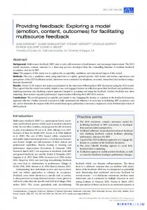
Fig. 5. BER performance of DSTNC for different number of user nodes with 𝑑𝑢 = 𝑑/3.
4𝑛−3
according to (27). For 𝑁 = 2, 𝜃𝑛 = 𝑒𝑗 4 𝜋 with 𝑛 = 1, 2, 2(𝑛−1) 1 for 𝑁 = 3, 𝜃𝑛 = 𝑒𝑗( 9 + 3 )𝜋 with 𝑛 = 1, 2, 3, and for 4𝑛−3 𝑁 = 4, 𝜃𝑛 = 𝑒𝑗 8 𝜋 with 𝑛 = 1, 2, 3, 4. In the simulations, the user nodes have the same distance from 𝐷, denoted by 𝑑, and the channel variance between the user nodes to 𝐷 is assumed to be 1. The inter-user distances are the same and denoted by 𝑑𝑢 with 𝑑𝑢 < 𝑑. The path loss exponent is 𝜈 = 3. The total transmit power of each user for one transmission is 𝑃𝑡 = 𝑃𝐼 + 𝑃𝐼𝐼 , and 𝑃𝐼 = 𝛼𝑃𝑡 . In this work, we do not derive the optimal value for 𝛼 because solving the optimization problem requires CSI of all the links known at each user node or a central controller. Such an optimization problem is out of the scope of this paper. However, the influence of 𝛼 on the performance of the proposed schemes is given in the simulations. For the narrow-band cooperative communications, the channel coefficients follow the Jakes’ model [33] with Doppler frequency 𝑓𝐷 and normalized fading parameter 𝑓𝐷 𝑇𝑠 , where 𝑇𝑠 is the sampling period which equals the symbol period. Unless specified otherwise, 𝑓𝑑 𝑇𝑠 = 0.0025 is used throughout the simulation.
3154
IEEE TRANSACTIONS ON COMMUNICATIONS, VOL. 59, NO. 11, NOVEMBER 2011
0
0
10
10 N=2, du=2d/3
f T =0.0025
N=2, d =d/2
fdTs=0.01
d s
u
N=2,d =d/3
f T =0.025
u
d s
−1
N=2, error free relaying N=2, error free, exact
−1
10
fdTs=0.05
10
−2
BER
BER
10 −2
10
−3
10
−3
10
−4
10
−4
10
−5
4
6
8
10
12 14 Pt/N0 dB
16
18
20
22
Fig. 6. BER performance of DSTNC for different distance between the user nodes with 𝑁 = 2.
0
10
α=0.01 α=0.1 α=0.3
−1
BER
10
−2
10
−3
10
−4
10
4
6
8
10
12 14 Pt/N0 dB
16
18
20
22
Fig. 7. The influence of different 𝛼 on BER performance of DSTNC with 𝑁 = 2.
Fig. 5 shows the BER performance versus SNR 𝑃𝑡 /𝑁0 of the DSTNC scheme with 𝑁 = 2, 3, 4 user nodes. In the simulation, 𝛼 = 0.1, 𝑑𝑢 = 𝑑/3 and BPSK is adopted. From the dashed and solid curves, we can see that the BER performances for a certain number of user nodes are the same no matter the detection states of the user nodes are known at 𝐷 or not. From the curves, we verify that the full diversity order, which is equal to the number of user nodes 𝑁 , is achieved by the proposed DSTNC scheme. The single node scenario without cooperation is also considered for a comparison. The user node without cooperation transmits the same symbol with the same power 𝑃𝑡 . It can be seen clearly from Fig. 5 that the BER performance of single node without cooperation is improved by user cooperation, and the improvement becomes more significant as the number of cooperation nodes increases, due to the increase in diversity order. When SNR is low, the cooperative transmissions show no performance advantage. This is because the user nodes do not relay most of the received symbols due to the high BER. To compare with the same transmit bit rate, we also
10
4
6
8
10
12
14 Pt/N0 dB
16
18
20
22
24
Fig. 8. BER performance of DSTNC for different Doppler frequency with 𝑁 = 4.
give the BER curve for 𝑁 = 2 users with QPSK. We can see that the BER performance with QPSK is worse than that with BPSK due to the smaller coding advantage of QPSK. But the cooperative transmission with QPSK outperforms the noncooperative transmission when SNR is high enough because of higher diversity order. For BER of practical interest, which is usually better than 10−3 , cooperative transmission is better than non-cooperative transmission with the same transmission rate. Fig. 6 depicts the BER performances for different interuser distances with 𝑁 = 2 and 𝛼 = 0.1. It can be seen from Fig. 6 that, as the inter-user distance 𝑑𝑢 decreases, the BER performance becomes better. When the inter-user distance is one third of the distance between the user nodes and the destination, the performance of the proposed scheme with BPSK modulation is almost the same as that of the error-free relaying case. This performance is similar to that of a MISO system with 𝑁 transmit antennas. Compared to the error-free relaying case, the performance degradation increases as 𝑑𝑢 comes close to 𝑑. These observations match the analysis in Section III. From Theorem 1 we can see that the PEP is influenced by the inter-user distance through 2 ∝ 𝑑−𝛼 𝜎𝑙𝑛 𝑙𝑛 . Therefore, when the nodes are closer to each other, the channel variance becomes larger and better performance can be achieved. In many practical situations with adjacent cooperative nodes, the proposed DSTNC scheme can obtain a performance similar to the MISO system while overcoming some practical issues in cooperative communications. In the differential detection of (9) and (11), the signal terms in 𝜀𝑚 and 𝜉𝑚 are replaced by their mean values 1. To show the effect of this substitution, the BER performance of the ideal case which is error-free relaying and uses exact values of the symbols in detection is also plotted in Fig. 6. From the solid curve and the curve with circles we can see that, compared to the ideal case, the BER performance with mean value is slightly worse. Fig. 7 shows the influence of 𝛼 on the BER performance of the proposed DSTNC scheme. In the simulation, 𝑁 = 2 users. BPSK is used for the proposed DSTNC scheme. First
GAO et al.: DIFFERENTIAL SPACE-TIME NETWORK CODING FOR MULTI-SOURCE COOPERATIVE COMMUNICATIONS
3155
TABLE I N OKIA ROOFTOP C HANNEL 10- RAY P OWER D ELAY P ROFILE
0
0
10
10
−1
10
−1
10
−2
BER
BER
10
−2
10
−3
10
−3
10 −4
10
τ=1 us, Γ=2 τ=1 us, Γ=1 τ=20 us, Γ=1, with channel permutation τ=20 us, Γ=1, without channel permutation
f =100Hz, v=1.67km/h d
f =484Hz, v=104.6km/h d
fd=840Hz, v=180km/h
−5
10
4
6
8
−4
10
12 Pt/N0 dB
14
16
18
20
10
4
6
8
10
12 Pt/N0 dB
14
16
18
20
Fig. 9. BER performance of DSTFNC for different Doppler frequency with 𝑁 = 2.
Fig. 10. BER performance of DSTFNC with different achievable diversity for different Γ and channel permutation, 𝑁 = 2.
we can see that different value of 𝛼 does not affect the slope of the performance curve but only shifts it. In order words, the diversity order is invariant with 𝛼 while the coding advantage depends on it, as discussed in Section III.A. Since the total power 𝑃𝑡 is fixed, larger 𝛼 can get better BER performance at the user nodes, but degrade the relaying performance in Phase II. Smaller 𝛼 means lager transmit power for Phase II, but the BER in Phase I becomes higher, which may influence the overall performance. Fig. 8 presents the BER performance of the DSTNC scheme for different Doppler frequencies. Assume that 𝑁 = 4, 𝑑𝑢 = 𝑑/3, 𝛼 = 0.1 and BPSK modulation is used. Because the differential scheme requires the channels do not change significantly during a period of two adjacent symbols, the performance degrades as the Doppler frequency increases, associated with decreasing channel coherence time. We can see from Fig. 8 that the performance degradation is quite small when 𝑓𝑑 𝑇𝑠 increases to 0.01, but error floors appear when 𝑓𝑑 𝑇𝑠 ≥ 0.025. Although the performance of DSTNC degrades when the channel changes rapidly, it still can work in some situations where coherent detection is impractical. For example, considering a vehicle transmitting at a symbol rate of 30 kHz and a frequency of 1.9 GHz. When 𝑓𝑑 𝑇𝑠 = 0.025, the vehicle moves at about 426km/h, which is approaching the required speed for trains in third-generation European cellular standards [23], and the coherence time is on the order of 20 symbols. If five training symbols were used per antenna pair [23], a cooperative communication system with 𝑁 = 4 users would require about 20 training symbols for the channel estimations, which is a 100% overhead. The BER performances of the DSTFNC scheme for broadband cooperative communications are given in Fig. 9 and Fig. 10. The DSTFNC is mapped from the DSTNC used in
the previous simulations. There are 𝑁 = 2 user nodes in the cooperative system and 𝛼 = 0.1. The influence of Doppler effects is investigated in Fig. 9. In this simulation, non-line of sight (NLOS) Nokia rooftop wideband channel model in a suburban environment [34] is used. Table I shows a 10-tap delay line model to model its average power-delay profile. Each OFDM modulator has 𝑁𝑐 = 64 subcarriers with the total bandwidth of 20MHz and works in 5𝐺𝐻𝑧 band. The OFDM symbol duration is 3.2𝜇𝑠 and the length of cyclic prefix is 0.8𝜇𝑠. Different Doppler effects caused by different speeds are considered in Fig. 9. For walking speed 𝑣 = 1.67𝑘𝑚/ℎ (6𝑚/𝑠), the Doppler frequency offset 𝑓𝑑 is so small that the channel can be regarded as unchanged in one OFDM block. As speed increases, Doppler effect becomes more severe. However, as can be seen from Fig. 9, the BER performances of the DSTFNC scheme with 𝑣 = 104.6𝑘𝑚/ℎ and 180𝑘𝑚/ℎ are similar to that with 𝑣 = 1.67𝑘𝑚/ℎ. That means the proposed differential scheme can work in some high mobility scenarios. In Fig. 10, we consider a two-ray equal power delay profile with a delay of 𝜏 𝜇𝑠 between the two rays to show the effects of diversity and channel permutation. Each OFDM modulator has 𝑁𝑐 = 128 subcarriers with the total bandwidth of 1MHz. The corresponding OFDM block interval is 𝑇 = 128𝜇𝑠 without the cyclic prefix. In this simulation, the fading channels are assumed to be constant within each OFDM block and changes independently from one OFDM block to another. 𝜏 = 1𝜇𝑠 and 20𝜇𝑠 are considered. Since the separation of 𝜏 = 1𝜇𝑠 is very small compared with 𝑇 = 128𝜇𝑠, the channel frequency responses change smoothly over different subcarriers, and the differential encoding is performed over adjacent subcarriers. We can see that the DSTFNC scheme performs successfully in this case. The effect of different Γ is investigated in
3156
𝑃 (s𝑘 → c𝑘 ) ≤
IEEE TRANSACTIONS ON COMMUNICATIONS, VOL. 59, NO. 11, NOVEMBER 2011
Fig. 10. To compare with the same bit rate, QPSK is used for Γ = 2 and BPSK is used for Γ = 1. It is obvious that the BER performance with Γ = 2 is much better than that with Γ = 1 because higher diversity is achieved when Γ = 2, which exploits both spatial and frequency diversity. In case of 𝜏 = 20𝜇𝑠, the channel frequency responses change severely. Therefore, as shown in Fig. 10, the DSTFNC scheme which differentially encoded over adjacent subcarriers fails to work. However, by utilizing the knowledge of statistical channel PDP, each user node can permutate the channel and obtain a smooth logical channel to guarantee the successful differential decoding. As shown by the curves with crosses and stars in Fig. 10, when Γ = 1, by channel permutation, the BER performance of 𝜏 = 20𝜇𝑠 is almost the same as that of 𝜏 = 1𝜇𝑠.
𝑙=1,𝑙∕=𝑛
𝐶𝑀 𝜉𝑙 ∣aT𝑛 Δs∣2 )] . 2 𝛼𝜎𝑙𝑛
(44)
defined in Section II. B. The function 𝐹2 (𝑥(𝜃)) is given as [35] ∫ 𝜋2 ∫ 𝜋 4𝐾 2 4 1 1 4𝐾 𝑑𝜃 − 𝑑𝜃 𝐹2 (𝑥(𝜃)) = 𝜋 0 𝑥(𝜃) 𝜋 𝑥(𝜃) 0 with 𝐾 = 1 − 𝐶𝑀
√1 . 𝑀
Let 𝐶𝑀 equal the following constant ∫ 𝜋2 ∫ 𝜋 4𝐾 4𝐾 2 4 2 = sin 𝜃𝑑𝜃 − sin2 𝜃𝑑𝜃. 𝜋𝑏𝑞 0 𝜋𝑏𝑞 0 𝑏 𝛾
𝑏 𝛾
𝑞 𝑚𝑛 𝑞 𝑚𝑛 ≈ sin and 𝑝𝑚𝑛 can be When SNR is high, 1 + sin 2𝜃 2𝜃 approximated as −1 . (42) 𝑝𝑚𝑛 = 𝐶𝑀 𝛾𝑚𝑛
Let 𝛼 = 𝑃𝑃𝐼𝑡 . Substituting (42) into (22) and ignoring the 1 in the denominator for high SNR, we can get ) on the top of ( (43) −2
VI. C ONCLUSION In this paper, we consider the practical challenges in timing and frequency synchronization and channel estimation for multi-source cooperative communications and propose new cooperative differential transmission schemes for narrowband and broadband systems, called distributed DSTNC and DSTFNC, respectively, to overcome such issues. Compared with the traditional multi-source cooperative communication using TDMA, the proposed DSTNC can achieve full diversity with a significant reduction in transmission delay. The proposed schemes utilize linear network coding to combine the information and reduce the required time slot. The PEP performance of DSTNC is analyzed, and design criteria of the network coding vectors are derived. The performance with small channel coherence time is also studied to investigate the feasibility of DSTNC. The distributed DSTFNC is designed through mapping from DSTNC. The differential encoding is performed in frequency domain within each OFDM block. Despite the Doppler effects caused by mobility, the DSTFNC can still be decoded in high mobility scenarios. When the statistical channel PDP is known at the corresponding user node, the performance of the DSTFNC is improved by independent channel permutation at each user node. Simulation results are shown to validate our analysis. A PPENDIX This appendix presents the proof of Theorem 1. The SER(for M-QAM ) modulation can be expressed as [35] 𝑏𝑞 𝛾𝑚𝑛 𝑏 3 , where 𝑏𝑞 = 𝑄𝐴𝑀 𝑝𝑚𝑛 = 𝐹2 1 + sin = 2(𝑀−1) and 2𝜃 2 𝛾𝑚𝑛 is the average received SNR at 𝑈𝑛 for the symbols from 𝜎2 𝑃𝐼 𝑈𝑚 . 𝛾𝑚𝑛 can be given as 𝛾𝑚𝑛 = 𝜉𝑚𝑛 where 𝜉𝑚 has been 𝑚 𝑁0
𝑃𝑡 and H.O.T the this page. For high SNR, the term of 𝑁 0 can be ignored. Then (43) becomes (44), which is shown on the top of the this page. T T √ Because a𝑛 a𝑛 = 1, the maximum value of ∣a𝑛 Δs∣ is 𝑁 𝑑𝑚𝑎𝑥 , where 𝑑𝑚𝑎𝑥 denotes the maximum Euclidean distance of 𝒜. For example, if 𝒜 is a 4-QAM constellation, the √ maximum can be achieved when Δ𝑠𝑚 = 2(1 + 𝑗), and 𝜋 𝑎𝑚𝑛 = √1𝑁 𝑒−𝑗 4 , 𝑚 ∈ [1, 𝑁 ]. Therefore, (44) can be upper bounded by 𝑁 [( 𝑁 ( 4𝜀 ∏ ∑ 𝑃𝑡 )−1 1 𝐶𝑀 𝜉𝑙 𝑁 𝑑2𝑚𝑎𝑥 )] 𝑛 . + 2 𝑁0 ∣aT𝑛 Δs∣2 𝜎𝑛2 𝜎𝑙𝑛 𝑛=1 𝑙=1,𝑙∕=𝑛 (45) The upper bound in Theorem 1 is obtained.