and Optical Transport Networks (OTN) offer such resilience mechanisms and ...... virtual circuit (SVC) services in a multiservice switch, where connections are ...
Lehrstuhl für Kommunikationsnetze Technische Universität München
Differentiated Resilience in IP-Based Multilayer Transport Networks
Achim Autenrieth
Vollständiger Abdruck der von der Fakultät für Elektrotechnik und Informationstechnik der Technischen Universität München zur Erlangung des akademischen Grades eines Doktor-Ingenieurs genehmigten Dissertation.
Vorsitzender:
Univ.-Prof. Dr.-Ing., Dr.-Ing. h.c. D. Schröder
Prüfer der Dissertation: 1. Univ.-Prof. Dr.-Ing. J. Eberspächer 2. Prof. Dr. Ir. P. Demeester (Univ. Gent, Belgien)
Die Dissertation wurde am 30.9.2002 bei der Technischen Universität München eingereicht und durch die Fakultät für Elektrotechnik und Informationstechnik am 30.4.2003 angenommen.
i
ACKNOWLEDGEMENTS This dissertation was completed during my work as researcher and teaching assistant at the Institute of Communication Networks (LKN) of the Munich University of Technology (TUM) with the guidance and support of many people. Foremost, I want to thank my doctoral advisor Prof. Dr.-Ing. Jörg Eberspächer, who substantially helped me to successfully complete my thesis with his constant advice, support and helpful discussions during all phases of the dissertation. Jörg Eberspächer supported me with his confidence and gave me the freedom to work independently and on my own responsibility in research projects and on the thesis. Still, I could always rely on his help and guidance whenever I needed it. Prof. Dr. Ir. Piet Demeester was project leader of the ACTS project PANEL and I am very glad that he accepted to be the second auditor of the thesis. During the PANEL project I learned from Piet that good project management and solid research as well as a friendly atmosphere and good teamwork are essential for the success of a project. Under his guidance PANEL became a very successful, fruitful and at the same time pleasurable project. I would also like to thank all partners of the PANEL project, who became dear friends during the project duration. It is a great pleasure to meet the PANEL members again at conferences and project meetings. I also want to thank all project partners from the BMBF TransiNet and KING projects and from the Siemens IRIS project. During the project meetings I was able to broaden my knowledge horizon, and the project partners helped me see the telecommunication world from different angles. Monika Jäger and Joachim Westfahl provided me with valuable insight in the requirements and objectives of network operators. Dr. Herzog from Siemens had the confidence in me to support and promote the IRIS project. I would like to thank Andreas Kirstädter, a former colleague at the Institute of Communication Networks, who was the supervisor of my diploma thesis. In the IRIS research cooperation with Siemens Corporate Technologies he was again my project supervisor. In many discussions he provided valuable contributions to the dissertation and he co-authored several publications. I thank all colleagues of the LKN family who helped to complete the thesis in a friendly and creative working environment. I thank especially my friend and former roommate Andreas Iselt, who supported me in the startup phase of PANEL with his professional experience and reliable advice. The members of the research group PNNRG (Photonic Networks and Network Resilience Group) Dominic Schupke, Thomas Fischer, Claus Gruber, and Thomas Schwabe supported me with many helpful discussions and provided valuable feedback. Several diploma thesis students, most noticeably Christian Harrer and Simon Gouyou Beauchamps performed helpful implementation and simulation work for the thesis with great enthusiasm and endurance. Last but not least, I want to thank my family for their love and encouragement and all my friends for their support and friendship and the enjoyable time spent together.
ii
iii
SUMMARY This thesis investigates the provisioning of resilience against network failures in multilayer IP-based optical networks. Failures like cable cuts or node breakdowns can have drastic impact on the communication services. Due to the ever increasing amount of data transported over a single link – more than a hundred wavelengths with a bit rate of up to 40 Gb/s each are possible on a single fiber using wavelength division multiplexing (WDM) – failures can cause tremendous loss of data, loss of revenue, and loss of reputation for the network operator. Therefore the network has to be resilient against failures. It must be able to detect the failure and recover affected services very fast, ideally without the services realizing the outage and disconnecting. Due to the complexity of the transport network architectures sophisticated resilience mechanisms are needed. These may operate in multiple network technologies (or layers). The network technologies Multiprotocol Label Switching (MPLS), Asynchronous Transfer Mode (ATM), Synchronous Digital Hierarchy (SDH), and Optical Transport Networks (OTN) offer such resilience mechanisms and are considered for this work. In this thesis a comprehensive and systematic resilience framework is defined to investigate and evaluate existing and novel resilience strategies. The framework consists of a definition of network survivability performance metrics and network operators' objectives, a definition of considered failure scenarios, and the definition of required failure detection functions and notification mechanisms. The generic characteristics of recovery models like protection switching and restoration are defined. Their various options in terms of network topology, resource sharing, recovery level, and recovery scope are specified. The framework is extended to cover multiple failure scenarios and multilayer recovery strategies. The provisioning of protection flexibility, service granularity and resilience manageability are important objectives of network resilience mechanisms in addition to the optimization of performance metrics like resource efficiency and recovery time. A major contribution of this thesis is the development of a novel architecture for the flexible provisioning of differentiated resilience in quality-of-service-enabled IP networks. Services or flows can be assigned different levels of resilience depending on their resilience requirements. This is achieved by an extension of the traditional QoS signaling to include resilience requirements of the services. The architecture is called Resilience-Differentiated QoS (RD-QoS). Four resilience classes are defined and can be mapped to appropriate recovery mechanisms with different recovery time scales. The resilience mechanisms are provided by MPLS or by lower layer recovery mechanisms. A traffic engineering process is defined for the RD-QoS architecture and a recovery time analysis model is specified for the available recovery mechanisms. Within a case study the resource efficiency and recovery time of the RD-QoS architecture is evaluated for different networks and a set of selected recovery mechanisms. The case study shows significant network capacity savings, which can be achieved by assigning each service its required level of resilience.
iv
Finally, the thesis evaluates the multilayer resilience strategies identified in the recovery framework. The multilayer recovery options specify in which layer affected connections are recovered for a specific failure scenario. If recovery mechanisms are activated in multiple layers, the recovery actions must be coordinated. With a multilayer network simulation environment, the different strategies are investigated in detail, and a further case study is performed. Then, the multilayer recovery framework is extended to take into account the differentiated resilience requirements. Such a differentiated multilayer resilience approach considers the resilience requirements of the IP services and the recovery mechanisms available in different layers to select an optimal multilayer recovery strategy. The different options of this approach are discussed and their performance is evaluated in this thesis.
v
KURZFASSUNG Diese Arbeit untersucht die Bereitstellung von Ausfallsicherheit gegen Netzfehler in mehrschichtigen optischen IP Transportnetzen. Bedingt durch die stetig wachsenden Übertragungskapazitäten - heutzutage sind bereits weit über hundert Wellenlängen mit Bitraten bis zu jeweils 40 Gb/s auf einer einzigen Glasfaserleitung möglich – haben Fehler wie Kabelbrüche oder Knotenausfalle drastische Auswirkungen auf Telekommunikationsdienste und können hohe Datenverluste, Umsatzeinbußen und nicht zuletzt einen Verlust an Ansehen der Netzbetreiber verursachen. Daher müssen heutige Transportnetze gegen verschiedenste Netzfehler belastbar sein, die Fehlerauswirkungen auffangen können und in einen fehlerfreien Zustand zurückbringen (engl.: 'resilience'). Die Netzelemente müssen eigenständig die Fehler erkennen, an andere Netzelemente und an das Netzmanagement signalisieren, sowie in möglichst kurzer Zeit die betroffenen Verbindungen wiederherstellen. Dabei können die Ausfallsicherheitsmechanismen (engl.: 'resilience mechanisms') in unterschiedlichen Netztechnologien, sogenannten Netzschichten, arbeiten. Die in dieser Arbeit betrachteten Transportnetztechnologien sind Asynchroner Transfer Modus (ATM), Synchrone Digitale Hierarchie (SDH) und Optische Transportnetze (OTN) sowie Netze, die auf der TCP/IP Protokollfamilie mit Multiprotocol Label Switching (MPLS) basieren, und damit verbindungsorientierte Eigenschaften für die IP-Schicht realisiert. Um vorhandene und neuartige Ausfallsicherheitsverfahren bzw. Abfederungsmechanismen (engl.: 'resilience mechanisms') systematisch klassifizieren und bewerten zu können, wird in dieser Arbeit ein umfassendes Rahmenwerk für Ausfallsicherheit in Transportnetzen definiert. Dazu werden die für die verschiedenen Netztechnologien entwickelten und teilweise standardisierten Mechanismen in ein generisches, d.h. von der jeweiligen Netztechnologie unabhängiges Rahmenwerk eingebunden. In dem Rahmenwerk werden Performanzparameter und Zielvorgaben von Netzbetreibern sowie betrachtete Fehlerszenarien definiert. Ebenso werden Mechanismen zur schnellen und zuverlässigen Fehlererkennung, die für eine hohe Ausfallsicherheit notwendig sind, definiert. Die Wiederherstellungsverfahren werden in bezug auf ihre Haupteigenschaften und Optionen wie die unterstützte Netztopologie, Ressourcenverwendung, Wiederherstellungsebene und –ausdehnung klassifiziert. Nach der generischen Betrachtung der Wiederherstellungsverfahren wird auf die charakteristischen Eigenschaften der Netzschichten eingegangen und die sich daraus ergebenden Vor- und Nachteile erörtert. Das Rahmenwerk definiert außerdem Konzepte zur Behandlung von Mehrfachfehlern und erläutert Anforderungen und Strategien zur Koordination von Ausfallsicherheitsverfahren in mehreren Netzschichten. Die Bereitstellung einer flexiblen Ausfallsicherheit, feinen Granularität und einfachen Verwaltbarkeit ist eine wichtige Eigenschaft von Ausfallsicherheitsverfahren. Die Leistungsfähigkeit der Verfahren drückt sich in einer hohen Kapazitätseffizienz und einer kurzen Wiederherstellungszeit aus. Ein wesentlicher Beitrag dieser Arbeit ist die Entwicklung einer Architektur zur flexiblen Bereitstellung von differenzierter Ausfallsicherheit in QoS-unterstützenden IP Transportnetzen. Dies wird durch die Erweiterung etablierter QoS-Signalisierungsarchitekturen um die Ausfallsicherheitsanforderungen von IP Diensten erreicht. Die Architektur wird Resilience-Differentiated
vi
Quality of Service (RD-QoS) genannt, zu deutsch 'Dienstgüte mit differenzierter Ausfallsicherheit'. Vier Ausfallsicherheitsklassen werden definiert, die auf entsprechende Wiederherstellungsverfahren abgebildet werden können. Die Verfahren werden von der MPLS-Schicht oder von optischen Netzschichten zur Verfügung gestellt. Für die RD-QoS Architektur wurde ein Verkehrsplanungsprozess entwickelt, um die Kapazitätseffizienz der Architektur bewerten zu können. Außerdem wurden Modelle zur Analyse der Wiederherstellungszeiten verschiedener im Rahmenwerk definierter Ausfallsicherheitsmechanismen aufgestellt. In einer Fallstudie werden die Kapazitätseffizienz sowie die Wiederherstellungszeiten der RD-QoS Architektur für verschiedene Netzszenarien und einer Auswahl von Ausfallsicherheitsmechanismen analysiert und bewertet. Die Fallstudie zeigt signifikante Netzkapazitätseinsparungen, die sich mit der RD-QoS Architektur durch die Verwendung differenzierter Ausfallsicherheit erzielen lassen. Schließlich werden die im Rahmenwerk definierten mehrschichtigen Ausfallsicherheitsverfahren untersucht. Die Strategie für Ausfallsicherheit in mehrschichtigen Netzen definiert, in welcher Schicht betroffene Verbindungen bei einem bestimmten Fehlerszenario wiederhergestellt werden. Wenn Wiederherstellungsvorgänge in mehreren Schichten auftreten können, müssen die verschiedenen Verfahren koordiniert werden. Die vorgestellten Strategien wurden in einer Simulationsumgebung für mehrschichtige Netze mit einem hohen Detaillierungsgrad der Netzkomponentenmodelle untersucht. Eine Fallstudie wurde durchgeführt und die Verfahren anhand der Ergebnisse bewertet. Schließlich wird das Rahmenwerk für mehrschichtige Ausfallsicherheit erweitert, um den Ansatz der differenzierten Ausfallsicherheit zu integrieren. Die differenzierte, mehrschichtige Ausfallsicherheit betrachtet die Ausfallsicherheitsanforderungen der IP Dienste, um eine optimale Strategie zur Fehlerwiederherstellung in mehrschichtigen Netzen auszuwählen. Dabei wurden verschiedene Optionen für mehrschichtige Ausfallsicherheitsstrategien in Betracht gezogen und ihre Eignung für unterschiedliche Netzszenarien bewertet.
vii
TABLE OF CONTENTS 1 Introduction
1
1.1
Motivation
1
1.2
Overview of the Thesis
2
2 Network Architectures and Multilayer Networking 2.1
Introduction
5 5
2.2 Transport Network Architectures 2.2.1 Generic Functional Architecture 2.2.2 Asynchronous Transfer Mode (ATM) 2.2.3 Synchronous Digital Hierarchy (SDH) 2.2.4 Optical Transport Network (OTN) 2.2.5 Simplified Network Model
5 5 8 11 14 17
2.3 The Internet and TCP/IP-Based Networks 2.3.1 TCP/IP Network Architecture 2.3.2 IP Packet Format 2.3.3 IP Routing 2.3.4 Support for Quality of Service in IP
18 18 19 20 22
2.4 Multiprotocol Label Switching (MPLS) 2.4.1 Labels 2.4.2 Signaling Protocols 2.4.3 MPLS Traffic Engineering
24 25 26 26
2.5 Layering Scenarios for IP over Optical Networks 2.5.1 IP over ATM over SDH over OTN/WDM 2.5.2 IP over SDH over WDM 2.5.3 IP over OTN
27 27 28 29
2.6
30
Summary
3 Integrated Multilayer Resilience Framework 3.1
Introduction
31 31
3.2 Resilience Requirements and Performance Metrics 3.2.1 Requirements and Objectives 3.2.2 Definition of Resilience Performance Parameters
32 32 35
3.3 Network Failures 3.3.1 Common Failure Types 3.3.2 Multiple Failures
39 40 40
3.4 Failure Detection, Notification and Signaling 3.4.1 Failure Detection 3.4.2 Notification and Signaling
41 41 42
viii
3.5 Generic Recovery Mechanisms and Options 3.5.1 Overview 3.5.2 Recovery Model 3.5.3 Recovery Topology 3.5.4 Recovery Level and Recovery Scope 3.5.5 Recovery Switching Operation Modes
43 43 45 48 48 50
3.6 State of the Art of Recovery Mechanisms 3.6.1 ATM Recovery Mechanisms 3.6.2 SDH and SONET Recovery Mechanisms 3.6.3 OTN Recovery Mechanisms 3.6.4 MPLS Recovery Mechanisms
51 51 53 58 60
3.7 Performance Evaluation of Resilience Concepts 3.7.1 Spare Capacity Planning 3.7.2 Resource Efficiency Evaluation 3.7.3 Recovery Time Analysis
64 64 64 65
3.8 Multiple Failure Recovery Framework 3.8.1 Horizontal Approach 3.8.2 Vertical Approach 3.8.3 Multiple Failure Spare Capacity Planning
69 70 72 73
3.9 Multilayer Recovery Framework 3.9.1 Multilayer Resilience Considerations 3.9.2 Multilayer Recovery Strategies 3.9.3 Multilayer Recovery Interworking 3.9.4 Multilayer Spare Capacity Design
73 73 74 76 77
3.10 Summary
78
4 RD-QoS: Resilience Differentiated Quality of Service 4.1
Introduction
79 79
4.2 Resilience Requirements of IP Services 4.2.1 QoS and Resilience Requirements of IP Services 4.2.2 Extended QoS Signaling
80 81 83
4.3 RD-QoS Architecture – Concepts, Network Model and Components 4.3.1 Overview 4.3.2 RD-QoS Resilience Classes 4.3.3 RD-QoS Traffic Engineering 4.3.4 RD-QoS Signaling 4.3.5 RD-QoS Recovery
83 83 85 86 88 91
4.4 Implementation for RD-QoS Evaluation 4.4.1 Introduction 4.4.2 Network Scenarios
93 93 98
4.5 Discussion of Results 4.5.1 Resource Usage 4.5.2 Recovery Time Analysis
99 99 102
ix
4.5.3 Used Resource Versus Maximum Recovery Time 4.5.4 Influence of Number of Flows 4.5.5 Summary of Results 4.6
Summary
5 Multilayer Resilience Evaluation 5.1
Introduction
105 106 107 109
111 111
5.2 Multilayer Simulation and Evaluation Environment 5.2.1 Network Model 5.2.2 Network Element Model 5.2.3 Signaling 5.2.4 Timing Model
111 111 112 113 113
5.3 Discussion of Results 5.3.1 Uncoordinated Recovery 5.3.2 Recovery at Lowest versus Recovery at Highest Layer 5.3.3 Hold-Off Time Versus Recovery Token Interworking 5.3.4 Summary of Results
115 117 119 121 122
5.4 Differentiated Multilayer Resilience (DMR) 5.4.1 Multilayer Resilience Classes 5.4.2 DMR Approaches
123 123 124
5.5
124
Summary
6 Summary and Conclusion
127
6.1
Summary of Key Contributions of this Thesis
127
6.2
Conclusion
129
Index of Figures
131
Index of Tables
133
Bibliography
135
Authored and Co-Authored Publications
135
Other Publications
137
x
xi
LIST OF USED ACRONYMS A......................... Adaptation A......................... Availability AAL ................... ATM Adaptation Layer ACTS ................. Advanced Communications Technologies and Services ADM .................. Add/Drop Multiplexer AF ...................... Assured Forwarding AIS ..................... Alarm Indication Signal ANSI .................. American National Standardization Institute AP ...................... Access Point APS .................... Automatic Protection Switching AS ...................... Autonomous System ASON................. Automatically Switched Optical Network ASTN ................. Automatically Switched Transport Network ATM................... Asynchronous Transfer Mode AU...................... Administrative Unit AUG................... Administrative Unit Group BA...................... Behavior Aggregate BGP.................... Border Gateway Protocol B-ISDN .............. Broadband Integrated Services Digital Network BLSR.................. Bidirectional Line Switched Ring BMBF ................ Bundesministerium für Bildung und Forschung CAC ................... Call/Connection Admission Control CI........................ Connection Identifier CIDR .................. Classless Inter-Domain Routing CP....................... Connection Point CRC ................... Cyclic Redundancy Check D......................... Downtime DiffServ ............. Differentiated Services DMR .................. Differentiated Multilayer Resilience DPM................... Defects Per Million DS ...................... Digital Section DSCP ................. Differentiated Services Code Point DXC ................... Digital Cross-Connect EF....................... Expedited Forwarding E-LSR ................ Egress Label Switched Router EMF ................... Equipment Management Function ETSI ................... European Telecommunication Standards Institute FEC .................... Forwarding Equivalence Class FIFO................... First-In, First-out FIT...................... Failures In Time FUR.................... Router upstream of a failed link FTP..................... File Transfer Protocol FDR.................... Router downstream of a failed link
xii
GMPLS .............. Generalized Multiprotocol Label Switching GUI .................... Graphical User Interface HDLC................. High-level Data Link Control HEC ................... Header Error Control HOP ................... Higher Order Path IETF ................... Internet Engineering Task Force ILP...................... Integer Linear Programming I-LSR.................. Ingress Label Switched Router IntServ................ Integrated Services IP ........................ Internet Protocol IRIS .................... Internet Resilience & IP Survivability ISDN .................. Integrated Services Digital Network ISP...................... Internet Service Provider ITU-T ................. International Telecommunication Union – Telecommunication Standardization Sector KING.................. Key components for Internet Next Generation LC ...................... Link Connection LMP ................... Link Management Protocol LOL.................... Loss of Light LOP .................... Lower Order Path LOS .................... Loss of Signal LSP..................... Label Switched Path LSP..................... Label Switched Path LSR .................... Label Switched Router MDT................... Mean Down Time MPLS ................. Multiprotocol Label Switching MS...................... Multiplex Section MS-SPRing ........ Multiplex Section Shared Protection Ring MS-DPRing ....... Multiplex Section Dedicated Protection Ring MSOH................ Multiplex Section Overhead MSP ................... Mutiplex Section Protection MTBF................. Mean Time Between Failures MTTR ................ Mean Time To Repair MTTV ................ Mean Time To Recovery MUT................... Mean Up Time NE ...................... Network Element NMS................... Network Management System NSP .................... Network Service Provider OADM ............... Optical Add/Drop Multiplexer OAM .................. Operation, Administration and Maintenance OCh.................... Optical Channel ODU................... Optical Channel Transport Unit OIF ..................... Optical Internetworking Forum OMS................... Optical Multiplex Section OPU ................... Optical Channel Payload Unit OSPF.................. Open Shortest Path First OTN ................... Optical Transport Network
xiii
OTS.................... Optical Transmission Section OTU ................... Optical Channel Transport Unit OXC ................... Optical Cross-Connect PANEL............... Protection Across Network Layers, ACTS Project AC205 PHB.................... Per-Hop Behavior POS .................... Packet over SONET PPP..................... Point-To-Point Protocol QoS .................... Quality of Service R......................... Reliability RC ...................... Resilience Class RDI..................... Remote Defect Indication RD-QoS ............. Resilience Differentiated Quality of Service RM ..................... Resource Manager RS....................... Regenerator Section RSOH................. Regenerator Section Overhead RSVP ................. Resource Reservation Protocol SDH ................... Synchronous Digital Hierarchy SDL.................... Simple Data Link SDL.................... Specification and Description Language SDT.................... SDL Design Tool SELANE ............ Simulation Environment for Layered Networks SHF .................... Self-Healing Function SNC.................... Subnetwork Connection SNCP ................. Subnetwork Connection Protection SONET............... Synchronous Optical Network STM ................... Synchronous Transport Modules TCP .................... Termination Connection Point TCP .................... Transmission Control Protocol TE....................... Traffic Engineering TOS.................... Type of Service TP....................... Transmission Path TT....................... Trail Termination TU ...................... Tributary Unit TUG ................... Tributary Unit Group U......................... Unavailability UPSR ................. Unidirectional Path Switched Ring VC...................... Virtual Channel VC...................... Virtual Container VCI..................... Virtual Channel Identifier VP ...................... Virtual Path VPI ..................... Virtual Path Identifier VWP................... Virtual Wavelength Path WDM ................. Wavelength Division Multiplex WP ..................... Wavelength Path WWW ................ World Wide Web
xiv
1 INTRODUCTION 1.1
Motivation
Network Evolution In the recent years two factors dominated the development of the transport network infrastructure. The first factor is the advance in optical transmission and optical network technology, which made its way from research labs and test fields to operating networks. With Wavelength Division Multiplex (WDM) techniques, more than a hundred wavelengths can be transported over a single fiber, with a typical bit rate of 10 Gb/s each, in future even 40 Gb/s per wavelength. Optical network components like lasers, amplifiers, optical switches, and optical cross-connects emerged, paving the way for the deployment of purely optical transport networks. The second trend is the continuing explosive growth of IP data traffic. According to K. G. Coffman and A. M. Odlyzko the Internet traffic approximately doubles every year (between 70% and 150% growth per year) and is becoming the dominant traffic for the global telecommunication network [Coffman-2002]. While the revenue of network operators is still largely derived from classical telecommunication services [Coffman-2002], the design of the network has to take the high data traffic volumes into account. Internet Services Also the type of traffic transported in IP networks changed. It used to be mainly connectionless best-effort traffic. Now mission-critical and high-priority business services and real-time, connection-oriented services are transported over the Internet. The real-time connection-oriented character of these services demanded the development of quality of service (QoS) architectures for the Internet. The two main QoS architectures standardized by the Internet Engineering Task Force (IETF) are the flow-based Integrated Services architecture with the Resource Reservation Protocol (RSVP) as signaling protocol and the Differentiated Services model, which is based on traffic aggregation and hop-by-hop traffic shaping. Internet Resilience Providing reliable and fault-tolerant network infrastructures is a key factor for the development of the information society [Eberspächer-2000]. The economic importance of the Internet, the increasing complexity of the network technologies and the huge amount of traffic transported over a single network element require sophisticated survivability mechanisms against failures like fiber cuts or node breakdowns. Network survivability has become a key research issue for IP-based transport networks (e.g., in [Draft-Awduche] network survivability is identified as a key requirement of traffic engineered IP networks).
2
1 - INTRODUCTION
Moreover, network survivability mechanisms are available in multiple network layers, and resilience strategies should make benefit of recovery at multiple layers and at the same time prevent negative interference between these mechanisms. In circuit switched transport networks, resilience is traditionally offered as a two-state option: either no resilience has been provided for a connection, or a connection is 100% protected against a given set of failures, like all single link or node failures. However, recovery at the Multiprotocol Label Switching (MPLS) layer allows differentiating between customers and applications requiring services with a high level of resilience and those requiring low-priority best-effort services, which could tolerate an extended period of degraded quality of service or even service outage. A resiliencedifferentiated approach can protect only that part of traffic, which requires a high level of service availability. This allows a cost-effective network design and traffic engineering. The objective of this work is to investigate existing and to develop new resilience concepts. The focus is on differentiated resilience in IP-based multilayer transport networks.
1.2
Overview of the Thesis
Network Fundamentals The thesis presents a study of the flexible provisioning of end-to-end resilience in IP over optical transport networks. To have a clear understanding of the considered transport network architectures and to define a clear terminology to be used, in the second chapter an introduction to the architecture of multilayer transport networks is given. Specifically, the architectures of Asynchronous Transfer Mode (ATM), Synchronous Digital Hierarchy (SDH), and Optical Transport Networks (OTN) as well as TCP/IP networks and Multiprotocol Label Switching (MPLS) are introduced. Additionally, networking concepts such as quality of service and traffic engineering are covered. Network Resilience Framework In the third chapter, an integrated multilayer resilience framework is defined. The framework covers the failure detection and signaling, the recovery mechanisms and recovery options for service restoration. Similar resilience concepts exist for individual network technologies. However, the terminology used for the different layers is often different. Therefore it is important to define a generic, architecture-independent framework with a precise and consistent terminology for all considered technologies. Nevertheless, the layer-specific capabilities are also regarded with a short introduction to the state of the art of recovery mechanisms in individual layers. The main evaluation methods used in this thesis, the spare resource usage and the recovery time analysis, are also defined as part of the resilience framework. Finally, the framework is extended to include the recovery of multiple failure scenarios as well as multilayer recovery concepts.
1 - INTRODUCTION
3
Resilience Differentiated Quality of Service (RD-QoS) The novel 'Resilience-Differentiated Quality of Service' architecture (RD-QoS), which was developed in this thesis, is presented in detail in the fourth chapter. Its deployment in Quality of Service (QoS) architectures, like Differentiated Services (DiffServ) or Integrated Services (IntServ) with RSVP as signaling protocol is shown. At the border of MPLS domains, the resilience attribute defined in the RD-QoS architecture is mapped to appropriate MPLS recovery mechanisms. For an evaluation of the RD-QoS architecture, an RD-QoS traffic-engineering (RDQoS-TE) process is defined and a case study for different network scenarios is performed. The results are discussed in detail and show large network capacity savings achievable using the RD-QoS concept. In addition, the recovery times of the resilience classes are analyzed, and the recovery ratio over time is evaluated. Multilayer Resilience Evaluation In the fifth chapter, the multilayer recovery concepts are discussed and evaluated for different network scenarios. The case studies are performed on ATM over SDH network scenarios, for which the different multilayer interworking options are evaluated. Finally, the RD-QoS concept is evaluated for its applicability in multilayer IP over optical transport networks. The thesis concludes with an overall summary and conclusion, and an outlook to future differentiated resilience strategies in IP-based multilayer transport networks is given.
4
1 - INTRODUCTION
2 NETWORK ARCHITECTURES AND MULTILAYER NETWORKING 2.1
Introduction
In this chapter an overview of the transport network technologies considered in this thesis is given. Specifically, the Optical Transport Network (OTN), Synchronous Digital Hierarchy (SDH), Asynchronous Transfer Mode (ATM), the TCP/IP protocol family, and Multiprotocol Label Switching (MPLS) are covered. For each technology the functional architecture and general networking concepts are summarized and the signal format is described. Finally, layering scenarios of multilayer IP over optical networks are discussed.
2.2
Transport Network Architectures
Today's transport networks are based on multiple transport technologies such as ATM, SDH or OTN, which operate in multiple layers in a client-server relationship. In the recommendation G.805 [ITU-T G.805] the International Telecommunication Union ITU-T defined a functional architecture for transport networks in a technology independent way. The European Telecommunications Standards Institute (ETSI) defined a related standard [ETSI 300 417]. In the next section the main architectural principles of [ITU-T G.805] are summarized. Based on this generic model the functional architecture of Asynchronous Transfer Mode (ATM), Synchronous Digital Hierarchy (SDH), and Optical Transport Networks (OTN) are described in the following sections. Finally, the network architecture of TCP/IP based networks is presented and layering scenarios for IP over optical networks are discussed.
2.2.1
Generic Functional Architecture
The architecture of a transport network is based on a layering and partitioning concept, where the layers interact in a client-server relation. The standards [ITU-T G.805] and [ETSI 300 417] describe a generic layering and partitioning methodology. A good introduction to the functional modeling and a summary of the standardization effort with a focus on optical networks is given in [McGuire-1998].
6
2 - NETWORK ARCHITECTURES AND MULTILAYER NETWORKING
Client Layer Trail Client Layer Network
Client Layer Network Connection SNC
SNC
Client Layer Link Connection
A
A
Server Layer Trail
A AP CP LC SNC TCP
Adaption Access Point Connection Point Link Connection Subnetwork Connection Termination CP
Client to server adaptation Server Layer Network
Server Layer Network Connection
LC
SNC TCP
CP
LC CP
SNC CP
TCP
Figure 2.1: Functional model [ITU-T G.805] The architectural components of the functional model can be seen in Figure 2.1. Four different transport entities provide transparent transport of information between reference points. •
A link connection transports information transparently across a link. A link connection consists of a pair of adaptation points and a trail in the server layer network.
•
The subnetwork connection transports information transparently across a subnetwork. A subnetwork connection is a concatenation of subnetwork connections and link connections.
•
The network connection transports information transparently across a layer network. It is formed from a concatenation of link connections and/or subnetwork connections between terminating connection points.
•
The trail transports monitored adapted information of the client layer between access points.
In each layer transport processing functions are required to describe a transmission network. In [ETSI 300 417] transport processing functions are termed 'atomic functions'. •
The adaptation function represents the conversion process between a server and a client layer. The signal adaptation includes scrambling, encoding, and framing. In addition to the information adaptation it is used for multiplexing, demultiplexing and inverse multiplexing.
•
The termination function performs the signal integrity supervision of the layer (monitoring). This is done by adding monitoring information such as cyclic
2 - NETWORK ARCHITECTURES AND MULTILAYER NETWORKING
7
redundancy check (CRC) code at the source and removing and analyzing this information at the termination function sink. The monitoring information can be used to detect bit errors at the trail termination sink. Additionally, address information (trail trace identifier) and error signals (e.g. Remote Defect Indicator (RDI) or Alarm Indication Signal (AIS)) are monitored to detect misconnections and signal failures. •
In [ETSI 300 417] a third atomic function is defined: the connection function. The connection function provides flexibility within a layer. This provides a network element with routing, grooming, protection, and restoration functionality. In a network element, the connection function is realized by the switching matrix and may either be a space or time switch. In the functional architecture the connection function is always modeled as a space switch.
Figure 2.2 shows the atomic functions in a layer [ETSI 300 417]. layer Z
layer Y to layer Z adaptation AP layer Y
trail termination TCP connection CP
layer X
Figure 2.2: Atomic functions in a layer A set of atomic functions can be grouped together to form a compound function. A network element can be described using a collection of atomic functions and compound functions. Two classes of layer networks are defined in [ITU-T G.805] – path layer networks and transmission media layer networks. The path layer networks provide transmission (transfer and switching) capabilities to support various types of client services independent of underlying transmission media layer networks. Transmission media layer networks are supported by trails and link connections and may be dependent of the underlying physical media used for transmission (e.g., optical fiber or radio). Figure 2.3 shows the path layer (gray) and transmission media layer (white) networks defined for OTN, SDH and ATM.
Lower Order Path (LOP) layer path layers
transmission media layers
Optical Channel (OCh) layer
Higher Order Path (HOP) layer
Optical Multiplex Section (OMS) layer
Multiplex Section (MS) layer
Optical Transmission Section (OTS) layer
Regenerator Section (RS) layer
ATM layer
2 - NETWORK ARCHITECTURES AND MULTILAYER NETWORKING
Physical layer
8
Virtual Channel (VC) layer Virtual Path (VP) layer Transmission Path (TP) level Digital Section (DS) level Regenerator Section (RS) level
Media layer (fiber) OTN [ITU-T G.872]
SDH [ITU-T G.783]
ATM [ITU-T I.311, ITU-T I.326]
Figure 2.3: OTN, SDH and ATM network layers In addition to the layering concepts the reference standards define a partitioning concept to represent the organizational structure within a layer. The partitioning concept is based on a recursive decomposition of a network layer in subnetworks, and a subnetwork in smaller subnetworks and link connections. The network partitions may reflect administrative structures (such as multiple operators interoperating to provide end-toend connectivity) or organizational structures used by a single operator for administrative purposes.
2.2.2
Asynchronous Transfer Mode (ATM)
2.2.2.1 B-ISDN Reference Model and General Networking Aspects The ITU-T defined in the recommendation [ITU-T I.321] a reference model for the Broadband Integrated Services Digital Network (B-ISDN). The Asynchronous Transfer Mode (ATM) was defined as transmission technology for B-ISDN. Figure 2.4 shows the reference model and the associated transport network layers. The reference model is divided in the physical layer, the ATM layer, an ATM adaptation layer and higher layers. For each layer a control plane and management plane is defined. The management plane is further divided in layer and plane management functions. Recommendation [ITU-T I.311] further divides the ATM and physical layer in sublayers, so-called levels. The ATM transport layer is subdivided in the virtual channel (VC) and virtual path (VP) level. The physical layer is subdivided in the transmission path, digital section and regenerator section level. The lowest layer, which is not shown in the figure, is the media layer.
2 - NETWORK ARCHITECTURES AND MULTILAYER NETWORKING
Higher Layers
9
Higher Layers
ATM Adaptation Layer (AAL) Virtual channel level ATM Transport Network
Virtual path level Transmission path level Digital section level
ATM Layer
Physical Layer
Regenerator section level ATM Transport Network Hierarchy
B-ISDN Reference Model
Figure 2.4: B-ISDN reference model [ITU-T I.321] Figure 2.5 illustrates the relationship between virtual channels and virtual paths [ITU-T I.311]. VC
VP
VC
VP
VC
VP
Transmission path
VP
VC
VP
VC
VP
VC
Figure 2.5: Relationship between virtual channel, virtual path and transmission path 2.2.2.2 ATM Cell Format The ATM transport mechanism is based on a low-delay, connection oriented packet switching technique based on an asynchronous time division multiplexing. The user data is transmitted in small, 53 byte fixed-size packets with a 48 byte data field. These fixedsize packets are called ATM cells. The cell size was defined as a compromise between 32 byte cells for fast processing of real-time data required e.g. for voice communication and 64 byte proposed for a resource efficient transmission of data with low cell overhead. The basic ATM transmission bit rates are 155 Mb/s and 622 Mb/s. The ATM cell consists of a 5 byte cell header with the control information and the 48 byte data field (see Figure 2.6). The data field (or information field) contains user data (payload) as well as control data for Operation, Administration and Maintenance (OAM) purposes. The user data is segmented to 48 byte parts. The control information in the cell header is used for the switching and transmission of the cell through the network.
10
2 - NETWORK ARCHITECTURES AND MULTILAYER NETWORKING
ATM cell 53 byte data field 48 byte
header 5 byte
Figure 2.6: ATM cell structure 8
7
6
5
4
3
2
1
bit
byte
Generic Flow Control (GFC)
Virtual Path Identifier (VPI)
1
Virtual Path Identifier (VPI)
Virtual Channel Identifier (VCI)
2
Virtual Channel Identifier (VCI) Virtual Channel Identifier (VCI)
Payload Type (PT)
3 Cell Loss Priority (CLP)
Header Error Control (HEC)
4 5
Figure 2.7: ATM cell header (User-Network-Interface) [ITU-T I.361] Figure 2.7 shows the structure of an ATM cell header. Only the VPI and VCI control field will be described in detail. The definition of the other control fields can be found in [ITU-T I.361]. The cells belonging to an ATM connection are identified by the ATM Cell Identifier (CI), which consists of the control fields VPI and VCI. The CI is defined at connection setup, and cells are switched through the network based on the CI value. The VPI defines the virtual path and VCI value defines the virtual channel a cell belongs to. The relation between VPIs and VCIs is illustrated in Figure 2.5. 2.2.2.3 ATM Network Elements The ATM network elements (NE) are defined in [ITU-T I.731] and [ITU-T I.732]. Depending on the level the ATM connection is switched through the network – VP level or VC level – the used network elements are VP or VC crossconnects (or switches), respectively. If the network element supports connection signaling, the equipment is a VP/VC switch, otherwise a VP/VC cross-connect. ATM multiplexers have only a restricted connectivity, i.e. the equipment has multiple user interfaces (tributary ports), but only a single network interface. Figure 2.8 illustrates the difference between a VP switch/crossconnect and a VC switch/crossconnect [ITU-T I.311].
2 - NETWORK ARCHITECTURES AND MULTILAYER NETWORKING
11
VC switch / cross-connect
VCI 21
VCI 22
VPI1 VCI21 VCI22
VPI1
VPI2
VCI23 VCI24
VCI23 VCI24
VPI2
VPI3
VCI21 VCI22
VCI21 VCI22
VPI3
VPI1
VCI21 VCI22
VCI21 VCI22
VCI 25
VPI3
VPI2 VPI2
VPI1 VPI1
VCI21 VCI22
VCI 27
VPI5
VCI27
VPI3 VPI3
VCI21 VCI22
VPI1 VPI4
VCI25
VP switch / cross-connect
VP switch / cross-connect
Figure 2.8: VP and VP/VC switches / crossconnects
2.2.3
Synchronous Digital Hierarchy (SDH)
2.2.3.1 SDH Functional Architecture In Figure 2.3 the SDH network layers have already been introduced. Figure 2.9 shows again the client/server relation of the SDH layers together with a representation of the transport sections. The functional architectur e of SDH is defined in [ITU-T G.803]. The physical interface is usually an optical fiber. Alternative physical interfaces for radio and satellite links, and an electrical interface for low transmission bit rates are also defined. HOP Client Signals (ISDN, ATM, IP)
MS
Lower Order Path (LOP) layer
RS
MS RS
RS
Higher Order Path (HOP) layer Multiplex Section (MS) layer Regenerator Section (RS) layer Physical Interface
ISDN
ISDN
ATM
ATM
IP
IP Mutiplexer
Regenerator
Crossconnect
De-Multiplexer
Figure 2.9: SDH layer network The SDH network layers are the regenerator section, multiplex section, higher and lower order path layers. The right part of Figure 2.9 shows the extension of the transport sections on a sample network cutout. The SDH frame structure used for the information transport and the SDH network elements contained in the figure will be described in the following sections.
12
2 - NETWORK ARCHITECTURES AND MULTILAYER NETWORKING
2.2.3.2 SDH Frame Structure The SDH frame structure is based on the hierarchical multiplexing of signals with different bit rates into higher layer transport units. A transport unit is called 'virtual container' (VC). Figure 2.10 shows the mapping of client signals with their bit rates into SDH virtual containers. The virtual containers are multiplexed into synchronous transport modules (STM) [ITU-T G.707]. The tributary units (TU) and auxiliary units (AU) perform pointer processing. Multiple tributary and administrative units can be multiplexed into tributary and administrative unit groups (TUG, AUG), respectively. The STM-N frame structure is shown in the next figure. The basic transmission frame is the STM-1 frame with 270 columns and 9 rows. The first 9 octet columns are reserved for the section overhead and a pointer to the location of the administrative unit within the frame. The section overhead contains a regenerator section overhead (RSOH) and the multiplex section overhead (MSOH). For higher order STM-N signals (STM-4, STM-16, STM-256), a byte-wise interleaving of N frame structures is used. 1
C-11
VC-11
TU-11
2
C-12
VC-12
TU-12 x3
x4
3
C-2
4
C-3
VC-2
TU-2
1
DS1: 1.544 kb/s ATM: 1.600 kb/s
2
E1: 2.048 kb/s ATM: 2.144 kb/s
3
DS2: 6.312 kb/s ATM: 6.874 kb/s
TUG-2
4
E3: 34.368 kb/s DS3: 44.736 kb/s ATM: 48.384 kb/s
5
E3: 139.264 kb/s ATM: 149,760 kb/s
x7
VC-3
x7
VC-3
TU-3
STM-0
AU-3
51,84 Mbit/s
x3
TUG-3 x3
5
C-4
VC-4
AU-4
STM-1
AUG-1
155,52 Mbit/s
x4
C-4-4c
VC-4-4c
AU-4-4c
AUG-4
STM-4 x4
C-4-16c
VC-4-16c
AU-4-16c
622,08Mbit/s STM-16
AUG-16 x4
C-4-64c
VC-4-64c
AU-4-64c
2.488,32Mbit/s
AUG-64 x4
C-4-256c
VC-4-256c
Figure 2.10:
AU-4-256c
AUG-256
STM-64 9.953,28Mbit/s STM-256 39.813,12 Mbit/s
SDH multiplexing structure
The STM-0 frame has only 90 columns and 9 rows. It is primarily used for compatibility with the North American SONET (Synchronous Optical Network) standard, which is defined by the American National Standards Institute (ANSI). The SONET standard is similar to SDH, but it uses some other client signal mappings and a different multiplexing structure. In this thesis the focus is on the European SDH standard.
2 - NETWORK ARCHITECTURES AND MULTILAYER NETWORKING
13
270 x N bytes (STM-0: 90 bytes) 9xN (STM-0: 3)
9 rows
3
RSOH
1
AU Ptr
5
MSOH
261 x N (STM-0: 87)
STM-N payload
Figure 2.11:
SDH frame structure
2.2.3.3 SDH Network Elements There are four generic SDH network elements: SDH multiplexers, regenerators, add/drop multiplexers and crossconnects (Figure 2.12). The SDH multiplexer combines different client signals and lower level SDH signals in STM-N signals. The regenerator refreshes the signal, which is attenuated by the signal transmission over the physical media. The regenerator renews both signal timing and amplitude while processing and regenerating the RS overhead. ISDN ATM IP
Multiplexer
STM-N
STM-N
Regenerator
STM-N
SDH
E1/E3/E4, ATM, IP, STM-M (M 30 min
Major social/business impact
Table 3.1: Restoration time impact on customers [Kawamura-1998, ANSI TR68] Note that TCP total timeout has values of some minutes, e.g. 2 Min. (Solaris) or 9 Min. (default) [Stevens-1994]. QoS Awareness QoS Awareness allows variable service availability requirements for different traffic types [T'Joens-2000]. Multimedia (voice, video, etc) and selected transaction oriented services require fast recovery with very low outage times, thus leading to a high availability, while adaptive traffic such as bulk data transfers tolerate outage times in the range of seconds to minutes. Multi-Service Support, Service Granularity The convergence of voice and data networks led to more complex networks with a variety of services. Thus the network has to cope with the different requirements and characteristics of multiple services. Also the resilience mechanisms must support the requirements of these individual services with a high service granularity.
3 - INTEGRATED MULTILAYER RESILIENCE FRAMEWORK
35
Recovery Granularity Recovery mechanisms at different network layers and sublayers have different recovery granularities ranging from individual MPLS LSPs with bit rates in the order of Mb/s to whole optical fibers with many wavelengths and bit rates in the order of n · 10 Gb/s. 3.2.1.3 Users Perspective Service Availability (Connectivity) Requirements for the completion of a protection switch largely depend upon the applications [Gerstel-2000-b]. On the other hand, users rather favor satisfying connectivity on a guaranteed level. Service Quality In service level agreements (SLAs), users and network operators agree upon a set of performance figures. As the performance in case of failures (e.g. disruption, survivability) is critical to specific types of services, the protection classes mentioned above should also be part of the agreement.
3.2.2
Definition of Resilience Performance Parameters
The terms to express the resilience and network survivability performance requirements defined in this section are resilience, survivability, availability, mean time between failures, and mean time to recovery. The definitions of these performance metrics are taken from standardization documents. The main focus is put on the requirements related to network survivability performance, although it is influenced by the quality of service requirements. The basic concepts of the services are similar to the definitions for network performance like mean time between interruptions, mean interruption duration, and network accessibility. When not specifically stated otherwise, the resilience metrics are taken from ITU recommendations [ITU-T E.800, ITU-T X.641] and from [Cisco-1999]. 3.2.2.1 Resilience In [ITU-T X.641] the resilience characteristic is defined as the ability to recover from errors. The resilience characteristic is quantified as a probability. In [RFC2702] a similar but more detailed definition is given: The resilience attribute determines the behavior of a traffic trunk under fault conditions. That is, when a fault occurs along the path through which the traffic trunk traverses. The following basic problems need to be addressed under such circumstances: (1) fault detection, (2) failure notification, and (3) recovery and service restoration. The latter definition of resilience will be used throughout the thesis.
36
3 - INTEGRATED MULTILAYER RESILIENCE FRAMEWORK
3.2.2.2 Network Survivability Network survivability is the ability of a network to maintain or restore an acceptable level of performance during network failures by applying various recovery techniques [ANSI TR24]. The 'Network Survivability Performance' is an assessment, how well the network is fulfilling its performance under abnormal conditions [ANSI TR68]. The network survivability is analyzed and outage indexes are calculated for various transport network technologies in [ANSI TR68]. 3.2.2.3 Mean Time Between Failures MTBF The Mean Time Between Failures (MTBF) is the average expected time between successive failures of a mature item, assuming the item goes through repeated periods of failure and repair. The MTBF is the reciprocal value of the failure rate λ: MTBF = 1/λ A useful interpretation of MTBF is that within the period of MTBF 63% of the product/system population is expected to have failed at least once. For example, target MTBF values of an individual circuit card range between 100,000 hours and 200,000 hours. The larger the MTBF, the better is the product. For long MTBF values and comparatively short repair times, the MTBF can be approximated by the time to failure, instead of the time between failures. As a reminder, the time to failure is defined as the duration of the operating time of an item, from the instant of time it enters an operational state, until the next failure. 3.2.2.4 Mean Time To Repair MTTR The Mean Time To Repair (MTTR) is the average expected time interval in which an item is in a down state due to a failure. The MTTR is also called Mean Down Time (MDT). The repair is the event when an item regains the ability to perform a required function after a fault due to physical repair actions, e.g. the splicing of a broken cable, or the replacement of a defect module. Thus, MTTR includes the failure detection time, fault diagnosis, and fault isolation, trouble ticketing, repair team deployment, the actual repair, and performance test. The MTBF and MTTR values of network equipment are important to analyze the availability of a network by calculating the system availability based on the network element availability (see 3.2.2.6). Secondly, the availability values are used for event driven simulators to randomly generate failure and repair events based on the network elements' MTBF and MTTR values. The Mean Up Time (MUT) or Mean Time To Fail (MTTF) is the expected interval during which an item is in an up state. Thus, the MTBF is equal to the sum of MUT and MDT (or MTTR and MTTF). The Figure 3.1 illustrates the relation between the MTBF, MTTR, MTTF, MDT, and MUT.
3 - INTEGRATED MULTILAYER RESILIENCE FRAMEWORK
37
MTBF
MTTF, MUT
MTTR, MDT operational failed
Time t Failure 1
Repair 1
Failure 2
Repair 2
Figure 3.1: Relation between MTBF, MTTR, MTTF, MDT, and MUT 3.2.2.5 Mean Time To RecoVery MTTV The recovery is the event when the item regains the ability to perform a required function after a fault due to protection or restoration actions. MTTV is usually one or more orders of magnitude lower than MTTR, thus improving the service availability also by orders of magnitude. 3.2.2.6 Availability A Availability is the probability that an item will operate when needed, or, for mature communications equipment at a steady state, the average fraction of connection time that the item is expected to be in operating condition. For a communications system that can have partial as well as total system outages, availability is typically expressed as connection availability, as below [Cisco-1999]: Total connection outage time Availability = 1 – Total in-service connection time =1–
No. of connections affected in outage i · Duration of outage i No. of connections in service · Operating time
In [ITU-T X.641] the availability characteristic is defined as the proportion of agreed service time that satisfactory service is available. “Agreed service time” means the aggregate time over which it is agreed between service-users and service-provider that service is to be provided. The availability metric is quantified as a probability. Relationship between Availability, MTBF and MTTR Knowing the mean up-time and the mean down-time, the availability can be calculated by the following relationship: MUT A = MUT + MDT The MTBF and the MTTR are easier to measure for an operator. Measured over a long period of time the MDT can be approximated by the MTTR, since the time to restore is identical to the down time if the down state is caused by a failure and not by a preventive maintenance action. Similarly, when the down state is caused by a failure and not by a preventive maintenance action the time between failures is identical to the sum of the
38
3 - INTEGRATED MULTILAYER RESILIENCE FRAMEWORK
Up Time and the Down Time. Thus, over a long measurement period the sum of MUT and MDT can be approximated by the MTBF. The availability can under these conditions be expressed as MTTR A = 1 - MTBF 3.2.2.7 Unavailability U Unavailability is simply defined as U=1-A 3.2.2.8 Downtime D Availability and Unavailability are expressed as probability values between 0 and 1. Typical values of Availability are between 98% and 99.999%. However, these values are difficult to comprehend. The downtime D is expressed in minutes per year and is defined as the expected time that a product does not operate (is down) per unit of inservice time. The downtime is a different way to express availability. The relation between availability and downtime is indicated in the following equation: D (in minutes per year) = (1 – A) 525600 The number 525600 is calculated by 365 days/year 24 hours/day 60 minutes/hour. Downtime is a more convenient and intuitively comprehensible variable to evaluate compared to availability. Typical values of downtime range from 50 minutes (~ A= 99.99%) to 5 minutes (~ A= 99.999%) or even to half a minute (~ A= 99.9999%) (see Table 3.2). Availability
Downtime D per year
99% 99.9% 99.99% 99.999%
5256 minutes (3.65 days) 525.6 minutes (8.76 hours) 52.56 minutes 5.256 minutes
Table 3.2: Relationship between availability and downtime 3.2.2.9 Defects Per Million DPM Defects per million (DPM) is defined as the number of lost calls per million of processed calls. DPM is particularly useful for measuring the availability of switched virtual circuit (SVC) services in a multiservice switch, where connections are constantly established, sustained, and torn down. For permanent switched (PVC) services, DPM sometimes is defined as the number of defective (outage) connection minutes per million connection minutes in service. Thus, for a mature item, availability is related to DPM by the following equation:
3 - INTEGRATED MULTILAYER RESILIENCE FRAMEWORK
39
DPM (for PVC) = (1 – A) 106 Thus, an availability of 99.999% relates to a DPM of 10. 3.2.2.10
Failures In Time FIT
Failures In Time (FIT) is a measure of failure rate and is defined as the numbers of failures per 109 operating hours. FIT is typically used to describe the reliability of components and circuit cards. For λ = 10 FIT, the MTBF can be calculated to MTBF = 1/λ = 100 Million hours. 3.2.2.11
IP Performance Parameters
The ITU-T Recommendation I.380 [ITU-T I.380] defines IP service availability performance parameters. The IP service availability is defined as a threshold function of the IP packet loss ratio IPLR: Outage criterion: IPLR > cl Threshold:
cl = 0.75,
In other words, the IP service is in an unavailability state, if the IP packet loss ratio exceeds a threshold value of 0.75, otherwise the IP service is categorized as available. Values of 0.9 or 0.99 have also been suggested for cl. The IP packet loss ratio is defined as the ratio of total lost IP packet outcomes to total transmitted IP packets in a population of interest [ITU-T I.380]. The minimum time interval during which the availability function is to be evaluated is TAV, which is provisionally defined as 5 minutes. The IP service unavailability, here abbreviated with UIP, is defined as the percentage of total scheduled IP service time that is categorized as unavailable using the IP service availability function. The IP service availability, here abbreviated with AIP, is defined as the total scheduled IP service time that is categorized as available. AIP = 1 - UIP 3.2.2.12
Further definitions
Further definitions and a discussion of high level availability objectives can be found in [Cisco-1999, ITU-T E.800, ITU-T X.641, Iselt-1999].
3.3
Network Failures
Today's economy and society heavily relies on the communication services provided by telecommunication networks. Failures in this communication infrastructure may affect thousands of customers and destroy a huge amount of data. In contrast to common
40
3 - INTEGRATED MULTILAYER RESILIENCE FRAMEWORK
belief, failures in the network are unfortunately a relatively frequent occurrence. The networks therefore must be made resilient against these failures. Table 3.3 illustrates this by giving the number of outages reported to the US Federal Communication Commission (FCC). All outages must be reported that last longer than 30 minutes and affect more than 30.000 customers or special services like emergency calls (911) and air traffic control. Based on the number of outages, an upper bound for the MTBF can be calculated (since not all outages are covered by these statistics). Period
1996
1997
1998
1999
2000
# failures
219
222
217
230
225
MTBF (days)
1.7
1.6
1.7
1.6
1.6
MTTR (min.)
> 30
> 30
> 30
> 30
>30
Table 3.3: Outages affecting more than 30.000 customers in USA or special services
3.3.1
Common Failure Types
In [T'Joens-2000] three major fault causes are defined: equipment failures, cable failures and human error. Equipment failures include hardware failures related to nodes (port failure, node failure, site failure, software failures), while cable failures include all failures related to links (fiber break, cable break, duct break). Equipment failures of single modules are quite often, but the network nodes are usually well protected by equipment protection schemes or network recovery mechanisms. Complete node failures are less often, but affect large volumes of traffic. The most common failure type in large transport networks are fiber breaks and cable cuts. According to [T'Joens-2000], long distance carriers experience between 1.2 and 1.9 cable cuts per 1000 km of cable per year, while local exchange carriers encounter about 3 cable cuts per 1000 km cable per year. The network perceives failures due to human error as either equipment or cable failures. If a node is unreachable due to configuration error, the node is seen as down by the network. If a cable is connected to the wrong module, the link is seen as broken. Additionally, failures may be categorized in soft failures with a slow quality of service degradation (e.g., due to ageing of the components) or hard failures due to fire or physical damage (e.g., cable break due to road works or node failures). The main focus of this thesis is on hard failures of network elements (equipment and cables).
3.3.2
Multiple Failures
Today’s transport networks primarily assure survivability of single failures at a time. As size, integration and complexity of these networks increase, multiple failures become
3 - INTEGRATED MULTILAYER RESILIENCE FRAMEWORK
41
more probable [Schupke-2001-b]. Resilience schemes may be unable to survive certain combinations of simultaneous failures in the network. According to [Gerstel-2000-b], previously unusual, multiple failure types become significant caused by simultaneous resource failures hardware failures software bugs operator errors Unfortunately, in recent history natural disasters and terrorist attacks have become an additional source of catastrophic failure scenarios. In [Schupke-2001-b] it is shown, that the mean time of multiple failures per year may be in the range of 10 to 100 hours per year for a MTTR of 48 hours depending on the fiber duct MTBF. This translates to a probability of 99.88% to 98.858%, respectively. If the resilience mechanism of the network cannot cope with multiple failures, target values of 99.999% ('five nines') availability may not be met.
3.4 3.4.1
Failure Detection, Notification and Signaling Failure Detection
A key requirement for performing recovery actions is to detect fast and reliably failures in the network. If a failure occurs, it is necessary to detect, notify and localize the failure to trigger the required recovery actions such as protection switching or rerouting [Draft-Willis]. The failures taken into consideration are a variety of hard network resource failures. The most frequent failures are cable breaks due to construction works or node failures due to power loss or fire. Other failures may be caused by maintenance work, e.g. unplugging a cable by mistake. A common problem in optical networks is the breakdown of a laser, which results in a Loss-of-Light (LOL) failure. Failures in a network can be detected by a variety of mechanisms. The mechanisms can be distinguished in hardware failure detection by monitoring the signal quality, and software failure detection by inserting control messages in the signal flow. In the following, some failure detection methods are discussed. •
Loss of Signal (LOS) The failure of an electrical link in most cases is first detected by the line card (port). To trigger a consequent recovery action the detected failure must be reported (notified) to the node's control plane. Upon receiving such a failure notification, the node can start a rerouting process or trigger the switching of the affected connections to a preconfigured alternative route.
•
Loss of Light (LOL)
42
3 - INTEGRATED MULTILAYER RESILIENCE FRAMEWORK
The failure of an optical link may be due to a laser failure or a fiber break. As for the case of the electrical LOS the failure must be notified to the node's control plane to trigger the necessary recovery actions. •
Operation, Administration and Maintenance (OAM) Flows In SDH and ATM OAM flows F1 to F5 are defined to monitor the availability of transmission sections. In SDH special bytes are reserved in the section overhead of the STM frame. In ATM OAM cells with special VPI and VCI values realize the OAM flows.
•
Link Management Protocol (LMP) In the context of GMPLS a Link Management Protocol was defined to discover and monitor links. Among other functions, the protocol is able to detect link failures using a bi-directional out-of-band control signaling.
•
Hello and KeepAlive signals As in traditional routing protocols such as OSPF or BGP4, Hello and KeepAlive messages are defined for MPLS signaling protocols to monitor the state of the adjacent nodes and the interconnecting links. RSVP uses a Hello message, while LDP uses a KeepAlive message. The loss of multiple (at least three) hello messages is required to reliably detect a failure. Because the time between these signals should be relatively long to minimize signaling load, the time to detect a failure using such signaling mechanisms is generally an order of magnitude longer compared to hardware or lower layer detection methods. An advantage of such signaling failure detection methods, however, is their ability to detect software and protocol failures, which cannot be perceived by the hardware lower layer.
3.4.2
Notification and Signaling
After a failure is detected at a node, it must be notified to other network elements to take appropriate actions. •
LSP error signaling and notification An important role for MPLS recovery plays the failure signaling and notification of LSP error. Failures are reported to the Ingress LSR when an already established LSP fails. While the LSP failure notification is not as fast as hardware failure detection, it can be directly used to trigger recovery actions.
•
GMPLS Notify message In GMPLS the Notify message extends the LSP error signaling. The Notify message can be sent to any node responsible for the recovery of a failed LSP, and the message may contain additional information, e.g. about multiple failed LSPs.
•
ATM OAM
3 - INTEGRATED MULTILAYER RESILIENCE FRAMEWORK
43
Two alarm signals are defined in ATM. The Alarm Indication Signal (AIS) is sent in forward direction after the detection of a failure. The Remote Defect Indication (RDI) is sent in the backward direction from the destination node to the source node. •
MPLS-OAM A new approach to solve MPLS failure notification and signaling is proposed in the Internet drafts. In [Draft-Willis] the motivation and high level requirements for a user plane OAM (Operation, Administration and Maintenance) functionality in an MPLS network is defined, while [Draft-Harrison] defines the requirements and mechanisms to provide OAM functionality for MPLS networks. The main concept is to introduce a Connectivity Verification (CV) message to monitor the integrity of links and nodes and to trigger appropriate recovery actions if a failure is detected. The CV is sent periodically (nominal 1 per second) from LSP source to LSP sink [Draft-Harrison].
Additional signals are a Forward Detect Identifier "FDI" and a Backward Defect Identifier "BDI", which carry the defect type and location to the downstream and upstream node respectively [Draft-Harrison]. The document also defines the appropriate actions related to the server and client layers of the MPLS layer.
3.5
Generic Recovery Mechanisms and Options
In [ANSI TR68] recovery mechanisms are further classified depending on which layer they operate. Four layers are defined in this context: physical layer, system layer, logical layer and service layer. The physical layer includes the physical components and structures of the network, i.e. the ducts, cables, fibers, node sites (houses) and network elements. Survivability techniques for the physical layer are geographical diversity, redundancy (e.g., redundant power supply) and protection against physical damage (like fire). The system layer represents the network transmission systems, and terminating and full-rate interface equipment. Typical system layer components are STM-N transmission channels, Add/Drop Multiplexer and Terminal Multiplexer. The logical layer includes lower layer transmission systems (e.g., VC-12) and their interface equipment. The logical and the system layer can be combined to the transport layer. The service layer contains user service network such as voice and public and private data. The type of traffic transported in the service layer is telephone calls, data packets and cells. A typical survivability mechanism in the service layer is dynamic rerouting. In the thesis the focus is on the transport layer, that is the system and logical layer. In the next sections the recovery mechanisms for the transport layer are classified.
3.5.1
Overview
Several categorization schemes exist to classify network survivability mechanisms. The most common classification is to divide recovery mechanisms into protection switching and restoration mechanisms. Protection switching mechanisms use predefined
44
3 - INTEGRATED MULTILAYER RESILIENCE FRAMEWORK
alternative paths, while for restoration mechanisms alternative paths are calculated on demand after the detection of a failure. A detailed definition and explanation of the recovery mechanisms follows the following paragraphs. For ATM a slightly different classification is defined in [ITU-T I.311]. ATM recovery mechanisms are classified into protection switching, rerouting and self-healing mechanisms. Rerouting mechanisms are restoration mechanisms with centralized control, while distributed restoration mechanisms are called self-healing. To use an unambiguous naming scheme in the recovery framework the recovery mechanisms are divided in protection switching, (distributed) restoration, reconfiguration (centralized restoration), and rerouting (at the service level). Figure 3.2 summarizes all options of the recovery framework. The recovery mechanisms and options are described in the following sections. In this work the focus is set on protection switching and restoration mechanisms. Recovery model
Protection
Restoration
Reconfiguration
Rerouting
Control
distributed
distributed
centralized
distributed
Route calculation
preplanned
on-demand
preplanned / on-demand
on-demand
predefined / on demand
on-demand
on-demand
on-demand
Resource allocation
Resource usage
dedicated 1+1
1:1
no extra traffic
Network Topology
shared
ring
Recovery level
path (connection level)
Recovery scope
global (end-to-end)
extra traffic allowed mesh
hybrid (p-cycle)
link (line or multiplex section level)
local (adjacent to failure)
Figure 3.2: Recovery framework
regional (segment)
3 - INTEGRATED MULTILAYER RESILIENCE FRAMEWORK
3.5.2
45
Recovery Model
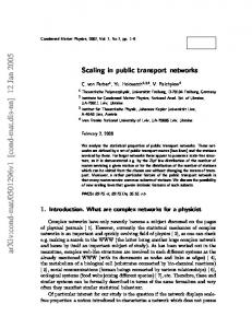
3.5.2.1 Protection Switching In the case of protection switching, an alternative connection is pre-established and prereserved (pre-provisioned). Therefore, protection switching realizes the shortest disruption of the traffic, since no routing and resource allocation is required after failure detection. In the SDH standardization the maximum allowed switching time of protection switching mechanisms is defined to be 50ms [ITU-T G.841]. Depending on the recovery scope, the alternative connection is either switched at the source and target network element (global protection or path protection), or locally at the network element adjacent to the failure (local protection or link protection). Many publications deal with survivable network design using protection switching mechanisms [Wu-1992, Wu-1995]. A good overview of protection mechanisms is given in [Ramamurthy-1999-I]. Below the generic characteristics of protection mechanisms are given independently of a specific network technology. Dedicated Protection In case of dedicated protection, the protection resources are used dedicatedly to the corresponding working connections. There are two dedicated protection schemes: 1+1 (one plus one) and 1:1 (one for one) protection. In Figure 3.3 both dedicated protection schemes are compared. The primary path is called working or active path (a). The secondary, alternative path is called protection or backup path (b). In 1+1 protection, the traffic is simultaneously transported over the working and protection path. In case of the failure, the target node only has to select the incoming traffic from the alternative path. With this combination, hitless recovery is possible. In [Iselt-1999] several protocols for hitless switching are analyzed. In case of 1:1 dedicated protection, the traffic is switched to the backup path 'b' only after a failure is detected on the active path 'a'. Under normal conditions, the backup resources can be used for the transport of low-priority preemptive traffic, so-called extra traffic. 1+1 dedicated protection source
+
a
1:1 dedicated protection target
a
source
b
b splitter
+
switch a b
target
switch
switch a b
Figure 3.3: 1+1 and 1:1 protection switching
46
3 - INTEGRATED MULTILAYER RESILIENCE FRAMEWORK
Shared Protection With shared protection the spare resources are not dedicated for the recovery of a specific connection, but can be shared by multiple connections for different failure scenarios. Figure 3.4 illustrates the concept of shared protection. dedicated protection
shared protection
a1
a1
b1
b1
b2
b
b2 a2
a2
Figure 3.4: Dedicated and shared protection On the link E-F the sum of the capacity of the two working connections A-B-C-D and G-H-I-D has to be reserved for the dedicated protection. In case of shared protection, only the larger capacity of A-B-C-D or G-H-I-D has to be reserved. In connections with equal capacity C are used, dedicated protection requires 2·C spare resources on link E-F and 6·C spare resources altogether for the protection of the two connections. With shared protection, the required spare resources are 1·C on the link E-F, and 4·C for the full connections. Because of the sharing of the spare resource, shared protection has better resource efficiency than dedicated protection. On the other hand, it requires a more complex signaling mechanism for the activation of the alternative connection. Shared protection mechanisms are common for ring topologies, where the spare resources are provided by additional fibers used only for protection traffic and extra traffic. 3.5.2.2 Restoration In the case of restoration, an alternative path is calculated and established on-demand after the detection of a failure. Since the calculation of alternative routes and the signaling and resource reservation of a new connection are time-consuming, restoration mechanisms are considerably slower than protection mechanisms. However, the restoration is also more resource efficient, since the spare resources can be used for the recovery of different working connections, provided these don’t share the same working resources. The recovery path is established using distributed restoration schemes after detecting the failure. There are several restoration mechanisms published, like the Selfhealing Network (SHN) [Grover-1987], FITNESS [Yang-1988], or RREACT [Chow-1993]. A good introduction to the characteristics of restoration mechanisms is given in [Ramamurthy-1999-II]. In general, restoration mechanisms search for a suitable backup path using distributed flooding mechanisms. Depending on the scope of the recovery mechanism, local or global, the node upstream of the failure or the source nodes of affected connections broadcast reservation messages on all outgoing links with enough spare capacity. When a broadcast message reaches the destination node, this node
3 - INTEGRATED MULTILAYER RESILIENCE FRAMEWORK
47
responds with an acknowledgement message. Either the restoration is complete, when the acknowledgement message reaches the source node (2-phase algorithm), or the source node has to send a confirm message downstream to the destination node (3-phase algorithm). protection
restoration a
a
before failure
b
a
a
after failure
b
b
Figure 3.5: Protection and restoration As an alternative to a flooding procedure, the upstream switching node can use a constraints based routing mechanism to calculate the full restoration route. A prerequisite for this approach is that the nodes have a full view on the network including the available capacity on the links. Such a mechanism can be used for example in MPLS networks. Since the calculation of new routes and the signaling and the resource reservation of a recovery path are time-consuming, restoration is considerable slower than protection mechanisms. However, restoration concepts are also more cost efficient, since the spare resources in the network can be shared for different failure scenarios. 3.5.2.3 Reconfiguration The restoration mechanisms cannot achieve optimal resource efficiency, since they use distributed mechanisms, which haven't a full view of the network. With centralized failure reconfiguration optimal resource efficiency can be achieved. The central network management has a full view of the current state of the network at the time of a failure. The state of the network includes the network topology and dimensioning, but also the full routing of working connections and the working and spare resources on each link. With this information, the centralized recovery can compute an optimized reconfiguration of the network. The drawback of the centralized recovery is of course the slow recovery from failures in the time scale of several minutes. This is due to the fact that a node controller has a delay time to collect alarms and failures within the node and to filter the root failure. The filtered alarm messages must then be sent over a signaling network to the network management system (NMS). The NMS may receive alarm messages from many nodes,
48
3 - INTEGRATED MULTILAYER RESILIENCE FRAMEWORK
and has to collect, filter and correlate these alarm messages to find the root cause of the failure. Only then the NMS can compute alternative routes for affected connections. 3.5.2.4 Rerouting The rerouting mechanisms work at the service level. Rerouting, or dynamic rerouting, tries to reconnect a connection after it failed. In IP networks rerouting is an inherent capability of the hop-by-hop routing of IP packets. If a router detects the failure of a neighbor router or attached link, it re-computes its routing tables and forwards all subsequent packets on the alternative route. In addition, the changed network topology is notified to all adjacent nodes. In case of OSPF, this is done with so-called Link State Advertisements (LSAs).
3.5.3
Recovery Topology
The recovery mechanisms can operate in different network topologies. Ring networks are well suited for protection mechanisms, since they are the simplest form of a twoconnected network. Recovery mechanisms for ring networks are described in [Eberspächer-1998]. One ring direction is used for the working traffic between source and destination, while the protection path is routed in opposite directions. In addition to two-fiber ring systems also four-fiber ring recovery mechanisms are possible. Protection mechanisms can also be used in mesh networks. Additionally, mesh network topologies also support restoration mechanisms. In [Grover-1998,Grover-2000], W.D. Grover introduced the concept of p-cycles, which is based on protection cycles (overlay ring structure) working in a mesh network, utilizing the advantages of both, ring and mesh topologies. In [Schupke-2002] the p-cycle concept is applied to WDM networks. Figure 3.6 illustrates the three recovery topology alternatives. ring
hybrid (p-cycle)
mesh
a
a
b
a
b
b
Figure 3.6: Recovery topology
3.5.4
Recovery Level and Recovery Scope
The recovery level refers to the vertical sublayer a mechanism is working at, the path layer or the multiplex section or line layer (also called link layer). The terms recovery level (path and link) and recovery scope (global, local, and regional or segment) are often used ambiguously.
3 - INTEGRATED MULTILAYER RESILIENCE FRAMEWORK
49
The recovery scope refers to the horizontal, i.e. the geographical extension of the recovery mechanisms. In case of a local recovery scope the recovery switching is done in the nodes adjacent to the failure, while in global recovery the switching is done at the connection end-points (e.g. mesh restoration). With path protection, each connection (e.g., a OCh carrying a lightpath) is switched at its endpoints. With link protection the multiplexed signal transmitted over a link (e.g. OMS with tens of wavelength) is switched at the same time (at multiplex section or line level). Therefore, path protection refers at the same time to the recovery level (connection) and to the recovery scope (global). The commonly used terms path restoration and link restoration refer both to a recovery at path level; path restoration switches each affected connection at the connection endpoints, while in case of link restoration each affected connection is restored at the nodes adjacent to the failure. Therefore, the commonly used term link restoration in fact specifies a local restoration at path level. To avoid ambiguity and to put emphasis on the difference between link protection and link restoration, in this work the terms global, regional and local restoration are used for a distributed, on-demand recovery of affected connections. An intermediate recovery scope is the segment recovery. In Figure 3.7 a special case is shown where the protection-switching node (PSN) B is upstream of the failure and the protection merge node (PMN) D is the endpoint of the connection. path
link active connection 1 (A-D)
a1
a1
backup connection 1
b1 a2
a2
b2
active connection 2 (B-E) backup connection 2
global
segment / regional
local
a1
a1
a1 b1 a2 b2
b
b1 a2 b2
Figure 3.7: Recovery scope
a2
50
3 - INTEGRATED MULTILAYER RESILIENCE FRAMEWORK
3.5.5
Recovery Switching Operation Modes
3.5.5.1 Switching type: Unidirectional versus bidirectional switching Two operation modes for recovery mechanisms exist for the recovery switching in case of failures affecting only one transmission direction. Such failures occur for example due to transmission laser outages. With unidirectional switching, only the affected direction of the failed traffic is recovered in case of unidirectional failures. In case of bidirectional switching, both, the affected and the unaffected direction of traffic affected by a unidirectional failure are recovered. For bidirectional switching, a protection switching protocol is required to control the switching operation. For ATM and SDH networks, this protection switching control protocol is called Automatic Protection Switching (APS) protocol. In case of unidirectional switching, only the sink node controls the switching operation, so no switching protocol is required. Therefore, unidirectional switching is less complex to implement and can operate faster. Unidirectional and bidirectional switching are also termed single ended vs. dual ended switching, respectively. Figure 3.8 illustrates the two switching modes. Unidirectional switching
Bidirectional switching
unidirectional failure
unidirectional failure
before failure
after failure
Figure 3.8: Unidirectional and bidirectional switching 3.5.5.2 Revertive / non-revertive operation The revertive and non-revertive operations relates to the behavior of recovery mechanisms, after the network impairment (e.g., cable cut) is physically repaired. In revertive operation, the recovered traffic is switched back to the original path automatically after the failure is repaired. In non-revertive operation, manual reaction is required to switch back the recovered traffic to the original path.
3 - INTEGRATED MULTILAYER RESILIENCE FRAMEWORK
51
3.5.5.3 Extra-traffic supported If in failure-free operation no traffic is transported over the spare resources, i.e. in case of 1:1 dedicated protection, shared protection and restoration, the spare resources may be used for low-priority, preemptive traffic. Supporting extra-traffic requires a sophisticated and more complex recovery protocol than recovery mechanisms without extra traffic support. The recovery protocol must take care that the extra traffic is preempted before the affected working traffic is switched to the spare resources. For ATM and SDH protection switching mechanisms, this preemption is performed by the APS protocol. Since failures are a rare event in a network, most of the time the spare resources are not used. Therefore it is economically recommendable to use these network resources, in spite of the additional complexity of the recovery control protocol.
3.6
State of the Art of Recovery Mechanisms
A large number of recovery mechanisms for the different network technologies are standardized or published in conferences and journals. For conciseness reasons, an exhaustive description of all recovery mechanisms cannot be given here. Instead an overview of some selected mechanisms is given. The characteristics of the individual mechanisms are highlighted and the advantages and drawbacks of recovery mechanisms in the corresponding technology are discussed in general.
3.6.1
ATM Recovery Mechanisms
ATM recovery mechanisms with distributed control are classified and evaluated in [Edmaier-1996]. A more recent survey on architectures for ATM network survivability is contained in [Kawamura-1998]. Since 1999, ATM protection switching mechanisms are standardized by the ITU in [ITU-T I.630]. A special case for 1+1 protection switching for a cell-based physical layer, which allows hitless switching, is standardized in [ITU-T I.480]. In this section the main characteristics of ATM protection switching and restoration mechanisms are presented, and the failure detection and signaling methods specified. OAM Functions The defect and failure detection and notification and the activation of recovery mechanisms in the ATM layer are realized using specific OAM (Operation, Administration, and Maintenance) cells [ITU-T I.610]. According to the five layers of the B-ISDN reference model, five hierarchical OAM flows F1 top F5 are defined are defined (see Table 3.4).
52
3 - INTEGRATED MULTILAYER RESILIENCE FRAMEWORK
OAM level
Network level
Network layer
F5 F4
Virtual channel level Virtual path level
ATM layer
F3 F2 F1
Transmission path level Digital section level Regenerator section level
Physical layer
Table 3.4: OAM levels The bi-directional F4 and F5 management flows use in-band OAM cells, which have pre-assigned VCI (Virtual Connection Identifier) and PTI (payload type identifier) values. In case of SDH-based transmission, the F1, F2, and F3 flows are transported in overhead bytes. In addition to the vertical hierarchy, F4 and F5 flows can either cover an entire network connection (end-to-end flow) or a part of a connection (segment flow). Table 3.5 lists the ATM OAM cells defined in [ITU-T I.610]. OAM cell CC LB AIS RDI APS
Type Continuity Check Loopback Alarm Indication Signal Remote Defect Indication Automatic Protection Switching
Function Failure detection Failure localization Failure notification Failure notification Recovery protocol
Table 3.5: OAM cell types Protection Switching Mechanisms ITU-T recommendation [ITU-T I.630] defines mechanisms for 1+1 and 1:1 bidirectional protection switching as well as 1+1 unidirectional protection switching. The description of the mechanisms includes the trigger mechanism, a hold-off time mechanism to delay recovery actions, and the protection switching control protocol. For the protection mechanisms a revertive and non-revertive operation is defined. The 1:1 operation is supported with and without extra traffic. The protection switching can be performed on either individual VP/VC connections, or on VP/VC protection groups. The VC/VP protection group alleviates the problem, that a large number of VP/VC connections can be affected by a single failure. Figure 3.9 shows the temporal model to evaluate ATM protection switching performance [ITU-T I.630]. The model is based on a general temporal model for restoration times defined in [ITU-T M.495].
3 - INTEGRATED MULTILAYER RESILIENCE FRAMEWORK
53
Network impairment SF or SD trigger Start of protection switching operation Last control signal or command received Protection switching operation complete Protected traffic fully restored T1
T2
T3
Tc
T4
Time t
T5
Tt
T1: Fault detection time
Tr
T2: Hold-off time T3: Protection switching operation time
Tc: confirmation time Tt: transfer time Tr: protected traffic restoration time
T4: Protection switching transfer time T5: Recovery time (verification, synchronization)
Figure 3.9: Protection switching timing model [ITU-T I.630] In recommendation [ITU-T I.480] a 1+1 protection switching mechanisms is defined for cell-based physical layers (as opposed to SDH/SONET-based physical layers), which provides a hitless protection switching (without signal disruption) between two sources and sinks of F3 OAM flows. The hitless switching is realized by duplication and synchronization of the two signal flows using sequence numbers in the OAM F3 cell flow. At the sink node one signal is selected and forwarded. Hitless protection switching mechanisms and their synchronization algorithms are also studied in [Iselt-1999]. Restoration Mechanisms So far no distributed restoration mechanism is standardized for ATM. However, a number of restoration mechanisms is studied and published in literature. The predominant property of ATM restoration mechanisms is the ability to pre-establish backup paths using zero capacity VPs (e.g, [Kawamura-1994, Anderson-1994]). Restoration schemes that use pre-defined backup VPs are called preplanned (BackupVP) Self-Healing Network (SHN) schemes [Kawamura-1998]. In [Kawamura-1995-b] the preplanned SHN schemes are compared to SHN restoration schemes based on flooding mechanisms.
3.6.2
SDH and SONET Recovery Mechanisms
With the resilience framework defined in the previous chapters, SDH (and SONET) recovery mechanisms are categorized in protection and restoration mechanisms, which will be briefly discussed in the following.
54
3 - INTEGRATED MULTILAYER RESILIENCE FRAMEWORK
3.6.2.1 Restoration Mechanisms W. D. Grover first introduced the Self-Healing Network (SHN), which realizes distributed restoration mechanism for DXC-based networks [Grover-1987]. Since then a number of publications deal with algorithms for path or link restoration for SDH (or for circuit-switched networks in general) and evaluate the spare-capacity utilization of different approaches [Chow-1993, Herzberg-1995, Iraschko-1996, Yang-1988]. For example, in [Iraschko-1996] the authors show that path restoration achieves 19% lower spare capacity utilization than link restoration. The algorithms to find suitable restoration paths were introduced in Section 3.5.2.2. 3.6.2.2 Protection Mechanisms SDH protection mechanisms are standardized in [ITU-T G.841]. Detailed descriptions of the mechanisms can be found in [Wu-1992, Ramaswami-2002, Wu-1995, PANEL-D2a]. Table 3.6 gives an overview of the most common protection mechanisms defined by the ITU-T and by ANSI-T1. The recommended target for the restoration time of SDH/SONET protection switching mechanisms is 50ms [ITU-T G.841]. ITU-T
ANSI T1
Level
Topology
MSP (1+1, 1:1, 1:N ) 2-fiber/4-fiber MS-SPRing
Line protection BLSR
Span (MS) Link (MS)
Point-to-point Ring
SNCP/mesh SNCP/ring
Path protection UPSR
Path (HOP, LOP) Path (HOP, LOP)
Mesh Ring
Abbreviations APS BLSR HOP LOP MS MS-DPRing MS-SPRing MSP UPSR ULSR SNCP
Automatic Protection Switching Bidirectional Line Switched Ring Higher Order Path Lower Order Path Multiplex Section Multiplex Section Dedicated Protection Ring Multiplex Section Shared Protection Ring Multiplex Section Protection Unidirectional Path Switched Ring Unidirectional Line Switched Ring Subnetwork Connection Protection
Table 3.6: SDH / SONET Protection Mechanisms The table classifies the SDH protection mechanisms depending on the recovery level (span, link, and path) and recovery topology (ring, mesh).
3 - INTEGRATED MULTILAYER RESILIENCE FRAMEWORK
55
Linear Multiplex Section Protection (1+1, 1:1, 1:N APS) The Linear Multiplex Section Protection (MSP) mechanism is called line protection in ANSI-T1 terms. In contrary to the 1+1 and 1:1 protection switching introduced in Section 3.5.2.1, SDH linear MSP is applicable to spans (point-to-point networks) only. In case of 1+1 MSP, one working fiber is protected with one dedicated protection fiber and the traffic is transmitted over both fibers simultaneously. In normal operation mode, the sink node forwards the signal from the primary fiber. In case of a failure or signal degrade the sink node can immediately switch to the alternative fiber. The 1+1 MSP has a very low complexity and achieves very fast recovery times. On the other hand, the mechanism requires 100% of spare resources. 1+1 MSP is generally operated in a unidirectional switching mode. In case of 1:1 MSP, one protection fiber is dedicated to one working fiber, but the traffic is transmitted on the protection fiber only in case of a failure. This allows the transmission of extra traffic on the protection fiber, but requires a more complicated recovery switching protocol. 1:1 MSP is generally operated in a bidirectional switching mode. In case of 1:N MSP, N working fibers share a single protection fiber. The APS protocol controls the recovery switching and takes care, that the protection fiber is not used for the recovery of more than one working fibers at the same time. 1+1 MSP
1:1 MSP
source + splitter
target
working fiber protection fiber
splitter
protection fiber
switch
target
working fiber
target
working fiber
switch
source +
source protection fiber
switch
source
switch
target
working fiber switch
protection fiber
switch
1:N MSP source
target working fiber #1 working fiber #2 working fiber #N protection fiber switch
Figure 3.10:
switch
SDH Linear Multiplex Section Protection
SDH/SONET Self-Healing Rings SDH and SONET networks with ring structures are currently the most commonly deployed network infrastructure of telecommunication operators. One reason for this is
56
3 - INTEGRATED MULTILAYER RESILIENCE FRAMEWORK
that recovery mechanisms were standardized and available for SDH/SONET Add/DropMultiplexers. The SDH Multiplex Section Shared Protection Ring (MS-SPRing) and the SONET Bidirectional Line Switched Ring (BLSR) architecture is a shared protection scheme and operates at link level. The MS-SPRing architecture uses a bidirectional ring with two or four fibers where working traffic is transmitted over both directions of the ring – clockwise and counter-clockwise (Figure 3.11). The protection capacity of the ring is shared by all traffic on the ring. The shared protection mechanism allows the transmission of extra traffic when no failure is present. For the control of the bidirectional protection switching and preemption of extra traffic, an APS protocol is defined. The MS-SPRing APS signals are transported in the K1/K2 bytes of the SDH/SONET overhead. In the two-fiber configuration half the capacity of each fiber is used for working traffic and the other 50% for protection traffic (Figure 3.11). This configuration only supports bidirectional ring switching. In the four-fiber configuration there is for each direction one fiber for working traffic and one fiber for protection traffic (Figure 3.12). The four-fiber configuration supports bidirectional ring switching in case of cable and node failures and additionally span switching in case of unidirectional failures. A detailed description of the MS-SPRing architecture and the MS-SPRing APS control protocol is given in [Wu-1992] and [Ramaswami-2002]. 2-fiber MS-SPRing (BLSR-2)
B
A
F
E
C
D fiber with 50% working and 50% protection traffic
Figure 3.11:
Two-fiber MS-SPRing
3 - INTEGRATED MULTILAYER RESILIENCE FRAMEWORK
57
4-fiber MS-SPRing (BLSR-4)
A
B
C
unidirectional fiber cut
F
E
D
A
B
C
bidirectional cable cut
F
E
D
fiber with working traffic fiber with protection traffic
Figure 3.12:
Four-fiber MS-SPRing
Subnetwork Connection Protection (SNCP) The Subnetwork Connection Protection architecture supports ring and mesh network structures. In SONET standards the corresponding recovery architectures are called Path Protection for mesh networks and Unidirectional Path Switched Ring (UPSR) for ring networks. In ring networks working traffic is sent unidirectional over the ring. That means, upstream and downstream traffic are traversing different portions of the ring (Figure 3.13). After the detection of a failure, the failure information is notified to the source and sink nodes of the affected connections using an APS protocol. The affected connections are switched at the end nodes using unidirectional protection switching. In the 1:1 operation, extra traffic is supported and must be preempted in case of failures.
58
3 - INTEGRATED MULTILAYER RESILIENCE FRAMEWORK
SNCP ring (UPSR)
A
B
C
F
E
D fiber with working traffic fiber with protection traffic
Figure 3.13:
3.6.3
SNCP ring (UPSR)
OTN Recovery Mechanisms
3.6.3.1 General considerations By using optical layer protection, significant cost savings can be realized compared to the protection of client layers of the optical network [Ramaswami-2002]. An additional advantage of optical layer protection is the bulk protection of physical failures instead of protecting many individual client signals. The drawback is of course that the smallest recovery granularity of the optical layer is one lightpath. Moreover, protection routes in the optical layer have length limitations due to optical attenuation and dispersion budgets. Optical layer recovery alone cannot recover failure of client layer equipment and client connections terminating in failed optical nodes. If optical layer recovery is used in addition to client layer recovery, an additional degree of resilience can be achieved. Single failures in the optical layer can be recovered by the optical layer alone. Secondary failures and client layer failures can be recovered in the client layer. However, this requires careful attention to interworking schemes. A detailed framework for multiple failure recovery is defined in Section 3.8 and the multilayer recovery framework is defined in Section 3.9. 3.6.3.2 OTN Protection Switching Mechanisms Optical layer recovery mechanisms operate either at the Optical Multiplex Section (OMS) or at the Optical Channel (OCh). The first corresponds to link recovery, the second to path recovery mechanisms. Table 3.7 gives an overview of optical protection mechanisms defined in [Ramaswami-2002]).
3 - INTEGRATED MULTILAYER RESILIENCE FRAMEWORK
59
ITU-T
Type
Level
Topology
OMSP (1+1, 1:1)
Dedicated, shared
Span (OMS)
Point-to-point
OMS-DPRing OMS-SPRing
Dedicated Shared
Link (OMS) Link (OMS)
Ring Ring
OCh-DPRing OCh-SPRing OCh-SNCP
Dedicated Shared Dedicated
Path (OCh) Path (OCh) Path (OCh)
Ring Ring Mesh
Abbreviations OMS-DPRing OMS-SPRing OMSP OCh-SNCP
Optical Multiplex Section Dedicated Protection Ring Optical Multiplex Section Shared Protection Ring Optical Multiplex Section Protection Optical Channel Subnetwork Connection Protection
Table 3.7: OTN Protection Mechanisms The optical layer protection mechanisms are similar to their SDH and SONET counterparts. However, their implementation is substantially different. In addition to [Ramaswami-2002] a good discussion of implementation aspects of optical layer protection mechanisms is given in [Gerstel-2000-b]. A difference, which must be considered for the implementation, is the costs of optical transmission equipment, which grows which the number of wavelengths to be multiplexed and terminated. In addition, optical paths are length constraint due to physical link budgets. This is especially important for link based ring mechanisms, where the protection path is traversing the full ring except for the failed ring. A connection, which traverses half the ring under normal conditions, can be almost three times as long after link protection switching. If no wavelengths conversion is possible, the wavelength continuity must be complied with also for the protection path. 3.6.3.3 OTN Restoration Mechanisms Using distributed control architectures defined for Automatically Switched Optical Networks (ASON) and for the Generalized Multiprotocol Label Switching (GMPLS) architectures fast optical mesh restoration is feasible. In the ASON architecture, an end-to-end path restoration mechanism can be implemented. Since ASON supports automatic end-to-end path provisioning, this mechanism can be used for an end-to-end path restoration with 100ms restoration times [FASHION-D1]. Upon detection of a failure in the end nodes of optical lightpaths, the control plane can automatically set up an alternative connection. Since the distributed control plane has information about the full network, the restoration can use a constraint based routing instead of flooding mechanisms. Optical restoration mechanisms for the GMPLS architecture are proposed in the IPO (IP-over-Optical) and CCAMP (Common Control and Management Protocol) workgroups of the IETF.
60
3.6.4
3 - INTEGRATED MULTILAYER RESILIENCE FRAMEWORK
MPLS Recovery Mechanisms
MPLS recovery is a key research issue in the IETF. Several IETF drafts and a framework proposal [Draft-Sharma] are discussed in the MPLS working group and present different recovery mechanisms. According to [Draft-Sharma] benefits from the MPLS Recovery are: • Finer recovery granularity (compared to Layer-1 recovery) • Protection selectivity based on service requirements becomes possible • Efficient and flexible resource usage (e.g., recovery path may have reduced performance requirements) • Allows end-to-end protection of IP services • Uses lower layer alarm signals (contrary to current IP rerouting) Several functions are required to provide resilience in a MPLS network: • Fast and reliable failure detection • Recovery framework - Selection of recovery options • Resilience provisioning and signaling - Traffic engineering aspects - Resilience-constrained LSP setup - Protection selectivity support Using the concept of the LSP the provisioning of resilience similar to classical link restoration or protection switching mechanisms is possible. Since MPLS LSPs are generally unidirectional the recovery mechanisms work unidirectional, too. The main options and parameters for MPLS recovery mechanisms defined in [Draft-Sharma] are the recovery model (protection switching, restoration, rerouting), the path setup (preestablished, pre-qualified, established-on-demand), the resource allocation (prereserved, reserved-on-demand), and the resource usage (dedicated-resource or extratraffic-allowed). Some sample recovery mechanisms and their applicable recovery options will be discussed and illustrated with some network examples in the following sections. 3.6.4.1 Protection Switching In the case of protection switching, the alternative LSP is pre-established and prereserved (pre-provisioned). That is why protection switching realizes the shortest disruption of the traffic. Depending on the recovery scope, the LSP is either switched at the ingress and egress LSR (path protection), or locally at the LSRs adjacent to the failure (local protection). Link Protection A protection switching scheme where recovery LSPs are pre-established for each link is often called MPLS Fast Reroute. Several different proposals are currently discussed in the IETF. The advantage of such a fast rerouting scheme is that no end-to-end failure
3 - INTEGRATED MULTILAYER RESILIENCE FRAMEWORK
61
notification and signaling is required for the protection switching. A node detecting a physical failure at its port may immediately switch the affected traffic to the recovery path. To reduce the number of recovery LSPs a node has to configure, a single recovery LSP could be configured to protect several LSPs running over the link and belonging to the same FEC.
C B A
p-LSP1
w-LSP F
E
G
D
p-LSP2 G
H
Figure 3.14:
p-LSP3
MPLS link protection (fast reroute)
Another method to setup an alternative label switched path to handle fast rerouting is proposed by Haskin [Draft-Haskin]. The mechanism is similar to a classical SDH MSSPRing mechanism. Figure 3.15 illustrates the mechanism. For each LSP an alternative recovery LSP is set up as indicated from the last-hop switch in reverse direction to the source of the working LSP and along a node-disjoint path to the destination switch.
C
B A
w-LSP E
G
Figure 3.15:
F
D
p-LSP H
G
MPLS segment protection (by Haskin)
When a failure is detected (1), the adjacent upstream node immediately switches the working LSP to the recovery LSP (2). The advantage of this approach is, that only a single protection-LSP must be set up, and the rerouting may still be triggered based on a local decision in the node directly upstream of the failure. Thus no recovery signaling is needed.
62
3 - INTEGRATED MULTILAYER RESILIENCE FRAMEWORK
Path Protection Protection switching schemes with global scope are called path protection. For each protected LSP a protection LSP is established either between the ingress and egress LSR (Figure 3.16), or between designated recovery-switching points (so-called segment protection). The switching LSR must be notified that an LSP failed, in order to switch the LSP to the protection LSP. The MPLS signaling protocols CR-LDP and RSVP-TE are extended to support such failure notification.
C
B A
w-LSP F
E G
Figure 3.16:
D
p-LSP H
G
MPLS path protection
Resource Allocation and Usage Several options are possible for the resource usage of the recovery path [Draft-Sharma]. In 1+1 ("one plus one") operation a copy of the working traffic is always transported over the recovery path. To recover from a failure the egress LSP must only select the incoming traffic from the protection LSP instead of the working LSP. No signaling is required in this case. In 1:1 ("one for one") operation, the working traffic is only switched to the recovery LSP if a failure occurred on the working LSP. Depending on the selected resource usage, dedicated or shared, the recovery LSP may be used only to recover a single working LSP, or it may be used to recover different LSPs with the same LSP end points (see also Figure 3.16). In the second case, the working LSPs follow disjoint routes through the network. Otherwise a single failure could disrupt both working paths, and there wouldn't be sufficient protection resources to recover both paths. If a 1:1 resource allocation is used the recovery LSP may additionally carry low-priority, pre-emptible traffic - so-called extra-traffic - when no failure is present in the network. This extra traffic must be dropped if the LSP is needed for the recovery of a failed LSP. 3.6.4.2 Restoration (MPLS Rerouting) When deploying an MPLS rerouting scheme, recovery LSPs are established-on-demand after the detection of a failure. In contrary to classical IP rerouting, MPLS may utilize a fast hardware detection to decrease the recovery time needed to restore the affected traffic.
3 - INTEGRATED MULTILAYER RESILIENCE FRAMEWORK
63
In analogy to protection switching, the recovery can be done locally around the failed link or node, or globally starting at the ingress and egress LSP. Figure 3.17 illustrates global restoration, Figure 3.18 regional restoration, and Figure 3.19 local restoration in MPLS.
C
B A
w-LSP E
G
MPLS global restoration
C
B A
D G
H
Figure 3.17:
w-LSP E
G
F G
MPLS regional restoration
w-LSP
B
Figure 3.19:
C
F r-LSP
E G
D
r-LSP H
Figure 3.18:
A
F r-LSP
H
D G
MPLS local restoration
The recovery path is established using constraint-based routing and signaling protocols after detecting the failure. Since the calculation of new routes and the signaling and resource reservation of a new LSP are time-consuming, MPLS rerouting is considerable slower than protection mechanisms.
64
3.7
3 - INTEGRATED MULTILAYER RESILIENCE FRAMEWORK
Performance Evaluation of Resilience Concepts
Different evaluation methods and performance parameters can be used for the evaluation of resilience strategies. o Terminal pair availability analysis o Network availability analysis o Spare capacity planning and resource efficiency evaluation o Recovery time analysis o Recovery time performance simulation o Protocol simulation o Protocol complexity evaluation The performance evaluation methods mainly used in this work are the resource efficiency evaluation, recovery time analysis and protocol complexity evaluation. For the evaluation of the differentiated resilience architecture, resource efficiency based on traffic engineering methods and the recovery time are evaluated using graph theory analysis. For multilayer recovery analysis a protocol simulation using a highly detailed modeling of the simulated network elements was performed, which at the same time also allows a discrete-time event-oriented performance simulation to evaluate the recovery time of multilayer interworking strategies. In the following subsections, the methods for spare capacity planning, resource efficiency evaluation and recovery time analysis are briefly introduced.
3.7.1
Spare Capacity Planning
The provisioning of spare resources for network survivability directly translates to increased network costs. Depending on the used recovery model and options, the required normalized spare resource costs may be between 150% for path restoration methods [Johnson-1996] and 200 – 300% for protection against single link or node failures [Grover-2000]. If survivability guarantees against multiple failures are required, the spare resource requirements may be even higher. An introduction to network planning including spare capacity dimensioning is contained in [Eberspächer-1998]. The planning of spare resources has been studied extensively in literature (e.g, [Iraschko-1996, Caenegem-1997-a, Caenegem-1997-b, Herzberg-1994, Herzberg-1995, Herzberg-1997, Grover-1991]). The publications covering the planning of spare resources usually start with a greenfield scenario and optimize the network capacity using graph theory and optimization techniques like Integer Linear Programming (ILP) or heuristics. The result of the planning process is a capacitated network with resources for working and protection/restoration traffic.
3.7.2
Resource Efficiency Evaluation
In the recovery efficiency evaluation used in this thesis a traffic engineering approach is used instead of a network planning approach: instead of optimizing the network capacity
3 - INTEGRATED MULTILAYER RESILIENCE FRAMEWORK
65
a capacitated network is used as starting point. The backup resources required for a given resilience strategy are evaluated using graph theory procedures and heuristics for the routing of the primary and secondary paths. In contrast to the spare capacity planning, only the resources dedicated to the recovery of working traffic are considered, but not free network capacity. In chapter 4 this traffic engineering approach is explained in more detail for the evaluation of the RD-QoS architecture.
3.7.3
Recovery Time Analysis
In [ITU-T M.495] a generic temporal model for service restoration is defined. Based on this model a restoration temporal model specific for ATM protection switching is defined in [ITU-T I.630]. A similar model for the recovery time cycle in MPLS networks is defined in [Draft-Sharma]. Figure 3.20 illustrates this recovery cycle model. Network impairment Fault detected Start of notification Start of recovery operation Recovery operation complete Traffic fully restored T1
T2
T3
T1: Fault detection time T2: Hold-off time
T4
T5
Time t
T4: Recovery operation time (switching time) T5: Restoration time (verification, synchronization)
T3: Notification time
Figure 3.20:
Recovery cycle model (based on [Draft-Sharma, ITU-T I.630])
The recovery time analysis model used in this work is based on the above recovery cycle model and on the analysis model for the restoration times published in [Ramamurthy-1999-II]. However, the latter model was extended in some parts. In the following the recovery timing model and the extensions to the work of Ramamurthy is explained. The following list summarizes the extensions considered in this thesis compared to [Ramamurthy-1999-II]. Adaptation to MPLS recovery mechanisms. Relation to restoration time model and MPLS recovery cycle [Draft-Sharma]. Queuing and sequential processing of control messages for multiple recovered connections. In [Ramamurthy-1999-II] it is assumed that the message queuing time is included in a fixed message processing time. A route calculation time for restoration schemes using constraint based explicit routing instead of a flooding mechanism.
66
3 - INTEGRATED MULTILAYER RESILIENCE FRAMEWORK
Use of real link lengths for calculation of propagation delay. [Ramamurthy-1999-II] assumes fixed link propagation delays of 400µs corresponding to a link length of 80 km. Additional switching time in destination node for restoration mechanisms. Analysis of multiple affected connections (ranging from a few to several thousand connections). The following notation and parameter values are used for the timing model. n:
Number of nodes from the node upstream of the failure (FUR) to the source node of the flow (I-LSR). m: Number of nodes from the label merge router (LMR) to the target node of the flow (E-LSR). b: Number of links on the backup route of a failed connection from the recovery switching node to the recovery merging node. f: Flow/LSP index. T1: Failure detection time. Depending on the used failure detection mechanisms, highly different values are possible for the failure detection time. In the case studies this value is assumed to be 20 ms. T2: Hold-off time is assumed to be 0 ms Notification time is calculated T3: Recovery operation time is calculated T4: T5: Traffic restoration time is calculated D: Message processing time in the node is 10µs as in [Ramamurthy-1999-II]. However, in contrast to [Ramamurthy-1999-II] in this thesis the queuing and processing of multiple control messages is modeled with a simple sequential processing of individual flows. That is, the processing of the second flow is finished after 2·D, and the processing of the flow f is finished after f·D. P: Propagation delay on a link is 5µs per km, corresponding to 250µs for a link length of 50km Length of link i in km Li: C: Time to configure, test and setup a forwarding table (switching time). Values between 1 ms and 10 ms are considered for C in the case studies. In contrast to [Ramamurthy-1999-II] it is assumed, that the switching is in parallel to the message processing. A LSR needn't wait for the completion of the switching before the message (e.g., backup LSP setup) can be forwarded. R: Time to calculate new constraint based backup route. This time is depending on the size of the network and on the number of constraints. A value of 2 ms is assumed for the route calculation. For the constraint based routing, the route must be calculated for each individual LSP. The link propagation time is calculated for the traversed edges using the physical link length of the considered network scenarios. In the model, the following notation is used for the link propagation:
3 - INTEGRATED MULTILAYER RESILIENCE FRAMEWORK
n
∑ (LiP) i=1
67
Propagation time over the set of edges En. The time is composed of the sum of the link lengths of all traversed edges multiplied with the propagation delay. b=5 b=3
n=2
m=2
Recovery model
n
b
m
Path protection / restoration (dashed line) Link protection / restoration (dotted line) Segment protection by Haskin (not shown) Regional restoration (not shown)
2 0 0 0
5 3 7 4
0 2 0 0
Figure 3.21:
Relation between restoration time parameters n, m and b
Figure 3.21 shows the relation between the parameters n, m and b. In the following sections the timing models for selected recovery mechanisms are defined with a focus on MPLS networks. 3.7.3.1 Protection Switching Path Protection After the detection of a failure the upstream node sends a failure detection message to the I-LSRs of all affected flows traversing the failed link. The source nodes switch the failed LSPs to the preconfigured protection LSP by reconfiguring the label forwarding table. No additional signaling is required since MPLS LSPs are unidirectional and the protection LSP is predefined. The intermediate LSRs needn't perform any functions and in the label merge router (LMR) the protection and the working traffic are merged automatically by the preconfigured label forwarding table. In MPLS, the labels of the backup paths can already be preconfigured in the label forwarding table, since the capacity of the LSP is not exclusively reserved for the flow. Instead, if the backup path is not used, the capacity is available automatically to other traffic (including low priority, extra traffic). Preemption of the low priority traffic on the backup route is performed implicitly in MPLS by utilizing a lower holding priority for the extra traffic [RFC3212]. The restoration process is finished when the traffic sent from the I-LSR over the backup LSP reaches the E-LSR. Thus the total restoration time for a flow f using a path protection scheme in MPLS is:
68
3 - INTEGRATED MULTILAYER RESILIENCE FRAMEWORK
Tr (f)= T1 + T3 + T4 + T5 n
b
i=1
i=1
Tr (f) = T1 + [ f ·D + n ·D + ∑ (Li ·P) ] + C + ∑ (Li ·P) T1 is the fixed failure detection time in the router upstream of the failed link (FUR). The notification time is composed of a sequential message processing in the FUR and the message propagation and processing until the notification message reaches the I-LSR. In the I-LSR the LSP forwarding table is reconfigured. Link Protection The link protection timing model is similar to the path protection case. The main difference is that the signaling to the I-LSP is not applicable. Upon detection of the failure, the FUR must identify the failed LSPs and can then immediately switch the failed flows to the backup LSP. The restoration process is finished, when the traffic sent from the FUR over the backup route reaches again the E-LSR. b+m
Tr (f) = T1 + [ f ·D ] + C + ∑ (Li ·P) i=1 Segment Protection The segment protection timing model is almost identical to the link protection case, only the backup route is different. For the segment protection mechanisms defined by Haskin the backup route is usually much longer than the backup route in case of link protection. b
Tr (f) = T1 + [ f ·D ] + C + ∑ (Li ·P) i=1 3.7.3.2 Restoration The restoration time model is given for the global, local and regional MPLS recovery mechanisms described in Section 3.6.4.2. In contrast to [Ramamurthy-1999-II], where flooding based restoration mechanisms are assumed, restoration mechanisms with constraint based explicit routing in the LSRs are assumed here. Global Restoration The restoration time is composed of the failure detection time T1, the notification time T3, the switching time T4, and the restoration completion time T5. As with path protection, the notification time is composed of a sequential message processing in the FUR and the message propagation and processing until the notification message reaches the I-LSR. The switching requires a sequential constraint based route calculation. After the route calculation is finished, a backup LSP setup message is sent to the E-LSR using explicit routing. When the signal is sent back, the LSP forwarding table must be
3 - INTEGRATED MULTILAYER RESILIENCE FRAMEWORK
69
updated on every intermediate node. Since the message can be forwarded before the forwarding table update is completed, only one switching time (at the I-LSR) is added to the restoration time. Finally, the traffic must propagate from the I-LSR to the E-LSR. b
b
i=1
i=1
Tr (f)= T1 + [f ·D + n ·(P + D)]+[ f ·R+2·b·D+2· ∑ (Li ·P) +C]+ ∑ (Li ·P) Local Restoration With local restoration no failure notification is required. The FUR looks up the affected LSPs, computes the backup path for each failed LSP, and sends a backup LSP setup message to the router downstream of the failed link (FDR). When an acknowledgement message arrives back at the FUR the LSP can be switched to the alternative route. b
b+m
i=1
i=1
Tr (f) = T1 + [ f · D ] + [ f ·R + 2 · b ·D + 2 · ∑ (Li ·P) + C ] + ∑ (Li ·P) Regional Restoration With the exception of the traffic restoration on the backup path the regional restoration timing model is the same as in the link protection case. b
b
i=1
i=1
Tr f = T1 + [ f · D ] + [ f ·R + 2 · b ·D + 2 · ∑ (Li ·P) + C ] + ∑ (Li ·P)
3.7.3.3 Recovery Time Analysis The restoration time is calculated for a given set of expected failures, e.g. all single link failures. The expected time to restore is calculated as an average of the restoration time of all flows and all expected failures. Alternatively, the restoration ratio over time can be calculated, which indicates the ratio of recovered flows to the number of affected and recoverable flow over the time. The restoration ratio can be calculated for a single failure, or averaged over a given set of failures. This restoration time analysis is used for the performance evaluation of the RD-QoS architecture presented in Chapter 4.
3.8
Multiple Failure Recovery Framework
In Section 3.3 an overview of possible failure of a network is given, and in [Schupke-2001-a] network-wide significance of multiple failures as well as the vulnerability of different recovery mechanisms in a network is shown. In this section a framework for the recovery of multiple failures is defined.
70
3 - INTEGRATED MULTILAYER RESILIENCE FRAMEWORK
As already stated, recovery mechanisms are commonly classified into protection, restoration and reconfiguration according to two criteria: the time of the backup route calculation and the type of switching control instance. It should be noted that protection schemes are more vulnerable to multiple failures than restoration schemes since they use predefined recovery paths. If the primary failure in a network affects the protection path of a connection, the connection cannot be recovered if it is affected by a second failure. Secondly, if the original connection was affected by the first failure and was recovered using the protection path, an additional failure on the protection path cannot be recovered. Restoration schemes on the other hand are inherently more robust against complex multiple failure scenarios. The alternative path is either computed centrally or searched using a distributed flooding mechanism. Therefore, provided that enough spare capacity is available in the network, alternative paths can be found. The classification of recovery mechanisms takes only the behavior for single failures into consideration. In Figure 3.22 a framework is defined to classify recovery of multiple failures. Multiple Failure Recovery Approach Horizontal approach
Vertical approach
• Network partitioning • Pre-computed recovery (before first failure) • Re-computed recovery (after first failure) • Re-Restoration (After secondary failures)
Figure 3.22:
• Recovery at higher layer (Escalation strategy with hold-off time) • Recovery at lower layer (OMS-Restoration) • Central reconfiguration (by NMS with access to several layers)
Multiple failure recovery framework
Two approaches are distinguished: a horizontal approach, where the secondary failures are recovered at the same layer (but possibly with another recovery scheme) and a vertical approach, where secondary failures are recovered at another layer. A second criterion is, at which point in time the alternative route for secondary failure is computed (before primary failure, after primary failure, after secondary failure). The different options of the multiple failure recovery framework are discussed in the next sections.
3.8.1
Horizontal Approach
Network Partitioning A horizontal partitioning of the network in protected domains can be used to minimize the probability of multiple failures. Examples for network partitioning are multiple interconnected rings and p-Cycles.
3 - INTEGRATED MULTILAYER RESILIENCE FRAMEWORK
71
A main consideration to handle multiple failures is the computation of the route for recovery from a secondary failure in the presence of a primary failure. Three different options can be distinguished: Pre-Computed Recovery (Before First Failure) In case of pre-computed multiple failure recovery the alternative paths of secondary failures are calculated already before a primary failure occurs. This option is useful for primary protection or centralized restoration mechanisms. Practical approaches for this scenario are protection tables with multiple entries, where a node must select a protection entry, which is still available after a failure. In the planning process it must be considered, that the protection routes should be maximally disjoint to increase the probability that there is still a protection path available for an arbitrary failure scenario. A second approach is to compute for each node a second protection table for every single link and/or single node failure. After the first failure, all nodes load the corresponding secondary protection table. Re-Computed Recovery (After First Failure) In this case the alternative paths for working and backup paths affected by a primary failure are calculated after the primary failure occurrence. After the occurrence of a first failure, the nodes or the network management system compute for all affected working paths new protection paths and for all affected protection paths new alternative paths. The figure below illustrates this. In the left part of the figure the working path W-1 using the route F-G-H-D is affected by a failure and is switched over to the protection path P-1 using F-E-D. Since this connection is now vulnerable against secondary failures, a backup path P'-1 is recomputed for this connection, using for example F-G-B-C-H-D. In the right part of the figure the situation is shown where the backup path is affected by a failure (P-2). In this case the working path W-2 is also unprotected against secondary failures. Therefore the protection path P'-2 is re-computed. This multiple failure recovery option corresponds to a protection mechanism in the single failure scenario. The network is protected against multiple failures after a relatively short re-computation phase.
P’-1 W-1 P-1
Figure 3.23:
W-2 P-2 P’-2
Two scenarios for protection path re-computations
72
3 - INTEGRATED MULTILAYER RESILIENCE FRAMEWORK
Re-Restoration (After Secondary Failures) Corresponding to single failure restoration, the alternative route computation for secondary failures could be done on-demand after the occurrence of a secondary failure. Please remark, that in this case the primary recovery mechanism can also be a protection scheme.
3.8.2
Vertical Approach
In today's networks, different transport technologies can participate in the recovery of failure recovery. However, the layers would by default not coordinate themselves when attempting recovery from outages. On the one hand, server layer(s) are left unaffected by client layer failures for the most part. On the other hand, due to dependency on lowerlayer services, client layers are in most cases struck by failures on the layer(s) below, which inherently causes multiple simultaneous failures. Recovery at Higher Layer (Escalation Strategy with Hold-Off Time) Recovery in such systems with vertical separation may converge to a steady state relatively slow or not at all. A simple, but certainly sub-optimal solution is to introduce escalation tactics [Manchester-1999]. A server layer is given the opportunity to solve the problem during a certain period of time. When the hold-off timer expires, control is passed to its client layer if the measures had no effect so far, and so on. Further escalation or interworking strategies published in [Demeester-1999] are described in section 3.9. As an alternative, explicit failure messaging across layers could be introduced. Besides standardized failure types/messages, this would also include failure localization procedures. Based on knowledge about the capabilities of the given layers, recovery could be explicitly delegated or executed, respectively, by a generalized control plane. This is currently pursued by the GMPLS standardization effort, where the various transport technologies are logically merged to a uniform infrastructure layer [Draft-Lang] rather than attempting vertical messaging across layers. The standardization organization ANSI and the Optical Interworking Forum (OIF) also work on layer coordination [Gerstel-2000-b]. Recovery at Lower Layer (e.g. OMS-Restoration) A second option for a vertical multiple failure recovery approach works on two granularities, namely on path (optical channel or SDH/SONET signal) and line (WDM signal) layers, respectively. While the first occurring failure is quickly overcome on the fine-granular higher layer, another failure is repaired at the layer below, using optical crossconnects (OXCs). That way, there is no vulnerability anymore in the period between occurrence and repair of the first failure [Gerstel-2000-b]. A drawback is, that with the mechanism described in [Gerstel-2000-b] the switching of the lower layer recovery mechanism causes an additional short-term disruption of the already recovered connections.
3 - INTEGRATED MULTILAYER RESILIENCE FRAMEWORK
73
Central Reconfiguration (by NMS with Access to Several Layers) Such systems typically perform a kind of resource optimization on the network, trying to accommodate all demands with the current topological restrictions in mind. Therefore, a centralized entity re-computes and updates routing in the network. The NMS may have the advantage to access several layers for service restoration.
3.8.3
Multiple Failure Spare Capacity Planning
To be robust against multiple failures, enough spare capacity must be present in the network. This should be taken into regard already in the network planning process by including multiple failures into the anticipated failure scenarios. Instead of calculating the required spare capacity to restore the traffic only for single link or node failures, multiple failure scenarios should already be taken into account. Such additional multiple failure scenarios could include all double link and node failures as well as simultaneous single link and node failures.
3.9
Multilayer Recovery Framework
It is generally possible to reach the survivability requirements of network services with resilience mechanisms present at different layers, e.g. SDH, ATM, OTN and MPLS [Draft-Owens]. Moreover, these resilience mechanisms may even be in operation in multiple layers at the same time. The ACTS project PANEL [Demeester-1997] investigated the interworking of multilayer recovery mechanisms, and a multilayer recovery framework was defined and published in [Demeester-1999]. The multilayer framework, concepts and results of the PANEL project influenced a white paper on multi-layer survivability published by Lucent Technologies [Meijen-1999], which was presented as ANSI-T1 contribution T1A1.2/2000-008 in January 2000. This finally resulted in multi-layer survivability definitions in the ANSI-T1 Technical Report on Enhanced Network Survivability Performance [ANSI TR68]. The multilayer recovery framework considers the recovery mechanisms present in single layers, the planning of spare resources in multiple layers, the multilayer recovery strategy and interworking mechanisms.
3.9.1
Multilayer Resilience Considerations
Before selecting a multilayer resilience strategy, the benefits and drawbacks of resilience at the individual layers must be analyzed and some pitfalls with multilayer recovery are illustrated. 3.9.1.1 Recovery at Optical Layer Only A main advantage of the optical layer is the ability to detect failures very fast (, November 2001 Sharma, V., Hellstrand, F. (Editors) "A Framework for MPLSbased Recovery," Work in Progress, Internet Draft, draft-ietfmpls-recovery- frmwrk-04.txt, May 2002 Mannie, E., Papadimitriou D., et al., "Generalized Multiprotocol Label Switching Architecture", Internet Draft, Work in progress, draft-ietf-ccamp-gmpls-architecture-03.txt, August 2002. Eberspächer, Jörg, "Systemtechnische Grundlagen", in: "Handbuch für die Telekommunikation", V. Jung, H.-J. Warnecke (Eds), Springer Verlag Berlin, 1998 Jörg Eberspächer, Piet Demeester (Eds.), "Proceedings of the Second International Workshop on the Design of Reliable Communication Networks (DRCN 2000)", Herbert Utz Verlag, Munich, ISBN 3-89675-928-0, 2000 Edmaier, Bernhard, "Pfad-Ersatzschalteverfahren mit verteilter Steuerung für ATM-Netze", PhD Thesis, Institute of Communication Network, Munich University of Technology, Munich, 1996 ETSI EN 300 417, "Transmission and Multiplexing (TM), Generic requirements of transport functionality of equipment", October 2001 Eurescom Project P1012 – FASHION - Deliverable D1, "Switched Optical Networks: Architecture and Functionality", Jacques Robadey (Ed.), March 2002 Fumagalli, A. and Tacca, M., "Optimal Design of Optical Ring Networks with Differentiated Reliability (DiR)", International Workshop on QoS in Multiservice IP Networks, Rome, Italy, January 2001
140
[Gerstel-2000-a]
[Gerstel-2000-b]
[Ghani-2000]
[Grover-1987]
[Grover-1991]
[Grover-1998]
[Grover-2000]
[Gryseels-1998-a]
[Gryseels-1998-b]
[Herzberg-1994]
[Herzberg-1995]
[Herzberg-1997]
BIBLIOGRAPHY
Gerstel, O., Ramaswami, R., "Optical Layer Survivability: A Services Perspective", IEEE Communications Magazine, vol. 38 (2000), no.3, pp.104-113. Gerstel, O., Ramaswami, R., "Optical Layer Survivability - An Implementation Perspective", IEEE Journal on Selected Areas in Communications, vol.18, no.10, pp.1885-1899, October 2000. Ghani, N., Dixit, S., Wang, T. S., "On IP-over-WDM integration", IEEE Communications Magazine, vol. 38, no. 3, pp. 72-84, 2000 Grover, W.D., "The Selfhealing Network, A Fast Distributed Restoration Technique for Networks Using Digital Crossconnect Machines", Proceedings of IEEE GLOBECOM '87, Tokyo, Nov. 1987. pp.1090-1095. Grover, W.D., Bilodeau, T.D., Venables, B.D., "Near Optimal Spare Capacity Planning in a Mesh Restorable Network," Proceedings of IEEE Globecom '91, Phoenix, Arizona, Vol. III, pp. 2007-2012, December 1991. Grover, W.D., Stamatelakis, D., "Cycle-oriented distributed preconfiguration: ring-like speed with mesh-like capacity for selfplanning network restoration," in Proc. IEEE International Conf. Commun. (ICC '98), Atlanta, June 8-11, pp. 537-543. Grover, W.D., Stamatelakis, D., “Bridging the ring-mesh dichotomy with p-cycles”, (Invited Paper) in Proc. IEEE / VDE Design of Reliable Communication Networks (DRCN 2000), Munich, Germany, April 2000, pp. 92-104. Gryseels, Michael, Stuyve, K, Pickavet, M., Demeester, P., "Common pool survivability for meshed SDH-based ATM networks", Int. Symp. Broadband European Networks (SYBEN'98), Zurich, Switzerland, May 1998, pp. 267-278 Gryseels, M., Clemente, R. and Demeester, P., “Common pool survivability for ATM over SDH ring networks”, Proc. 1st Intl. Workshop on the Design of Reliable Communication Networks, Brugge, 1998. Herzberg, M. and Bye, S. J., "An Optimal Spare-Capacity Assignment Model for Survivable Networks with Hop Limits", Proc IEEE GLOBECOM '94, 1994 Herzberg, M., Bye, S. J., and Utano, A., "The Hop- Limit Approach for Spare-Capacity Assignment in Survivable Networks," IEEE/ACM Transactions on Networking, vol. 3, no. 6, December 1995, pp. 775-784. Herzberg, M., Wells, D., and Herschtal, A., "Optimal Resource Allocation for Path Restoration in Mesh-Type Self-Healing Network," Proceedings of the 15th International TeletraÆc Congress - ITC 15, Washington, DC, 22-27 June 1997, pp. 351360, Elsevier Science B. V., 1997.
Bibliography
[Iraschko-1996]
[Iselt-1999]
[ITU-T E.800]
[ITU-T G.707]
[ITU-T G.709] [ITU-T G.803]
[ITU-T G.805] [ITU-T G.807] [ITU-T G.808]
[ITU-T G.841] [ITU-T G.872] [ITU-T I.311] [ITU-T I.321] [ITU-T I.326] [ITU-T I.361] [ITU-T I.380]
[ITU-T I.480]
141
R.R. Iraschko, M.H. MacGregor, W.D. Grover, "Optimal Capacity Placement for Path Restoration in Mesh Survivable Networks," IEEE International Communications Conference (ICC’96), Dallas, June 23 - 27, 1996. vol.3, pp. 1568-1574. Iselt, Andreas, "Ausfallsicherheit und unterbrechungsfreies Ersatzschalten in Kommunikationsnetzen mit Redundanzdomänen", PhD Thesis, Institute of Communication Network, Munich University of Technology, Munich, 1999 ITU-T Recommendation E.800, "Terms and definitions related to quality of service and network performance including Dependability", August 1994 ITU-T Recommendation G.707/Y.1322, "Network node interface for the synchronous digital hierarchy (SDH)", October 2000 ITU-T Recommendation G.709/Y.1331, "Interfaces for the optical transport network (OTN)", February 2001 ITU-T Recommendation G.803, "Architecture of transport networks based on the synchronous digital hierarchy (SDH)", March 2000 ITU-T Recommendation G.805, "Generic functional architecture of transport networks", March 2000 ITU-T Recommendation G.807/Y.1302, "Requirements for automatic switched transport networks (ASTN)", July 2001 ITU-T Recommendation G.808/Y.1304, "Architecture for the Automatically Switched Optical Network (ASON)", November 2001 ITU-T G.841, "Types and Characteristics of SDH Network Protection Architectures", Geneva, Switzerland, 1995 ITU-T Recommendation G.805, "Architecture of optical transport networks", February 1999 ITU-T Recommendation I.311, "B-ISDN general network aspects", August 1996 ITU-T Recommendation I.321, "B-ISDN protocol reference model and its application", April 1991 ITU-T Recommendation I.326, "Functional architecture of tansport networks based on ATM", November 1995 ITU-T Recommendation I.361, " B-ISDN ATM layer specification", February 1999 ITU-T Recommendation I.380, " Internet protocol data communication service – IP packet transfer and availability performance parameters", February 1999 ITU-T Recommendation I.480, " 1+1 protection switching for cell-based physical layer", March 2000
142
[ITU-T I.610] [ITU-T I.630] [ITU-T I.731] [ITU-T I.732] [ITU-T M.495]
[ITU-T SG15]
[ITU-T X.641] [ITU-T Z.100] [Johnson-1996]
[Kawamura-1994]
[Kawamura-1995-a]
[Kawamura-1995-b]
[Kawamura-1998]
BIBLIOGRAPHY
ITU-T Recommendation I.610, "B-SIDN operation and maintenance principles and functions", November 1995 ITU-T Recommendation I.630, "ATM protection switching", February 1999 ITU-T Recommendation I.731, " Types and general characteristics of ATM equipment", October 2000 ITU-T Recommendation I.732, " Functional characteristics of ATM equipment", October 2000 ITU-T Recommendation M.495, "Transmission restoration and transmission route diversity - terminology and general principles", November 1988 ITU-T Study Group 15 (Study Period 2001 - 2004), "List of Questions under Study - Question 9/15 - Transport equipment and network protection/restoration", http://www.itu.int/ITU-T/studygroups/com15/sg15-q9.html (last visited: 2002-09-23) ITU-T Recommendation X.641, " Information technology Quality of service: Framework", December 1997 ITU-T Recommendation Z.100, "Specification and description language (SDL)", November 1999 Johnson, David, "Survivability Strategies for Broadband Networks", Proc. of IEEE Globecom '96 conference, London, 1996 Kawamura, R., Sato, K., Tokizawa, I., " Self-healing ATM Networks Based on Virtual Path Concept", IEEE Journal on Selected Areas in Communication (JSAC), vol. 12, no. 1, pp. 120 – 127, January 1994 Kawamura, Ryutaro, Hadama, Hisaya, Tokizawa, Ikuo, "Implementation of Self-healing Function in ATM Networks Based on Virtual Path Concept", Journal of Network and System Management, September 1995 Kawamura, Ryutaro, Tokizawa, Ikuo, "Self-healing Virtual Path Architecture in ATM Networks", IEEE Communications Magazine, vol. 33, no. 9, pp. 72-79, September 1995 Kawamura, Ryutaro, "Architectures for ATM Network Survivability, IEEE Communication Surveys and Tutorials, Fourth Quarter 1998, Vol. 1, No. 1 (http://www.comsoc.org/pubs/surveys/4q98issue/pdf/Kawamura.pdf)
[Knudsen-2001]
Knudsen, S. N., Peckham, D. W., Pedersen, M. Ø., Zhu, B., Judy, A. F., Nelson, L. E., "New dispersion-slope managed fiber pairs for ultra long haul transmission systems", National Fiber Optic Engineers Conference, 2001
Bibliography
[LEDA]
[Manchester-1999]
[McGuire-1998]
[Meijen-1999]
[Metz-2000] [P918-D1]
[P918-D2]
[P918-D5]
[PANEL-D2a] [Ramaswami-2002]
[RFC0791] [RFC0793] [RFC1518] [RFC1519]
[RFC1583] [RFC1633] [RFC1661]
143
"LEDA, A Platform for Combinatorial and Geometric Computing", Kurt Mehlhorn, Stefan Näher, Cambridge University Press, 1999 Manchester, J., Bonenfant, P., Newton, C., "The evolution of transport network survivability", IEEE Communications Magazine, vol. 37, no. 8, pp. 44-51, 1999 McGuire, Alan, Bonenfant, Paul, "Standards: The Blueprints for Optical Networking", IEEE Communications Magazine, vol. 36, no. 2, pp. 68-70, February 1998 Meijen, Johan, Varma, Eve, Wu, Ren, Wang, Yufei, "MultiLayer Survivability", Lucent Technologies White Paper, http://optical.web.lucent.com/salestools/white_paper/wp008.pdf, 1999, presented as ANSI-T1 contribution T1A1.2/2000-008, January 2000 Metz, Chris, "IP over Optical – From Packets to Photons", IEEE Internet Computing, pp. 76-82, November/December 2000 Eurescom Project P918 - Integration of IP over Optical Networks: Networking and Management, "Deliverable 1 - IP over WDM, Transport and Routing", 1999 Eurescom Project P918 - Integration of IP over Optical Networks: Networking and Management, "Deliverable 2 Network scenarios for IP over optical networks", 2000 Eurescom Project P918 - Integration of IP over Optical Networks: Networking and Management, "Deliverable 5 Survivability Strategies with Interactions between Layer Networks", 2001 PANEL Deliverable D2a: “Overall Network Protection Version 1”, April 1997 Ramaswami, Rajiv, Sivarajan, Kumar N., "Optical Networks – A Practical Perspective, Second Edition", Morgan Kaufmann Publishers, 2002 J. Postel (Ed.), "Internet Protocol", RFC 791, September 1981 J. Postel, "Transmission Control Protocol", RFC 793, Date: September 1981 Y. Rekhter, T. Li, "An Architecture for IP Address Allocation with CIDR", RFC 1518, September 1993 V. Fuller, T. Li, J. Yu, K. Varadhan , "Classless Inter-Domain Routing (CIDR): an Address Assignment and Aggregation Strategy", RFC 1519, September 1993 J. Moy, "OSPF Version 2", RFC 1583, March, 1994 R. Braden, D. Clark and S. Shenker, "Integrated Services in the Internet Architecture: an Overview", RFC 1633, June 1994. Simpson, W. (Ed.), "Point-to-Point Protocol (PPP) ", RFC 1661, July 1994
144
[RFC1662] [RFC1771] [RFC2101] [RFC2205]
[RFC2210] [RFC2212] [RFC2373] [RFC2460] [RFC2474]
[RFC2475]
[RFC2597] [RFC2598] [RFC2702]
[RFC3031] [RFC3032]
[RFC3036] [RFC3209]
[RFC3212]
BIBLIOGRAPHY
Simpson, W. (Ed.), "PPP in HDLC-like Framing", RFC 1662, July 1994 Rekhter, Y., and T. Li, "A Border Gateway Protocol 4 (BGP-4)", RFC 1771, March 1995. B. Carpenter, J. Crowcroft, Y. Rekhter, " IPv4 Address Behaviour Today", RFC 2101, February 1997 R. Braden (Ed.), L. Zhang, S. Berson, S. Herzog, S. Jamin, "Resource ReSerVation Protocol (RSVP) -- Version 1 FunctionalSpecification", RFC 2205, September 1997. J. Wroclawski, "The Use of RSVP with Integrated Services", RFC 2210, September 1997. S. Shenker, C. Partridge, R. Guerin, "Specification of Guaranteed Quality of Service", RFC2212, September 1997. R. Hinden, S. Deering, "IP Version 6 Addressing Architecture", RFC 2373, July 1998 S. Deering, R. Hinden, "Internet Protocol, Version 6 (IPv6) Specification", RFC 2460, December 1998 K. Nichols, S. Blake, F. Baker, D. Black, "Definition of the Differentiated Services Field (DS Field) in the IPv4 and IPv6 Headers", RFC 2474, December 1998. D. Black, S. Blake, M. Carlson, E. Davies, Z. Wang, W. Weiss, "An Architecture for Differentiated Services", RFC 2475, December 1998. Heinanen, J., Baker, F., Weiss, W. and J. Wroclawski, "Assured Forwarding PHB Group", RFC 2597, June 1999. V. Jacobson, K. Nichols, and K. Poduri, "An Expedited Forwarding PHB", RFC 2598, June 1999. D. Awduche, J. Malcolm, J. Agogbua, M. O'Dell, J. McManus, "Requirements for Traffic Engineering Over MPLS", RFC 2702, September 1999 E. Rosen, A. Viswanathan, R. Callon, "Multiprotocol Label Switching Architecture", RFC 3031, January 2001 E. Rosen, E., Tappan, D., Fedorkow, G., Rekhter, Y., Farinacci, D., Li, T., Conta, A., "MPLS Label Stack Encoding", RFC 2032, January 2001 Andersson, L., Doolan, P., Feldman, N., Fredette, A. and B. Thomas, "LDP Specification", RFC 3036, January 2001. Awduche, D., Berger, L., Gan, D., Li, T., Srinivasan, V. and G. Swallow, "RSVP-TE: Extensions to RSVP for LSP Tunnels", RFC 3209, December 2001. Jamoussi, B., Andersson, L., Callon, R., Dantu, R., Wu, L., Doolan, P., Worster, T., Feldman, N., Fredette, A., Girish, M.,
Bibliography
145
Gray, E., Heinanen, J., Kilty, T. and A. Malis, "Constraintbased LSP Setup Using LDP", RFC 3212, January 2002. [RFC3270] Le Faucheur et al, "Multi-Protocol Label Switching (MPLS) Support of Differentiated Services", RFC3270, May 2002. [RFC3272] D. Awduche, A. Chiu, A. Elwalid, I. Widjaja, X. Xiao, "Overview and Principles of Internet Traffic Engineering", RFC 3272, May 2002 [Ramamurthy-1999-I] Ramamurthy, S., Mukherjee, B., "Survivable WDM mesh networks, Part I - Protection", INFOCOM '99, Page(s): 744 -751 vol.2, 1999 [Ramamurthy-1999-II] Ramamurthy, S., Mukherjee, B., "Survivable WDM mesh networks, Part II - Restoration", ICC '99, Page(s): 2023 –2030, vol.3, 1999 [Stevens-1994] Stevens Richard, "TCP/IP Illustrated, Vol. 1 – The Protocols", Addison-Wesley Publishing Company, USA, 1994 [T'Joens-2000] Yves T'Joens, Gary Ester, Marc Vandenhoute, "Resilient Optical and SONET/SDH-based IP networks", Proc. 2nd International Workshop on the Design of Reliable Communication Networks (DRCN2000), April 2000, Munich, Germany [Wu-1992] T. Wu, Fiber Network Service Survivabdity, Norwood, MA: Artech House, 1992. [Wu-1995] T. Wu, “Emerging Technologies for Fiber Network Survivability”, IEEE Communications Magazine, vol. 33, no. 2, pp. 58-74, February 1995. [Xiao-1999] XiPeng Xiao, Lionel Ni, "Internet QoS: A Big Picture", IEEE Network Magazine, March/April, pp. 8-18, 1999. [Xiao-2000-a] XiPeng Xiao, A. Hannan, B. Bailey, S. Carter, L.M. Ni, "Traffic engineering with MPLS in the Internet", IEEE Network Magazine, March/April 2000, vol. 14, iss. 2, pp. 28-33. [Xiao-2000-b] XiPeng Xiao, "Providing QoS in the Internet", Ph.D. thesis, Michigan State University, 2000 (http://www.cse.msu.edu/~xiaoxipe/papers/thesis/thesis.pdf)
[Yang-1988]
[Yahara-1997]
Yang, C. H., Hasegawa, S., "FITNESS-Failure Immunization Technology for Network Services Survivability", Proc. GLOBECOM '88, 1988, vol. 3, pp. 1549 –1554 Yahara, Tahishi, Kawamura, Ryutaro, "Virtual path self-healing scheme based on multi-reliability ATM network concept", IEEE GLOBECOM'97, November 1997