Precise knowledge of diffraction line-profile shape is of utmost importance in x-ray ..... Rietveld-refinement programs adopt a modified Thompson-Cox-Hastingsâ.
Diffraction line-profile shape by synchrotron and laboratory x-ray sources* Davor Balzar ‘Jo,Peter W. Stephens 2, and Hassel Ledbetter 1 ’ Materials Science and Engineering Laboratory, National Institute of Standards and Technology, 325 Broadway, Boulder, CO 80303 2 National Synchrotron Light Source, Brookhaven National Laboratory, Upton, NY 11973 and Physics Department, State University of New York, Stony Brook, NY 11794 3 On leave from X-ray Laboratory, Division of Materials Research and Electronics, Physics Department, Ruder Bo&ovic Institute, P.O. Box 1016, 10001 Zagreb, Croatia
ABSTRACT
We compared diffraction-line profiles obtained at the X3Bl NSLS powder-diffraction beamline and with a standard CuKa,,, sealed source. An NIST SRM LaB, was used as the standard material to study the effects of different instrumental parameters. We show that the equatorial-slit width has a major influence not only on vertical (equatorial) divergence but also on the character of diffraction-line profiles at high angles. A theoretical expression for peak width based on the Gauss approximation for transmission functions of all optical elements fails at high angles probably because of the inadequacy of the Gauss approximation for the shape of the monochromator Bragg reflection. The minimum number of parameters that have to be refined in a Rietveld code for a standard specimen is discussed.
INTRODUCTION
Precise knowledge of diffraction line-profile shape is of utmost importance in x-ray powder diffraction, especially in line-broadening analysis, Rietveld refinement, and other whole-powderpattern-fitting programs. In this regard, laboratory x-ray sources were researched extensively in the past, but synchrotron radiation remains inadequately characterized, despite its increasingly frequent recent use. Most of the line-profile models rely on a milestone study of Caglioti, Paoletti, and Ricci’ that was developed for neutron diffraction and later adapted in the synchrotron case.2 Basic studies of synchrotron powder diffraction were undertaken by Cox et aZ.3, who also gave a comprehensive review4 of the field. Synchrotron radiation is inherently advantageous to laboratory sources for line-broadening studies for many reasons: naturally high beam collimation provides a superior resolution, the wavelength of a monochromatic beam can be easily tuned, and line shape is generally simpler and controlled to our preference. Most important, however, is the high resolution, that is, the narrow instrumental line profile implies a high sensitivity to the small physical broadening.
* Noncopyrightable U.S. government contribution.
Copyright (C) JCPDS-International Centre for Diffraction Data 1997
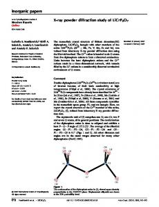
For the laboratory measurements, we used a horizontal goniometer in divergent BraggBrentano flat-plate geometry with both incident and diffracted Soller slits to minimize axial beam divergence, 2 mm divergent and 0.2 mm receiving slits. Cu Kq, radiation was scanned with a cooled germanium solid-state detector. Synchrotron-radiation measurements were performed on the X3B 1 beamline at the National Synchrotron Light Source (NSLS), Brookhaven National Laboratory. The triple-axis parallel geometry included Si channel- 111 -cut monochromator, flat specimen, Ge 111 -cut analyzer crystal, and proportional detector (Figure 1). Typical NIST SRM LaB, diffraction lineprofiles are presented in Figure 2. At this diEaction angle, synchrotron radiation gives four times smaller line width and 2.5 times larger peak-to-background ratio, despite twice as large a background count. Both line profiles are closely approximated with the Voigt function or its pseudo-Voigt and Pearson VII approximations.4 However, it is still a matter of debate5 why the line profiles tend to be almost pure Lorentz functions at high angles, the same effect that is observed for laboratory sources. Therefore, it is desirable to study the overall effect of geometrical aberrations on the difiaction-line shape.
ES I I f W. BEAM
Figure 1 Schematic view of X3Bl NSLS beamline in the (vertical) equatorial plane. monochromator crystal; ES: equatorial slit; S: specimen; A: analyzer crystal; D: detector.
Copyright (C) JCPDS-International Centre for Diffraction Data 1997
M:
250 - CuKq 220 ' 200 2
P/B = 71.5
150 100 50
-I m
,’
-3.3cps 1 0 _ 62.8 63.0 63.2 63.4
63.6 63.8
20 co> 1200) 1000 I
L
800 600
FWHM=
0.020"
400 200 -6.5cps -A 0 I I I I 1 I I I 1 I I 62.40 62.45 62.50 62.55 62.60 20 ("1 Figure 2 Diffraction-line
profiles of MST SRM LaE16obtained at laboratory and synchrotron (NSLS) x-ray sources. P/B denotes the peak-to-background ratio.
Copyright (C) JCPDS-International Centre for Diffraction Data 1997
SYNCHROTRON DIFFRACTION-LINE
SHAPE
The main equatorial instrumental factors affecting the diffraction-line profile and/or position are the following: (i) Source height (vertical angular distribution of the polychromatic beam) is approximated with the Gauss function at the bending magnet. It depends on the storage-ring electron (positron) relativistic factor y, the photon energy c, and the critical photon energy ec (5.04 keV at NSLS): gs(z) = exp(-41n2z2/FWHM~),
(1)
where the vertical (equatorial, for it is in the scattering plane) divergence is FWHM$
=
1.331
;
y =
[l - (v@-1’2
= E&z&2).
(2)
y( EC,/@u5 Here, v, E, and m, are the electron (positron) speed, energy, and rest mass, respectively, speed of light. (ii) Equatorial slit width 1 Izj I al2 &@
=
0
and c is the
Iz] > a/2
(iii) Normalized Darwin Bragg-reflection shape6 of the monochromator (rocking curve):
(3
and analyzer (perfect) crystals
gM,*(z) = s 2 / [z f (z” -s2)l’2]2
(4)
Here, s defines the region for a perfect reflection (without absorption) from a crystal. (iv) Specimen effects that cause important aberrations in laboratory divergent geometry, such as transparency, flat surface, and its missetting, are negligible in synchrotron parallel geometry with the analyzer crystal. The most important axial aberration is a divergence, which sometimes causes severe asymmetry at low angles. The effect on powder lime shapes was considered by van Laar and Yelon7 and recently applied to high-resolution synchrotron diffractometers by Finger, Cox, and Jephcoat.’ The total diiaction-line profile results from a convolution of all the contributions, which has to be accomplished numerically. However, for most purposes, a simple estimation of line widths as a fimction of diffraction angle may suffice. Wavelength dispersion follows from the Bragg law:
A/l//l = (w;l, + 0; + FWHM;)ln
cot8.
Here, the shape of perfect Bragg reflection is approximated with the Gauss function. % designate monochromator and analyzer-crystal Darwin widths. They depend on the structure polarization, absorption, and temperature (see for instance Warrer?). To recognize the relative importance of various contributions, we estimate the resolution at the X3B 1 NSLS beamline with 8 keV photon energy, that is, the approximate wavelength: Copyright (C) JCPDS-International Centre for Diffraction Data 1997
(5) and oA factor, angular Cu Ka
1.0
1.5
2.0
2.5
3.0
3.5
4.0
earson VII fits to the line profiles of LaB, and different broadening Figure3PwHMrofsplit-P models presented with lines.
FWHh$ ~(111
Si, 8 kev)
(2.5 GeV,S kev) = 0.0021’ ;
= 0.0190” ;
oA(l 11 Ge, 8 kev)
= 0.0045”.
(6)
It seems that the Darwin widths of both analyzer and monochromator crystals make a minor contribution and can be neglected in the first approximation. However, this large a divergence would yield very poor resolution (see Figure 3) and it must be controlled by the narrow equatorial slit in fi-ont of the specimen. The FWHM#yields the height of the beam at the slit position of about 4.5 mm for the X3Bl beamline (ring-slit distance is 13.7 m). Usually, at least three times narrower slit has to be used to improve the resolution. For instance, we collected the LaB, data at 1.30049(3) A with 0.75 mm equatorial-slit width (Figure 3). Line profiles were fitted with a split-Pearson VII function to model the peak asymmetry effects. The main peak-width contributions are now
o,(lll
Si, 9.54 kev)
@v = 0.0031”; = 0.0015” ; ~~(111 Ge, 9.54 kev)
Copyright (C) JCPDS-International Centre for Diffraction Data 1997
= 0.0032”.
(7)
0.75 mm equatohl slit
15000
10000 ti 3 5000
Figure 4 Voigt-functionfit (full line) to the 3 11 ILaB6profile (crosses). The difference pattern is given below.
Here, the vertical divergence & is defined by the equatorial slit. Certainly, the monochromator and analyzer Darwin widths become significant. To calculate the FWHM, we use the expression of Sabine:2 P
= &2tanBltanB,
+ 6.&(2tanO/tanO,
- tanO,ltanO, - tanB,ltanOJ2
- 1)2 + 0:
(8)
+ (Iv& + 4&(12I&). Here, we add the influence of specimen size (which approximately equals the equatorial-slit width IV& and receiving-slit width IV,, where DsR is the distance from specimen to receiving slit. This term can be neglected when the analyzer crystal is used. Note that the slit-width contribution to the variance Wis weighted by the factor l/12 (compare to Wilsong):
Copyright (C) JCPDS-International Centre for Diffraction Data 1997
0.15
I
I
I
O _
,o,
,
I
I
PL
,
,
,
1.3 it
,
(
,
(
I
,
I
s-
H
0.75 mmES
0.10
n
m g
0.05
2 tan0 1”“l”“l””
I
cuKq
‘I’/-
I
2 ,
c n
0.20
% ; 0.‘” IV
_
r -
tan0 Figure 5 Parameters of Voigt-function fits to LaB6 peaks using synchrotron (upper) and laboratory (bottom) source. Linear regression curves not fitted through the first two lines because of asymmetry. Copyright (C) JCPDS-International Centre for Diffraction Data 1997
0.10 -
o
1.3 A
0.2smmEs
0.08 -
c h
0.06 -
2 Q. 0.04 -
Figure 6 The parameters of Voigt-function fits to line profiles of LaB, using
narrower entrance slit. 7000
mm.,m.,
. . . mx. ,‘I
* m. b .m.
,.
1 m. . . .
843+922+850+762
figure
7 LaB, line profile recorded with the 1.5
Copyright (C) JCPDS-International Centre for Diffraction Data 1997
mm wide equatorial slit.
1l2wlD
(2e
v =