Abstractâ New possibilities for realization of narrow-band transmission filters are introduced. Guided-mode resonance ef- fects in thin-film multilayer structures ...
464
IEEE PHOTONICS TECHNOLOGY LETTERS, VOL. 9, NO. 4, APRIL 1997
Diffractive Narrow-Band Transmission Filters Based on Guided-Mode Resonance Effects in Thin-Film Multilayers S. Tibuleac, Student Member, IEEE, and R. Magnusson, Senior Member, IEEE
Abstract— New possibilities for realization of narrow-band transmission filters are introduced. Guided-mode resonance effects in thin-film multilayer structures incorporating a grating layer are shown to yield high-efficiency bandpass transmission filters. Calculated transmission characteristics for such filters are presented and contrasted with characteristics of corresponding thin-film interference filters. Index Terms—Bandpass filters, guided-mode resonances, optical diffraction, optical filters, thin films, waveguide gratings.
N
EW TYPES OF optical transmission filters with unique characteristics can be realized utilizing high-spatialfrequency gratings integrated with homogeneous thin-film layers. The grating induces guided-mode resonance effects that yield narrow-line transmission peaks superimposed on the transmission spectrum of the equivalent thin-film system. The first report of these effects emphasized filters with two gratings, one on each side of the thin-film stack [1]. In this letter, simpler architectures are introduced to facilitate practical exploitation of these fundamental effects. In particular, it is shown that highly efficient transmission filters can be realized with a single grating embedded in the thin-film stack. For materials with suitably high-dielectric constants, furthermore, it is shown that good transmission filter characteristics may be obtained with a single surface-relief grating element. The characteristics of these new filters are compared and contrasted with classical band-pass interference filters of the Fabry–Perot variety. Theoretical work has shown that guided-mode resonance effects in diffractive thin-film structures yield optical reflection filters with 100% efficiency, symmetrical lineshapes, near-zero nonoscillatory sidebands over extended wavelength regions, narrow (or wide) controllable linewidths, and other favorable attributes [2]. Single- and multilayer reflection filters with near ideal features have been theoretically demonstrated by utilizing antireflection design to suppress reflections adjacent to the resonance peak [3]. Numerous applications have been identified [4]. Experimental results verifying the theoretically predicted high-resonance efficiencies for reflection filters have been reported in the optical spectral region [5], [6], in the
Manuscript received September 27, 1996; revised December 13, 1996. This work was supported in part by the Texas Technology Development and Transfer Program under Grant 003656-140 and by Texas Instruments, Inc. The authors are with the Department of Electrical Engineering, The University of Texas at Arlington, Arlington, TX 76019 USA. Publisher Item Identifier S 1041-1135(97)02438-5.
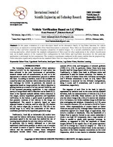
(a)
(b) Fig. 1. Thin-film multilayer model incorporating a single grating in two example configurations: (a) with the grating in the center layer, and (b) with the grating in the top layer of the structure. R is the system reflectance and T is its transmittance. The dielectric constants, ", in the various regions, layer thicknesses, d, and grating period, 3, are indicated.
millimeter wave region [7], and in the microwave region [8]. The transmission filters of chief interest in this letter have not yet been experimentally demonstrated. The current state of this field of research was summarized at a recent conference [9]. Fig. 1 illustrates the dielectric thin-film multilayer system under study in which a grating with a square-wave profile replaces one of the homogeneous layers, for example, the center layer as in the structure of Fig. 1(a), or the first layer as in the surface-relief device shown in Fig. 1(b). The gratings have sufficiently high-spatial frequency such that a zerothorder diffraction regime prevails over the wavelength bands of interest with all higher order diffracted waves being cut off. The normally incident electromagnetic plane wave is assumed to possess TE polarization with the electric-field vector orthogonal to the plane of the figure for the example
1041–1135/97$10.00 1997 IEEE
TIBULEAC AND MAGNUSSON: DIFFRACTIVE NARROW-BAND TRANSMISSION FILTERS
465
Fig. 2. Transmittance of a nine-layer structure with a grating in the fifth layer. All layers are quarter-wave thick at 500 nm. The grating parameters are 3 = 300 nm, "H;5 = 2.52 , "L;5 = 2.22 , d5 = 53.1 nm. The odd homogeneous-layer parameters are " = 2.352 and d = 53.2 nm with the even-layer parameters being " = 1.382 and d = 90.6 nm. The dielectric constant for the cover region is "c = 1 and that of the substrate is "s = 1.522 .
Fig. 4. Transmittance of a nine-layer Fabry–Perot filter. The fifth (center) layer is half-wave thick with all others being quarter-wave thick at 500 nm. The central layer has "5 = 2.352 and d5 = 106.1 nm. For the other odd layers " = 2.352 and d = 53.2 nm whereas " = 1.382 and d = 90.6 nm for the even layers. The dielectric constant for the cover region is "c = 1 and that of the substrate is "s = 1.522 .
Fig. 3. Broad-band response of the system defined in Fig. 2.
Fig. 5. Transmission response of the system defined in Fig. 4 with the central homogeneous layer of the Fabry–Perot filter replaced by a grating with 3 = 300 nm, "H;5 = 2.52 , and "L;5 = 2.22 .
results presented. The numerical results are obtained using rigorous coupled-wave analysis [10]. Fig. 2 illustrates the transmission characteristics of a ninelayer guided-mode resonance filter made with a single grating in the central (fifth) layer. All layer thicknesses are selected to be quarter wave at 500-nm wavelength. A highly efficient (almost 100%) narrow-line transmission filter with linewidth (FWHM) of 0.11 nm and low sidebands over a range of approximately 60 nm is obtained. Since this multilayer waveguide-grating structure supports several guided modes, multiple resonance peaks are observed as indicated in Fig. 3 that gives the transmission response of the same system over a wider wavelength region. It is seen in Fig. 3 that the filter peak of Fig. 2 corresponds to the TE guided mode with the fundamental mode occurring at the long-wave end of the spectrum. For comparison, Fig. 4 shows the transmittance response of a nine-layer thin-film (i.e., no grating) interference filter made with the same materials. The central layer (layer 5) has a half-wave thickness whereas the others are quarter-wave
thick. Converting the central layer to a half-wave grating layer results in the response shown in Fig. 5. The guided-mode resonance spectrum occurs superimposed on the classical one. Similarly, if the grating in the quarter-wave system of Fig. 3 is replaced by a homogeneous layer with the same average dielectric constant and thickness, the background homogeneous thin-film response remains which is essentially that in Fig. 3 with the resonance peaks removed. The linewidth of the guided-mode resonance of Fig. 2 is significantly smaller than the linewidth of the Fabry–Perot peak while maintaining comparable transmittance values at the central wavelength. A Fabry–Perot bandpass filter with 27 layers obtains the narrow linewidths of the nine-layer waveguide-grating filter with the response of Fig. 2 if the same materials are employed in both structures; [11] addresses comparisons of these two filter types in more detail. The linewidths of the waveguide-grating resonance filters can be controlled by appropriately selecting the dielectric constants of the structure to vary the modulation of the grating and the confinement of the waveguide modes [4].
466
IEEE PHOTONICS TECHNOLOGY LETTERS, VOL. 9, NO. 4, APRIL 1997
the grating layer. This enhances the leakage of the waveguide grating resulting in high transmittance at the resonance wavelengths. The situation is comparable to the Fabry–Perot filter with dielectric mirrors on both sides of the etalon layer. In conclusion, calculated examples illustrating the properties of diffractive narrow-band transmission filters based on guided-mode resonance effects in thin-film multilayers have been presented. These effects open up new possibilities for design and applications of thin-film optical elements and devices. REFERENCES
Fig. 6. IR spectral response of a five-layer filter with a surface-relief grating in the first layer. The grating parameters are 3 = 4.14 �m, "H;1 = 4.2432 (Ge), "L;1 = 1 (air), and d1 = 2.0 �m. The odd homogeneous-layer parameters are " = 4.2432 and d = 0.623 �m with the even-layer parameters being " = 2.202 (ZnS) and d = 1.20 �m. Both cover and substrate are taken to have " = 1.
As a final example, Fig. 6 shows a guided-mode resonance transmission filter response in the IR spectral region. The transmission peaks at efficiency exceeding 90% close to the CO laser wavelength of 10.6 m. Due to the larger dielectric constants available in the IR region, allowing larger grating modulation and increased off-resonance reflectance, this filter is implemented with only five layers with the grating placed in the first layer as a surface-relief element. The placement of the grating within the multilayer system is of key importance for efficient transmission filter design. Essentially, the electromagnetic field distribution must have a sufficiently strong overlap and interaction with the diffractive element. To obtain the filter response shown in Figs. 2 and 3 (i.e., high-filter transmittance at the desired wavelength and low transmittance outside the filter passband), the grating is surrounded by high-reflectance layers enhancing the field in
[1] R. Magnusson and S. S. Wang, “Transmission bandpass guided-mode resonance filters,” Appl. Opt., vol. 34, pp. 8106–8109, Dec. 1995. [2] S. S. Wang and R. Magnusson, “Design of waveguide-grating filters with symmetrical line shapes and low sidebands,” Opt. Lett., vol. 19, pp. 919–921, June 1994. , “Multilayer waveguide-grating filters,” Appl. Opt., vol. 34, pp. [3] 2414–2420, May 1995. , “Theory and applications of guided-mode resonance filters,” [4] Appl. Opt., vol. 32, pp. 2606–2613, May 1993. [5] M. T. Gale, K. Knop, and R. H. Morf, “Zero-order diffractive microstructures for security applications,” in Optical Security and Anticounterfeiting Systems, Proc. Soc. Photo-Optical Instrumentation Engineers, W. F. Fagan, Ed., vol. 1210, Jan. 1990, pp. 83–89. [6] S. Peng and G. M. Morris, “Sub-nanometer linewidth resonant grating filters,” in Proc. Top. Meet. Diffractive Optics and Micro-optics, Boston, MA, vol. 5, 1996, pp. 257–260. [7] V. V. Meriakri, I. P. Nikitin, and M. P. Parkhomenko, “Frequency characteristics of metal-dielectric gratings,” Radiotekhnika i elektronica, vol. 4, pp. 604–611, 1992. [8] R. Magnusson, S. S. Wang, T. D. Black, and A. Sohn, “Resonance properties of dielectric waveguide gratings: theory and experiments at 4–18 GHz,” IEEE Trans. Antennas. Propagat., vol. 42, pp. 567–569, Apr. 1994. [9] R. Magnusson, S. Tibuleac, Z. Liu, D. Shin, P. P. Young, and S. S. Wang, “Thin-film filters with diffractive and waveguiding layers,” in Proc. Top. Meet. Diffractive Optics and Micro-optics, Boston, MA, vol. 5, 1996, pp. 246–248. [10] T. K. Gaylord and M. G. Moharam, “Analysis and applications of optical diffraction by gratings,” Proc. IEEE, vol. 73, pp. 894–937, May 1985. [11] S. Tibuleac and R. Magnusson, “Reflection and transmission guidedmode resonance filters,” to be published in feature issue on diffractive optics, J. Opt. Soc. Amer. A, July 1997, to be published.