DIGITAL SELF-TUNING TECHNIQUE FOR CONTINUOUS-TIME FILTERS G. Zatorre Navarro+, E. Peralías ‡, S. Celma Pueyo+, C. Aldea Chagoyen+, N. Medrano Marqués+ +
Electronic Design Group. University of Zaragoza, Spain. {gzatorre, scelma, caldea, nmedrano}@unizar.es ‡ Instituto de Microelectrónica de Sevilla (IMSE), Spain.
[email protected] ABSTRACT
In this paper a new auto-tuning digital technique is reported for continuous-time filters over VHF applications, based on phase detector. By using a 0.35 μm digital CMOS process, changes in frequency response of a 3thr-order low pass filter can be tuned with a 3.1% error over the designed value. This technique confirms the feasibility of the proposed scheme in continuous–time filter applications. The system consumes less area, power and tuning time than other proposed schemes. Simulated results show the building viability in a 10 MHz low pass filter. 1. INTRODUCTION The continuous-time technique has been used to implement filters where high frequency at low cost of silicon and power is required, instead of the switchedcapacitor or switched-current approaches [1]-[3]. The low cost CMOS technology is a good choice if the requirement of accuracy is relaxed and is the most economical solution if the whole system is implemented in a pure digital process. Among high speed processing signal applications, it is widely used in the IF band pass sections of RF front-end circuits and in the hard disk drive industry. These applications demand continuoustime filters with variable bandwidths over a wide range [4]. A possible solution could be to use discrete tuning for IF filters, in the same way that this technique is being used in other high frequency applications, such as IFbaseband strips [5] or read-channel filters [6]. On the other hand, we must not overlook the problems encountered on the analogue part in the current digital CMOS processes associated with the scaling down and low-voltage operation. Among these, the reduced dynamic range is of concern, making difficult conventional continuous tuning, used to compensate technological and temperature spreads, which degrades the dynamic range. So, it is necessary to provide an onchip automatic tuning scheme to achieve an accurate filter performance [7]-[8]. This circuit tunes the characteristic filter frequency in order to compensate fabrication tolerances, temperature variations and ageing. We can take advantage of the simplicity of the digital control algorithms to adjust the tuneable analogue part by
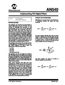
the digital algorithm thus yielding a considerable saving of area and power. In this paper, an innovative frequency digital auto-tuning algorithm is presented for use in integrated continuoustime filters which is simpler than other schemes [9]-[10] and which needs less silicon and power. 4-bit digitally auto-tuned third order low-pass filter was simulated using this technique yielding a 10 MHz fixed cut-off frequency low-pass filter with an error below 3% and tuning time lower than 1.6 µs. Simulation results and Monte Carlo analysis show the implementation viability and are presented in this communication. In section 2, a description of the overall system and its basic component blocks description are presented. Section 3 presents the proposed phase detector deep viability study with simulation results and Monte Carlo analysis. Conclusions are given in section 4. 2. SYSTEM DESCRIPTION 2.1. Auto-Tuning Scheme The whole system is made up of four blocks: an analogue filter with digitally tuneable characteristic frequency, a delayer stage, a phase detector and an up/down counter. The global system arrangement is depicted in Figure 1. A high accuracy reference harmonic signal Vref at desired filter characteristic frequency is fed into the system. This signal goes through the digitally tuneable analogue filter, yielding signal A, and into the delayer block, yielding signal B. At filter output, the signal suffers a known delay which depends on the filter type and its characteristic frequency. The delayer block must provide the same delay as the filter caused by the filter over the reference signal when working at the desired characteristic filter zc[0:3] Q0
Q1
Q2
Q3
Q0 Programmable Filter Vref
Q1
Q2
Q3
Cd
A
Cu
B Phase Detector
Up/Down Counter Reset
Delayer
Figure 1. Overall system description.
Enable
20
zc[0:3] = 15
3.8 2.3 0.8 -0.8 -2.5
0
-4.2
2.2. Phase Detector Block zc[0:3] = 0
-20 7
8
9
10
Freq (MHz)
11
12
13
Figure 2. AHDL-described tunable filter delay response.
frequency. Only when the filter is not working at the desired characteristic frequency is there a lag between the filter and delayer outputs (A and B). The filter and delayer outputs are led into the phase detector in order to compare their relative phases. This block generates one pulse per cycle in the Cd (down) output, if the filter output signal goes ahead, and one pulse per cycle in the Cu (up) output when the filter signal is delayed. In this way, Cu and Cd signals control the up/down counter, the state of which is used to control the digitally tuneable analogue filter. When parameters such as programmability range, phase detector resolution and up/down counter bits are properly selected, the system stabilizes at the state with the filter tuneable characteristic frequency closest to the reference signal frequency. The 4-bit digitally tuneable characteristic frequency filter was described using AHDL and reproduces the behaviour of a third order low pass filter. Figure 2 shows the delay with regard to the lag caused by the filter working at the desired characteristic frequency, for each zc[0:3] value. As can be observed, the filter characteristic frequency can be linearly adjusted from 7 MHz to 13 MHz using the controlling 4-bit digital word. A 10 MHz characteristic frequency filter was selected in order to prove the technique viability. The delayer block can be implemented in several ways depending on the filter phase response. To show the proposed system functionality a VERILOGA-described delayer cell was used in this work. A standard up/down binary counter with reset, enable and
2.3. Phase Detector Operation Principle The phase detector must provide a pulse per cycle in Cd and no change in Cu if A is ahead, and if B is ahead, a pulse per cycle in Cu and no pulse in Cd. To prevent undesired pulses, AC to Cd delay (CPD) and BC to Cu 1
0 1
Rst
Reset Path
The signals to be compared, A and B, are driven through VERILOGA-described identical comparators to provide digital square shape signals to the next stages, AC and BC as shown in Figure 3. These two conditioned signals are connected to the clock inputs of identical D-type flip-flops through a buffer. At the same time each of the conditioned signals is connected to each one of a NAND gate input whose output is attached to both of the flip-flop reset inputs (see Figure 3). The flip-flop D inputs are fixed to 1. This topology ensures that only one or none of the flip-flops loads the D input per cycle, if the Rst signal arrives faster than the ClkA and ClkB signals to the flip-flops; that means the “Clock Path Delay” has to be shorter than the “Reset Path Delay” (CPD and RPD respectively in Figure 4). These path delays ensure that the reset signal resets the flip-flips faster than the clock signal changes the flipflop state. These delays also set the resolution of the system matching the filter output signal phase with the delayer output signal phase as can be seen in the next section. This issue makes the phase detector the most delicate block as it requires precise clock path delay stages between AC and BC and flip-flop clocks and resets.
Cd
-10
CPD
Clock Path 1 AC
Q Cd
D
D-Type Latch ClkA C
Comparator
RD
ABD
RPD
0 1
Ac
Rst
ND
0 1
Bc
Delay (ns)
10
separate up/down clocks was used with minimal changes; a control which prevents 0 to 2n-1 and 2n-1 to 0 transitions was implemented. On the other hand, the more significant bit was stored in T flip-flops with reset control, while the rest of the bits where stored using T flip-flops with set control. In this way the system starts to count from 2n-1-1=7 (that is, starting cut-off frequency at 9.8 MHz) after a reset signal instead of starting from 0 or 2n-1.
BC
Comparator
ClkB 1
C D-Type Latch D Q Cu
0 0.299
Figure 3. Phase detector.
0.300
0.301
0.302
0.303
0.304
Time (us)
0.305
Figure 4. Delay diagrams.
0.306
0.307
0.308
7.0
7.0
13 7-
M
Hz
3.8
delay at wb+2
3.04
delay at wa+2
2.3
ABD (ns)
delay at wb+1
1.56
delay at wa+1
0.79
delay at wb
0
0.00
delay at wa
-0.8
delay at wb-1
-1.62
delay at wa-1
-2.5
delay at wb-1
8 6.
2 -1
.8
M
-3.30
Hz
-7.0
-7.0 4
6
8
Word
10
12
Figure 5. ABD for every digital word for two different AHDL described filters centred at 10 MHz and 9.8 MHz.
delay (same delay) must be longer than the delay via reset (BC to Cd/Cu if AC arrives first at the NAND gate). Furthermore, the system must not discriminate A to B lags shorter than a certain quantity if we want the system to stabilize at the best possible digital word. Imagine A is ahead of B and let’s call this lag ABD (see Figure 4). The AC rise forces the flip-flop to load D value, which is fixed at 1, after CPD. This produces a rise in the Cd signal and the up/down counter counts down 1 (see Figure 3 and 4). When the BC rise occurs, it changes the NAND gate state causing activation of the flip-flop reset and the Cd signal to drop after ND + RD. The pulse width generated in Cd is equal to ABD – CPD + (ND + RD). The latter parenthesis is the “Reset Path Delay”, RPD as can be seen in Figure 3 and 4. When ABD < CPD – RPD there is no pulse in Cd. As the lag from the Bc rise up to Cu rise is CPD too, the Cu state does not change and there is no pulse in Cd nor Cu. The phase Detector operation principle is based on achieves an accurate delay difference between the CPD lag and RPD lag. Because of the symmetry of the system with regard to the AC and BC signals the same occurs if BC is ahead. 2.4. Timing Calculation
word. The more restrictive case is when the desired frequency matches a digital word exactly, like wb in Figure 5 (where the representation of ABD versus the tuning digital word are depicted for tow AHDL described filters). In this situation RDCR must be shorter than the shortest between at wb-1 and at wb+1 delay. In Figure 5 this condition is satisfied if RDCR < 1.56 ns. On the other hand, the system must stabilize at the desired state, to ensure this situation the phase detector has not to notice delays shorter than the delay achieved at this state. In this case the worst situation is when the desired frequency matches exactly in the middle between two consecutive digital words, wa and wa+1, as depicted in Figure 5. RDCR must be longer than the longest ABD at these digital words. From Figure 5 we see this is satisfied if RDCR > 0.8 ns. We can see the phase detector has not to generate any output pulse if ABD is shorter than 0.79 ns and must generate a pulse if the lag is greater than 1.59 ns, in this case RDCR must satisfy: 0.79 ns < RDCR < 1.56 ns to ensure that the system stabilizes at the best digital word. 3. PHASE DETECTOR VIABILITY STUDY: SIMULATION RESULTS As shows in Section II, the phase detector requires precise relative delay path implementation between reset and clock paths, RDCR (see Figure 3). Theoretically, this lag has to be fixed between 0.8 ns and 1.5 ns. Evidently, the best choice is 1.2 ns but this lag could change due to mismatching, ageing, temperature changes and working conditions. To ensure the viability of the system several simulations were carried out. In Figure 3 each element was substituted by AMS c35b3 process library elements. For each element type, the smaller was used. The buffers were changed for 7 library buffers (BUF2) in serial arrangement, this configuration provides a clock path delay (CPD) of approximately 1.35 ns using library flipflops (DFC1). The NAND gate was NAND20 and provides a reset path delay (RPD) of 0.36 ns. Simulation results show this arrangement can detect delays between 1.5 1.0 0.5 0.0
As shown in section 2.3, a pulse is generated if the lag between A and B (ABD) is bigger than CPD – RPD; we shall name this latter quantity “relative delay between clock path and reset path”: RDCR. The phase detector does not react for shorter values of ABD than RDCR, this quantity fixes system accuracy matching tuned characteristic frequency with desired characteristic frequency. This lag must be calculated according to the desired characteristic frequency, tuning bit number and characteristic frequency filter integration accuracy. Two timing restrictions must be achieved. Firstly, the system must reach the best possible digital word and secondly it must stabilize at this word without generating any pulse at either the Cu or the Cd outputs. To achieve the first aim, the phase detector must perceive any delay longer than the ABD at this digital
-0.5 -1.0
ABD at estable estate (ns)
-1.5 4
Achieved cut-off frequency error (%)
2 0 -2 -4 15 12 9 6 3 0 6.8
zc[0:3] value at estable estate
7.8
8.8
9.8
10.8
At zc[0:3]=7 cut-off frequency (MHz)
11.8
12.8
Figure 6. Final ABD, cut-off frequency error and zc[0:3] value after tuning process versus AHDL-described filter at zc[0:3]=7 cut-off frequency.
1.20
Delays vs Temp (Vdd = 3.3 V, N = 98)
RDCR (ns)
1.16
1.8
1.12 1.08
Delays vs Vdd (T = 27 ºC, N = 100)
RDCR (ns) Min =0.73 Max=1.13 M =0.95 S.D =9.0 %
Min = 0.79 Max= 1.24 M = 1.03 S.D =10.0 %
RDCR (ns) Min = 0.85 Max= 1.34 M = 1.11 S.D =11.0 %
Min = 0.90 Max= 1.45 M = 1.19 S.D =12.2 %
1.4
1.04
1.8 1.4
0.999 ns
1.00
1.0
0.96 0.40
0.6 0 ºC
0.383 ns
0.36
0.55
0.32
0.50
0.28 Delay Bc-nQA (ns)
0.24 1.43
Delay Ac-nQA (ns)
1.42
27 ºC
54 ºC
80 ºC
Min = 1.18 Max = 1.98 M = 1.58 S.D = 16.5 %
Min = 1.09 Max = 1.79 M = 1.44 S.D = 14.7 %
Min = 1.016 Max = 1.65 M = 1.33 S.D = 13.5 %
2,97V
3,30 V
3,63 V
CPD (ns)
CPD (ns)
1.0 0.6 0.55 0.50
0.45
0.45
0.40
0.40
0.35
0.35
0.30
0.30
0.25 1.41
0.25 0 ºC
27 ºC
54 ºC
80 ºC
2,97 V
3,30 V
3,63 V
1.40
2.0
1.39
1.8
1.8
1.6
1.6
1.4
1.4
1.2
1.2
1.382 ns
1.38 1.2
1.4
1.6
ABD (ns)
1.8
2.0
Figure 7. Delay study versus ABD lag.
Ac and Bc (ABD) longer than 1.225 ns. Due to the building process, ageing and temperature changes, tuneable filter starting cut-off frequency (frequency at zc[0:3] = 7) can be from 6.86 MHz to 12.74 MHz (if it is designed to be 9.8 MHz and considering the mentioned 30% error). Figure 6 represents tuneable filter parameters after the tuning process for 100 AHDLdescribed tuneable filters with, at zc[0:3]=7 from 6.8 MHz to 12.8 MHz, represented in the x-axis. As can be seen the error is lower than 3.1 %. The maximum tuning time was only 1.6 µs. In Figure 7 RPD, CPD and RDCR dependences with ABD are presented. As can be seen, this dependence is appreciable only when the relative (Ac, Bc) lag is shorter than 1.3 ns. At working frequencies this issue does not limit the tuning range (at any ABD value, RDCR < 1.20 ns) but to reach higher characteristic frequency filters, the implementation must be done using faster technologies with a shorter channel length. Figure 8 depicts phase detector Monte Carlo analysis results. This analysis was carried out without correlation definition for any element. Analysis results predict a RDCR compatible with the calculated values, this means the building process will not significantly affect the phase detector resolution if a careful layout is developed. 4. CONCLUSIONS A new auto-tuning methodology is presented in this paper. Working principle is based on a phase detector with accurate relative path delays implementation. Preliminary studies show the phase detector building viability. The tuning scheme was simulated on an AHDL code for a Butterworth third-order low-pass filter yielding a 10 MHz cut-off frequency filter with an error lower than 3.1 % and a tuning time of 1.6µs. 5. REFERENCES
RPD (ns)
RPD (ns)
1.0
2.0
1.0 0 ºC
27 ºC
54 ºC
80 ºC
2,97 V
3,30 V
3,63 V
Figure 8. Critical phase detector delays box and whisker plots versus temperature and bias voltage (Vdd). ABD = 2ns. [1] P.E. Allen and E. Sánchez-Sinencio, Switched Capacitor Circuits, Van Nostrand Reinhold, New York, 1984. [2] C. Toumazou, J. B. Hughes and N. C. Battersby, SwitchedCurrents and Analogue Technique for Digital Technology, Peter Peregrinus Ltd, 1993. [3] R. Schaumann, “Continuous-time integrated filters-A tutorial”, IEEE Proceedigns, vol. 136, no. 4, pp. 184-190, 1989. [4] R. Castello, I. Bietti and F. Svelto, “High-frequency analog filters in deep-submicron CMOS technology” in Proc. IEEE ISSCC'99, 1999, paper MP 4.5, pp. 75-75. [5] P. Orsatti, F. Piazza and Q. Huang, “A 71-MHz CMOS IFBaseband Strip for GSM”, IEEE J. Solid-State Circuits, vol. 35, no. 1, pp. 104-108, 2000. [6] G. Bollati, S. Marchese, M. Demicheli and R. Castello, “An Eighth-Order CMOS Low-Pass Filter with 30-120 MHz Tuning Range and Programmable Boost”, IEEE J. SolidState Circuits, vol. 36, no. 7, pp. 1056-1066, 2001. [7] R. Schaumann and M. E. Van Valkenburg, Design of Analog Filters, Oxford University Press, New York, 2001. [8] Y. P. Tsividis and J. O. Voorman, Integrated ContinuousTime Filters. Principles, Design and Applications, IEEE Press, New York, 1993. [9] H. Huang and E. K. F. Lee, “Design of Low-Voltage CMOS Continuous-Time Filter with On-Chip Automatic Tuning,” IEEE Journal of Solid-State Circuits, vol. 36, pp.1168-1177, August 2001. [10] A. A. Emira, E. Sánchez-Sinencio, “A Pseudo Differential Complex Filter for Bluetooth With Frequency Tuning,” IEEE Transactions on Circuits and Systems-II: Analog and Digital Signal Processing, vol. 50, no. 10, pp. 742-754, October 2003.