Accepted Manuscript Efficient Variable Bandwidth Filters For Digital Hearing Aid Using Farrow Structure Nisha Haridas, Elizabeth Elias PII: DOI: Reference:
S2090-1232(15)00059-4 http://dx.doi.org/10.1016/j.jare.2015.06.002 JARE 402
To appear in:
Journal of Advanced Research
Received Date: Revised Date: Accepted Date:
31 March 2015 2 June 2015 8 June 2015
Please cite this article as: Haridas, N., Elias, E., Efficient Variable Bandwidth Filters For Digital Hearing Aid Using Farrow Structure, Journal of Advanced Research (2015), doi: http://dx.doi.org/10.1016/j.jare.2015.06.002
This is a PDF file of an unedited manuscript that has been accepted for publication. As a service to our customers we are providing this early version of the manuscript. The manuscript will undergo copyediting, typesetting, and review of the resulting proof before it is published in its final form. Please note that during the production process errors may be discovered which could affect the content, and all legal disclaimers that apply to the journal pertain.
1
2
3
Efficient Variable Bandwidth Filters For Digital Hearing Aid Using Farrow Structure Nisha Haridas∗ and Elizabeth Elias
5
Department of ECE, National Institute of Technology Calicut, India Email: ∗
[email protected] Tel: +919895465581
6
Efficient VBW Filters For Digital Hearing Aid Using Farrow Structure
4
1
7
Abstract
8
Design of a digital hearing aid requires a set of filters that gives reasonable audio-
9
gram matching for the concerned type of hearing loss. This paper proposes the use
10
of a variable bandwidth filter, using Farrow subfilters, for this purpose. The de-
11
sign of the variable bandwidth filter is carried out for a set of selected bandwidths.
12
Each of these bands is frequency shifted and provided with sufficient magnitude
13
gain, such that, the different bands combine to give a frequency response that
14
closely matches the audiogram. Due to the adjustable bandedges in the basic fil-
15
ter, this technique allows the designer to add reconfigurability to the system. This
16
technique is simple and efficient when compared with existing methods. Results
17
show that lower order filters and better audiogram matching with lesser matching
18
errors are obtained using Farrow structure. This, in turn reduces implementation
19
complexity. The cost effectiveness of this technique also comes from the fact that,
20
the user can reprogram the same device, once his hearing loss pattern is found to
21
have changed in due course of time, without the need to replace it completely.
22
Keywords: Farrow structure; variable bandwidth filter; Audiogram
2
23
Introduction
24
Hearing loss patterns differ according to the anatomical and sensorineural dif-
25
ferences. For example, Presbyacusis is an age related hearing loss. It usually
26
affects the high frequencies more than the low frequencies [1]. The softest sound
27
that can be recognized in the frequency range 250 Hz to 8000 Hz is represented
28
in an audiogram. Any sound that is heard at 20 dB or quieter are considered to be
29
within the normal range [2]. For the patients with hearing losses, certain kinds of
30
hearing aids are required to improve the quality of hearing. An important unit of
31
a digital hearing aid consists of the digital filters that can tune the amplitudes se-
32
lectively to a person’s particular pattern of hearing loss. In case of Presbyacusis,
33
simple amplification merely makes the garbled speech, sound louder [2]. They
34
usually need a hearing aid that selectively amplifies the high frequencies. Thus,
35
the filtering unit should be able to provide gain selectively to different frequency
36
bands. This allows the filter response of the hearing aid to have minimum match-
37
ing error response relative to the audiogram, within a tolerance limit. 3 dB can be
38
taken as the limit, as most people are not sensitive to lower errors [3].
39
A good amount of flexibility, minimum hardware, low power consumption,
40
low delay and linear phase (to prevent distortion) are the required characteris-
41
tics of any digital hearing aid. Significant amount of study is available on the
42
bank of filters designed for audiogram matching. Initial approaches were based
43
on uniform subbands. Since, humans perceive loudness on a logarithmic scale,
44
non-uniform filter banks are better suited, so that the matching can be achieved
45
with lesser number of sub-bands, if possible. Some of the methods used to gen-
46
erate non-uniform subbands for digital hearing aid application, as found in the
47
literature, are as follows. 3
48
A frequency response masking technique using two prototype filters [4], is
49
employed to generate an 8-band non-uniform FIR digital filter bank. Matching
50
errors are reported to be better compared to 8-band uniform filter bank and the
51
number of multiplications are lower since half-band filters are used. However, the
52
delay introduced is large and delays more than 20ms may hamper with lip-reading
53
[5]. This problem was addressed by using a similar method, but with three pro-
54
totype filters and 16 bands by Wei et al., [5]. Still, for lower matching errors,
55
better precision in designing the filters and their cascade and parallel placements,
56
are to be taken care of, which would increase the design cost. An approach using
57
variable filter-bank (VFB) that consists of three channels having separately tun-
58
able gains and band edges, is considered by Deng [3]. The method has increased
59
flexibility, but the use of infinite impulse response (IIR) digital filters introduces
60
overall non-linear phase to the system. Wei et al., [6] gives a flexible and com-
61
putationally efficient digital finite impulse response (FIR) filter bank based on
62
frequency response masking (FRM) and coefficient decimation. The frequency
63
range is divided into three sections and each section has three alternative subband
64
distribution schemes. The decision on selecting the sections for each sub-band for
65
the selected audiogram has to be made wisely and the flexibility of the system is
66
limited by this selection.
67
A change in the design methodology can be found in the approach by James
68
et al., [1], where, a variable bandwidth filter using sampling rate conversion tech-
69
nique, is used for the digital hearing aid application. The filter order or filter coeffi-
70
cients need not be altered to obtain the variability in the bandwidth. A fixed length
71
FIR filter is designed initially, whose characteristic bandwidth is then changed by
72
modifying the bandwidth ratio, given as input to an interpolation filter. Using this
4
73
filter structure and by varying the bandwidth ratio, a bank of filters that processes
74
different subbands, is realised. However, the hardware complexity of the structure
75
is seen to be high.
76
This paper proposes the design of a bank of digital filters that can provide
77
reasonably good matching with the set of audiograms considered. A variable
78
bandwidth (VBW) filter, whose bandwidth can be varied dynamically, is imple-
79
mented using Farrow structure. All the required bandwidths for the set of selected
80
audiograms are derived from the VBW filter. These filters are then tuned sep-
81
arately to the optimum center frequencies and bandwidths to match each of the
82
audiogram. Thus, once the VBW filter is designed using the proposed technique,
83
the instrument can be tuned by the manufacturer to individual user audiogram
84
characteristics. This results in an efficient method to realize reconfigurable digital
85
hearing aid. A primitive form of this work is done by us for a single audiogram
86
and is published in a conference proceeding [7].
87
An adjustable hearing aid helps the user to adjust the device according to the
88
change in hearing loss pattern with time or age. Yet another advantage is that
89
the vendors of hearing aid can design an instrument to suit a set of hearing loss
90
patterns. Here, it can be customized for any of its users, using a small set of tuning
91
parameters. The proposed method aims to design a reconfigurable filter structure
92
to suit a set of hearing loss pattern. Consequently, the cost of the instrument can
93
be lowered without compromising on the quality.
94
Section 2 explains how Farrow based variable bandwidth filters can be used in
95
digital hearing aid. In Section 3, the efficiency of the method is verified on a set
96
of audiograms by comparing with an existing method. The method is also applied
97
to audiograms of real patients in the same section. Section 4 concludes the paper.
5
98
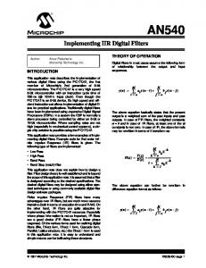
Preliminaries - Farrow Structure
99
The design of the subbands in the digital hearing aid scenario given in this
100
paper, is based on a variable bandwidth filter. There are many ways in which
101
filters with adjustable bandedges are approached in the literature [8].
102
We propose the Farrow structure implementation for the set of variable band-
103
width filters used in the digital hearing aid. In the Farrow structure, the overall
104
response is derived as a weighted linear combination of fixed subfilters as shown
105
in Fig.1 [9]. The weights control the tunable bandwidths.
106
The Farrow structure was initially derived as a digital delay element, where
107
the desired impulse response is approximated using (L + 1)th - order polynomials
108
of a delay parameter, d, [10]. Later, modified Farrow structure was proposed by
109
Johansson et al., [9], where the subfilters are designed to have linear phase (sym-
110
metric coefficients), which also reduces the overall implementation complexity.
111
Farrow structure is an efficient way to realize tunable filter characteristics such as
112
variable fractional delay [9, 11, 12], sampling rate conversion (SRC) [13, 14] and
113
variable cut-off frequencies [15]. In a variable fractional delay filter, all the input
114
samples are delayed by a factor, whereas in SRC, every input sample is delayed
115
by varying factors.
116
An ideal frequency response of an FIR filter, Aideal (e jω ) of order N can be writ-
117
ten such that the magnitude and phase responses are expressed with polynomial
118
coefficients of ω as given by Luo et al. [16], N ∑ ∑M m Aideal (e jω ) = ( an ωn )e− j[(N/2)ω+ m=1 bm ω )
(1)
n−0
119
where M is the order of phase response and 6
∑M
m=1
bm ωm is the fractional delay,
120
d, in a Farrow structured fractional delay filter. This can be rewritten with unity
121
magnitude as, Aideal (e jω ) = e− j[(N/2)ω+
∑M
m=1 bm ω
m)
(2)
122
The frequency response can be controlled by adjusting the polynomial coefficient
123
bm . Each polynomial phase component can be approximated [16] using Taylor
124
series of ω, with an error ϵ,
e
− jbm ωm
=
P ∑ (− jbm ωm ) p
p!
p=0
(3)
+ϵ
125
where P is the order of Taylor series for each polynomial phase component and
126
the the Taylor approximation error ϵ. Thus, the approximated frequency response
127
for the fractional delay filter is, jω
Aapprox (e ) = e
− j(N/2)ω
M ∑ P ∏ (− jbm ωm ) p m=1 p=0
= e
− j[(N/2)ω
Q ∑
cq ωq
p!
(4)
q=0
128
where the coefficient cq is derived from the polynomial phase component which
129
is related to the fractional delay d as cq = dq [16]. The frequency response can be
130
rewritten as jω
Aapprox (e ) =
Q ∑
dq Hq (e jω )
(5)
q=0 131
where Hq (e jω ) = ωk exp− j(N/2)ω is the linear phase FIR subfilters of the Farrow
132
structure, shown in Fig.1. The corresponding transfer function for z = e jω is given
7
133
as, Aapprox (z) =
Q ∑
dq Hq (z)
(6)
q=0 134
Hq (z) in Eq(6) are the subfilters in the Farrow structure designed by means of
135
approximation. Aapprox (z) denotes the transfer function of the system in Fig. 1. It
136
is related to the input and output as, Aapprox (z) = Y(z)/X(z)
137
where Y(z) =
∑+∞
n=−∞
(7)
y(n)z−n and z = e jω .
138
The subfilter design can be carried out for the same or different order and can
139
be used according to the requirement. Different order subfilters are found to be
140
better in terms of complexity [9]. Further complexity reduction could be achieved
141
by replacing the multipliers in the implementation by means of adders and shifters
142
[17]. This is carried out by expressing the filter coefficients as signed-power-of-
143
two (SPT) terms.
144
Variable Bandwidth Filter using Farrow structure
145
Farrow structure based variable bandwidth filters were introduced very re-
146
cently when compared to their use as fractional delay filters. An initial attempt
147
to design a filter with varying cut-off frequency is done by Pun et al., [18]. Here,
148
the FIR filters are designed using Parks-McClellan algorithm for a set of evenly
149
spaced bandwidths within the tunable range, which is then interpolated by an Lth
150
degree polynomial in b, denoting the bandwidth. The variability is achieved by up-
151
dating the adjustable parameters, which directly depends on the bandwidth. When
152
the multipliers in this structure is quantized, it causes high overall implementation
8
153
complexity due to the roundoff noise. This could be overcome by adopting a fixed
154
parameter, b0 [13] [15], along with the variable bandwidth factor, b. The fixed
155
parameter is selected as the mid-point between the desired bandwidths. Thus, the
156
approximate transfer function is written as function of z and b as, L ∑ (b − b0 )l Hl (z) A(z, b) =
(8)
l=0
157
where Hl (z) are Nlth order linear phase FIR subfilters [15]. The error function is
158
defined as the difference between the ideal and approximate frequency responses,
159
Aideal (z, b) and A(z, b) respectively and is given by E(z) as, E(z) = A(z, b) − Aideal (z, b)
(9)
160
One of the techniques to minimize the squared error, which is widely used along
161
with weights to emphasize certain frequencies, is the weighted least squares de-
162
sign approach. If it is desired to minimize the peak approximation error, it is
163
suitable to use the minimax design. These approximation problems can usually
164
be solved only by iterative techniques, such as linear programming.
165
The required filter specifications can be stated as 1 − δc (b) ≤ |A(e jωT , b)| ≤ 1 + δc (b), ωT ∈ [0, b − ∆(b)]
(10)
|A(e jωT , b)| ≤ δ s (b), ωT ∈ [b + ∆(b), π]
166
for bl ≤ b ≤ bu , where [bl , bu ] is the range of the desired bandwidth. b − ∆(b)
167
to b + ∆(b) is the range of transition width at each of the designed bandwidth b.
168
∆(b) is half of the transition width. δc and δ s are the passband ripple and stopband 9
169
attenuation respectively. The weighted error function is given by, E(ωT, b) = W(ωT, b)[A(ωT, b) − Aideal (ωT, b)]
(11)
170
where W(ωT, b) is unity for passband and ratio of specified ripples ( δδcs ) for stop-
171
band. This approximation problem can be solved to have global optimum solution
172
in the minimax sense using linear programming [15]. The frequency range and
173
required bandwidths are discretized initially and the problem is restated as minimize max |E(ωi T, b j )|
(12)
174
where i,j are the discrete points used for optimization. Eq(12) is the objective
175
of the optimization problem to minimize the maximum of the weighted error be-
176
tween ideal and the approximate transfer function response of the variable band-
177
width filter. This error is not related to the matching error of the final hearing aid,
178
which is the difference between audiogram and the response of the bank of filters
179
with appropriate magnitude gain and frequency shift.
180
Methodology
181
In order to design the non-uniform bandwidth filters, we propose to initially
182
design a VBW filter using Farrow structure as described above. The filter structure
183
shown in Fig.1 can be designed to meet the specification for each of the variable
184
bandwidth parameters, b, such that there is complete control on the desired spec-
185
ifications and performance. As mentioned in the introduction, this approach to
186
design the sub-bands for digital hearing aid is relatively unattempted. In the work
187
of James et al., [1] employs tuning of the designed fixed filter by means of sam10
188
pling rate conversion (SRC) filter. Using Farrow structure in this approach, is so
189
far not reported in the literature.
190
Initially, from the selected hearing loss patterns, a set of bandwidths, b set , that
191
could be used to fit the audiograms, is chosen. A variable bandwidth filter is de-
192
signed to realize these bandwidths (b set ) using Farrow structure. The subfilters in
193
this paper are designed only once and is a fixed hardware implementation for a set
194
of bandwidths for which the system is designed. The variability is achieved only
195
by altering the variable factor, b, for each implemented filter. The coefficients of
196
the filter are fixed. The fixed parameter, b0 can be chosen to be the midpoint be-
197
tween the minimum and maximum bandwidths from the selected set. The order of
198
the Farrow subfilter is dependent on the specified frequency response characteris-
199
tics. The optimum transition bandwidth of the VBW filter is selected such that all
200
the audiograms under consideration can be matched within a tolerable error limit.
201
It is observed that some audiograms are better fitted with wider transition band-
202
widths. Also, the number of subfilters required, depends directly on the number of
203
bandwidth points selected for the design. The filters Hl (z) are obtained by means
204
of linear programming, such that the overall transfer function A(z, b), achieves the
205
specifications within tolerable limits. Fig.2 shows an example response obtained
206
when designed for the frequencies 500 Hz, 750 Hz and 1000 Hz normalized to
207
8000 Hz. The filter specifications for this variable bandwidth filter are :
208
Passband Ripple = 0.05 dB
209
Stopband Attenuation = 80 dB
210
The bands, thus obtained using VBW filter, are to be shifted appropriately us-
211
ing the spectrum shifting property [7]. The proper magnitude gain is provided for
212
each band by trial and error approach until it matches with the given audiogram.
11
213
The maximum of the overall response forms an approximation of the audiogram.
214
If proper shifts are used, this would consist of only the passbands of the shifted
215
filter responses. As an example, an audiogram of mild hearing loss at all frequen-
216
cies is selected and matched using the above bands. This is shown in Fig.3. If any
217
change occurs to the hearing characteristics of the user, the audiologist records the
218
new audiogram. The bandwidth of each of the frequency bands is altered within
219
the range b set for all the filters. Also, proper gain can be provided to the filters by
220
the audiologist.
221
This forms an approximation model of the audiogram and can be altered dur-
222
ing simulation until a minimum matching error is obtained. Matching error is the
223
overall error between the filter output and the audiogram [7]. The advantage of the
224
proposed method is that, the hardware overhead in realizing the non-uniform fre-
225
quency bands are minimal and depends on the number of unique bands required.
226
The number of unique bands required to match a particular audiogram, is found by
227
a number of trials to fit it with minimum number of bands and minimum matching
228
error.
229
Results and Discussion
230
The aforementioned design is used to obtain audiogram matching on various
231
types of hearing losses. Sample audiograms that are used here are adopted from
232
the Independent Hearing Aid Information [1, 19], a public service by Hearing
233
Alliance of America. These are as given in Fig.4. Using the proposed method, the
234
audiogram fitting is tried for 4, 6, 8, and 10 bands on the sample audiograms. The
235
matching error comparison is made in Table 2.
12
236
Design Example
237
A bank of digital filters are to be designed to match each of the audiograms of
238
Fig. 4. Optimal sub-band bandwidths for matching these audiograms are decided
239
by first simulating them individually for minimum matching error. For the exam-
240
ple in Fig.3, minimum number of bands for best matching for the audiogram with
241
mild hearing loss at all frequencies, are obtained by trial and error approach, and
242
is found as 7. For the design example 4.1, a trial is carried out to find the min-
243
imum number of bands, among 4, 6, 8, 10 bands, to obtain minimum matching
244
error with respect to all the 6 audiograms in Fig. 4. The comparison is provided in
245
Table 2. Consider 8-bands of filters to be used, each having a maximum deviation
246
in passband and stopband respectively as follows,
247
δc = 0.0058
248
δ s = 0.00056
249
The optimum transition bandwidth for this example is obtained, by trial and error
250
for the chosen set of audiograms, as 311.1 Hz. A set of 8 different bandwidths is
251
to be obtained using the variable bandwidth filter, as described in Section 3 and
252
shown in Fig. 2. This is realized using the proposed method, where the variable
253
bandwidth filter is a linear phase Type I low pass filter with varying bandedges.
254
The method is then repeated for realizing the bank of filters whose response is
255
divided as 10, 6 and 4 bands. The bandwidths and the tansition bandwidth for the
256
VBW filter, to match these audiograms, for 10, 8, 6 and 4 bands realization are as
257
given in Table 1.
258
259
Matching errors for the selected set of audiograms, when matched using 4, 6, 8 and 10 bands of filters, are given in Table 2.
13
260
Hardware Complexity
261
A digital hearing aid is to be compact and thus the amount of hardware that
262
goes into its design is to be kept minimum. In the current scenario, we aim to min-
263
imize the number of multipliers in the filter design, which contributes towards area
264
and power during implementation [20]. Selection of optimal number of bands and
265
minimum order VBW filter contributes to the overall lowering of hardware com-
266
plexity. Also, the Farrow based structure is mainly used for providing enhanced
267
tunability.
268
A comparison of the proposed method with the methods by James et al., [1]
269
is done in Table 3. From Table 2, minimum number of bands giving minimum
270
matching error for every audiogram is compared with the corresponding mini-
271
mum error by following the method given by James et al. [1]. The parameters
272
of comparison have been chosen as the number of multipliers and adders for a
273
single filter. For all the cases except that for profound hearing loss, the proposed
274
technique gives better matching error than those obtained using method by James
275
et al., [1]. For profound hearing loss, the existing method [1] and the proposed
276
method gives almost the same matching error. The former requires only 6 bands,
277
but with 445 multipliers for each filter. Our proposed technique requires 8 bands,
278
but with only 138 multipliers for each filter. Hence, there is significant advantage
279
in the number of multipliers and adders when the proposed technique is employed.
280
Also, in some cases, lesser number of bands are sufficient, as in rows 1 and
281
2 of Table 2, when the proposed method is used. For mild hearing loss at high
282
frequencies (row 3), the matching error is as high as 3.54 dB by following the
283
method in a paper by James et al. [1], for 10 sub-bands and more than 10 dB
284
obtained in the paper by Lian et al., [4] for 8 sub-bands. This is brought down to 14
285
a maximum of 2.8 dB with only 4 bands and a minimum of 1.8 dB with 10 bands,
286
using the proposed design. The number of multipliers required to implement a
287
single filter is 138, when designed to fit the audiogram with 8 bands. When the
288
same is performed for 10 bands, the number of multipliers for each filter is 160,
289
for almost the same matching error. The designer can trade-off between number
290
of bands and the filter order.
291
Design for Real World Audiograms
292
293
The proposed method is also applied to real data of some patients. Data Collection
294
The data is collected from the Government Medical College, Kottayam, India,
295
with the clearance from its ethical committee (IRB No. 35/2014). All procedures
296
followed were in accordance with the ethical standards of the responsible com-
297
mittee on human experimentation (institutional and national). Informed consent
298
was obtained from all patients for being included in the study.
299
These audiograms are shown in Fig.5 and classified by the audiologist as
300
mild, moderate, moderately severe, severe, profound sensorineural hearing losses
301
(SNHL). The number of bands used to fit the real set of audiograms is chosen as 8.
302
This selection is also made by individually simulating the audiograms for 4 to 10
303
bands, as done in the previous example. The parameters for the VBW filter design
304
are given in Table 4. This filter is realized for the required bandwidth and center
305
frequency, for the 8 bands, separately for each of the audiogram. The matching
306
errors obtained are provided in Table 5 along with the hardware complexity for
307
single subband implementation. It can be observed that the design is optimized
308
in such a manner that, the maximum matching error does not exceed 3 dB for 15
309
any of the data considered. The right ear audiogram for Patient 2 in Fig.5(b) has
310
comparatively larger slope. Still, a matching error of 1.96 dB is possible. In the
311
case where there are laterized sections such as in Fig.5(d), which has even slope
312
from 2 kHz to 8 kHz, was matched within 1.95 dB. Also, note that the number of
313
multipliers in this case is only 180 for this set of real audiograms. This is due to
314
the optimal transition width used for the filter design. As mentioned in Section 3,
315
the selection of transition width according to the requirement is possible with this
316
technique and this gives an amount of flexibility to the designer. Thus, it can be
317
seen to have a large amount of saving in terms of hardware.
318
Conclusion
319
An efficient method for the design of digital filters suitable for digital hearing
320
aid, is proposed in this paper. The method utilizes Farrow structure based variable
321
bandwidth filters. The required variable bandwidth response is obtained by using
322
a single parameter, b. A fixed number of bands are generated from the variable
323
bandwidth filter by means of spectral shifting of the required bandwidth response.
324
The difference in the overall response from the corresponding audiogram gives
325
the matching error. This method is applied to a set of standard database audio-
326
grams as well as on some real hearing loss data of patients. Thus, the vendors
327
of hearing aid can design an instrument to suit a set of hearing loss patterns, that
328
can be later customized for any user by means of the parameter b and simple fre-
329
quency shifting. These adjustments are made for each user by the audiologist.
330
Compared to a previous sample rate conversion based method [1], this technique
331
proves to give better audiogram matching with lesser hardware implementation
332
complexity (mainly multipliers). The variable bandwidth based design is simple 16
333
as only the shifts and required gain are to be provided. Since separate filters are
334
used for subband selection, there is no additional delay incurred, which is a re-
335
quired characteristic of a good hearing aid. The proposed method uses trial and
336
error approach to decide minimum number of bands, their center frequencies and
337
magnitude gain such that the matching error is minimum. But for a set of audio-
338
grams, the hearing aid is designed in such a way that the variable bandwidth filter
339
coefficients remain fixed. The same set of filters are placed at each band with the
340
required bandwidth at that center frequency. Thus, for all the types of hearing
341
losses considered, the design of variable bandwidth filter using Farrow structure
342
is a one-time job. Once it is designed, it can be reconfigured for each user, by the
343
audiologist, having one of the type of hearing loss considered. Magnitude gain
344
change can simply be adjusted even after the design.
345
Acknowledgements
346
We thank the support of Dr. Naveen Kumar V, Junior Resident in the depart-
347
ment of ENT, Government Medical College, Kottayam, India for collecting and
348
sharing the data required to simulate the real patient audiograms for verifying our
349
design.
350
References
351
352
[1] James TG, Elias E. A 16-band reconfigurable hearing aid using variable
353
bandwidth filters. Global Journal of Researches In Engineering. 2014;14(1).
354
[2] Dillon H. Hearing aids. 2nd ed. Thieme;2001. 17
355
356
357
358
[3] Deng TB. Three-channel variable filter-bank for digital hearing aids. IET Signal Processing. Apr 2010;4(2):181–196. [4] Lian Y, Wei Y. A computationally efficient nonuniform FIR digital filter bank for hearing aids. IEEE T CIRCUITS-I Dec 2005; 52(12):2754–2762.
359
[5] Wei Y, Lian Y. A 16-band nonuniform FIR digital filterbank for hearing aid.
360
In:Biomedical Circuits and Systems Conference,BioCAS 2006. IEEE; Nov
361
2006; p.186–189.
362
[6] Wei Y, Liu D. A design of digital FIR filter banks with adjustable subband
363
distribution for hearing aids. In: 8th International Conference on Informa-
364
tion, Communications and Signal Processing (ICICS) 2011. IEEE; Dec 2011
365
p. 1–5.
366
[7] Nisha H, Elias E. Efficient farrow structure based bank of variable band-
367
width filters for digital hearing aids.newblock In: IEEE International Con-
368
ference on Signal Processing, Informatics, Communication and Energy Sys-
369
tems (SPICES), 2015. IEEE; Feb 2015 p. 1–5.
370
371
372
373
374
375
[8] Stoyanov G, Kawamata M. Variable digital filters. J Signal Processing 1997;1(4):275–289. [9] Johansson H, Lowenborg P. On the design of adjustable fractional delay FIR filters. IEEE T CIRCUITS-II 2003;50(4):164–169. [10] Farrow CW. A continuously variable digital delay element. In: IEEE ISCAS 1988. IEEE; 1988. p. 2641–2645.
18
376
[11] Valimaki V, Laakso TI. Principles of fractional delay filters. In: Proceedings.
377
IEEE International Conference on Acoustics, Speech, and Signal Processing,
378
ICASSP’00; vol. 6. IEEE; 2000. p. 3870–3873.
379
[12] Vesma J, Saramaki T. Optimization and efficient implementation of FIR
380
filters with adjustable fractional delay. In: Proceedings of IEEE Interna-
381
tional Symposium on Circuits and Systems ISCAS’97; vol. 4. IEEE; 1997.
382
p. 2256–2259.
383
384
[13] Johansson H, Lowenborg P. On linear-phase FIR filters with variable bandwidth. IEEE T CIRCUITS-II Apr 2004;51(4):181–184.
385
[14] Babic D. Polynomial-based filters in bandpass interpolation and sampling
386
rate conversion. In: 5th Workshop on Spectral Methods and Multirate Signal
387
Processing SMMSP. 2006.
388
389
[15] Lowenborg P, Johansson H. Minimax design of adjustable-bandwidth linearphase FIR filters. IEEE T CIRCUITS-I Feb 2006;53(2):431–439.
390
[16] Luo C, Zhu L, McClellan JH. A general structure for the design of adjustable
391
FIR filters. In: IEEE International Conference on Acoustics, Speech and
392
Signal Processing (ICASSP), 2013. IEEE; 2013. p. 5588–5592.
393
[17] Pun CKS, Wu YC, Chan SC, Ho KL. On the design and efficient implemen-
394
tation of the Farrow structure. IEEE SIGNAL PROC LET 2003;10(7):189–
395
192.
396
[18] Pun CKS, Shing-Chow C, Ka-Leung H. Efficient 1D and circular symmetric
397
2D FIR filters with variable cutoff frequencies using the Farrow structure and 19
398
multiplier-block. In: The 2001 IEEE International Symposium on Circuits
399
and Systems, 2001. ISCAS 2001.; vol. 2. IEEE; 2001. p. 561–564.
400
[19] First
years
[how
401
olds.
402
http://www.firstyears.org/lib/howtoread.htm.
Last update:
to
read
an
audiogram:
September 2011, accessed :
Auditory
thresh-
2014.
URL:
403
[20] Manoj VJ, Elias E. Design of non-uniform filter bank transmultiplexer with
404
canonical signed digit filter coefficients. IET Signal Processing 2009;3:211–
405
220(9).
20
Fig. 1: The Farrow structure [9]
21
20
Magnitude (dB)
0 −20 −40 −60 −80 −100 −120 −140 0
0.2
0.4
0.6
0.8
1
Normalized Frequency
Fig. 2: Farrow structure based VBW for adjustable factor b − b0
22
20 0
Magnitude (dB)
−20 −40 −60 −80 −100 −120 −140 −160 0
0.1
0.2
0.3
0.4
0.5
Normalized Frequency
(a) Frequency Shifting 100 Audiogram to be matched
Magnitude (dB)
80 60 40 20 0 0
0.1
0.2
0.3
0.4
0.5
Normalized Frequency (b) Separate gain to each band
Fig. 3: The variable bandwidth filter is shifted and provided gain to match an audiogram of mild hearing loss at all frequencies
23
Mild to moderate hearing loss at low frequencies Mild hearing loss at all frequencies Mild hearing loss at high frequencies Moderate hearing loss at high frequencies Profound HEARING LOSS Severe hearing loss in the middle to high frequencies 0
Magnitude (dB)
20
40
60
80
100
0
0.05
0.1
0.15
0.2 0.25 0.3 0.35 Normalized Frequency
0.4
0.45
Fig. 4: Sample Audiograms used for Verification
24
0.5
0
profound loss Right Ear profound loss Left Ear
20 Magnitude(dB)
Magnitude(dB)
20 40 60 80 100
0
severe SNHL Right profound HL left
40 60 80 100
120 0
0.1
0.2
0.3
0.4
120 0
0.5
60 80
0.1
0.2
0.3
0.4
120 0
0.5
0
Magnitude(dB)
20
40 60 80 100
0.3
0.4
40 60 80
0.5
120 0
40
0.1
80
0.2
0.3
0.4
0.5
120 0
20
20
Magnitude(dB)
Magnitude(dB)
0
40 60 80
0.3
0.2
0.4
Normalized Frequency
Moderate SNHL Right Moderate SNHL Left
60 80
(g) Patient7 - Mid-to-moderate loss
0.1
0.2
0.3
0.4
0.5
Normalized Frequency
(h) Patient8 - Moderate Sensorineural loss
Fig. 5: Audiograms collected from Government Medical College,Kottayam 25
0.4
(f) Patient6 - Mild loss
40
120 0
0.5
0.3
Normalized Frequency
100
Mild to moderately severe SNHL−sloping 0.2
0.1
Normalized Frequency
0
0.1
Mild hearing loss Right Mild hearing loss Left
60
(d) Patient4 - Moderately-severe loss (e) Patient5 - Bilateral Moderate loss
120 0
0.5
100
Normalized Frequency
100
0.4
20
100
0.2
0.3
0
Bilateral moderate SNHL Right ear Bilateral moderate SNHL Left ear Magnitude(dB)
Moderate lateralized 500, 2k Moderately severe SNHL laterized 2k
0.1
0.2
Normalized Frequency
(b) Patient2 - Severe to profound loss (c) Patient3 - Moderate-moderately severe
0
120 0
0.1
Normalized Frequency
(a) Patient1 - Profound loss
Magnitude(dB)
40
100
Normalized Frequency
20
Moderately severe SNHL Moderate−Moderately severe SNHL
20 Magnitude(dB)
0
0.5
Table 1: VBW parameters with 10, 8, 6 and 4-band hearing aid for audiograms in Fig. 4
No. of Bands 10 8 6 4
Bandwidths (Hz) 500, 750, 1000, 2430, 3100 800, 1000, 1500, 1900, 2500, 3160 800, 1000, 1500, 1700, 2000, 2400, 2800,3700 1000, 2000, 3000, 5000
26
Transition width (Hz) 311.1 311.1 339.4 622.2
Table 2: Comparison of minimum matching errors with 10, 8, 6 and 4-band hearing aid for various audiograms
Sl. No. 1 2 3 4 5 6
Number of bands and maximum matching error in dB 10 8 6 4
Type of hearing loss Mild to moderate hearing loss at low frequencies Mild hearing loss at all frequencies Mild hearing loss at high frequencies Moderate hearing loss at high frequencies Profound hearing loss Severe hearing loss in the mid to high frequencies
27
1.48
1.35
1.87
2.05
1.24 1.86
1.27 2.00
1.6 2.49
2.00 2.81
1.76
2.57
2.62
3.70
2.52
2.51
2.88
2.90
2.44
2.9
3.00
4.3
Table 3: Comparison for various audiograms in terms of Hardware complexity and Matching Error Hearing Loss Type
Mild to moderate hearing loss at low frequencies Mild hearing loss at all frequencies Mild hearing loss at high frequencies Moderate hearing loss at high frequencies Profound hearing loss Severe hearing loss mid to high frequencies
Method in James et al.[1] No.of Max. Multipliers Adders bands Error (1 band) (1 band)
Proposed Method No.of Max. Multipliers Adders bands Error (1 band) (1 band)
10
1.78
445
889
8
1.35
138
275
10
1.93
445
889
10
1.24
160
319
10
3.54
445
889
10
1.86
160
319
10
3.05
445
889
10
1.76
160
319
6
2.49
445
889
8
2.51
138
275
10
5.53
445
889
10
2.44
160
319
28
Table 4: VBW parameters of 8-band hearing aid for audiograms in Fig.5 No. of Bands 8
Bandwidths (Hz) 600, 1000, 1500, 2500
Transition width (Hz) 186.66
29
No. of Multiplers 180
No. of Adders 359
Table 5: Selected Minimum Matching Errors for low hardware complexity for real patient data Patient No. 1 1 2 2 3 3 4 4 5 5 6 6
Sl. No.
7
13
8 8
14 15
1 2 3 4 5 6 7 8 9 10 11 12
Diagnosis Profound loss Right Ear Profound loss Left Ear Severe sensorineural HL Right Profound HL left Moderately severe SNHL Moderate to Moderately severe SNHL Moderate lateralized 500,2k Moderately severe,laterized at 2k Bilateral moderate SNHL Right ear Bilateral moderate SNHL Left ear Mild hearing loss Right Mild hearing loss Left Mild to moderately severe with high frequency sloping Moderate SNHL Right Moderate SNHL Left
30
Maximum Matching Error 1.99 1.82 1.96 2.06 1.71 1.68 1.93 1.95 2.38 3.05 2.27 1.61 2.39 1.58 2.51