Features Retention Retention Retention Retention Retention Retention Retention Retention. âI2 C Mod Bus Function Code
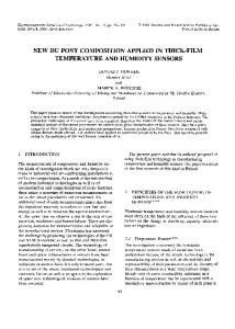
Digital Temperature and Humidity Sensor AM2320 Product Manual
Product Features:
Ultra-small size
Super cost-effective
Ultra-low voltage operation
Excellent long-term stability
Standard I2C and single-bus output
For more information, please visit: www. aosong .com
1. Product overview Temperature and humidity combined sensor AM2320 digital temperature and humidity sensor is a digital signal output has been calibrated. Using special temperature and humidity acquisition technology, ensure that the product has a very high reliability and excellent long-term stability. Sensor consists of a capacitive moisture element and an integrated high-precision temperature measurement devices, and connected with a high-performance microprocessor . The product has excellent quality, super fast response, strong anti-interference ability, very high property price rate. AM2320 communication using a single bus, two communication modes standard I2C. Standard single-bus interface, the system integration becomes easy and quick. Ultra-small size, low power consumption, signal transmission distance up to 20 meters, making all kinds of applications and even the most demanding applications the best choice. I2C communication using standard communication sequence, the user can directly linked to the I2 C communication bus without additional wiring, simple to use. Two communication modes are used as humidity, temperature, and other digital information directly CRC checksum temperature-compensated output, users do not need to calculate the secondary digital output, and no need for temperature compensation of the humidity, temperature and humidity can be accurately information. Two communication modes are free to switch, the user can freely choose, easy to use, wide range of applications. 4 lead product, easy connection, special packages according to user needs and provide.
2. Applications HVAC, dehumidifiers, testing and inspection equipment, consumer goods, automotive, automation, data loggers, gas stations, home appliances, humidity control, medical, and other relevant humidity measurement and control.
3. Product Highlights Completely interchangeable, low-cost, long-term stability, relative humidity and temperature measurement, long distance signal transmission, the digital signal output, precise calibration, low power consumption, standard single-bus digital interface standard I2 C bus digital interface, communication free choice.
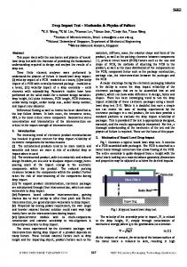
4. Dimensions (Unit: mm)
-1-
Figure 1 : AM2320 every inch form factor
External Interface: 1: VDD 2: SDA 3: GND 4: SCL
5. Sensor performance 5.1 Relative Humidity Table 1: AM2320 relative humidity performance table
parameter
condition
mi
typ
max
unit
n resolution Range Accuracy
0
99.9
25℃
Repeatability Interchangeability Response time
%RH
±3
%RH
±0.1
%RH
Completely interchangeable 1/e(63%)
Sluggish Drift
%RH
0.1
Typical
>=1; } } } return crc; } 8.2.4 I 2 C Communication Timing AM2320 sensor I 2 C communication, although according to the standard I 2 C communication sequence, but must follow our communication protocols and communication timing requirements, in order to accurately read the sensor. In strict accordance with the communication protocol and timing, please read the design. ◎I 2 C Read full Timing Example Figure 14 shows the read sensor when the full sample and write a special time requirements, in strict accordance with the requirements of the special time to read and write, otherwise it will appear unreadable sensors or incorrect data and so on. Several timing diagram special needs attention, the time requirements detailed in Figure; host communication from beginning to end, for a maximum of 3S.
2
Figure14: I C sensors read the complete example of fig - 15 -
◎I 2 C read and write timing decomposition Sensors read or write, you must follow these three steps, otherwise it will not communicate or can’t read the correct data: Step one: Wake Sensor In order to reduce the humidity sensor errors caused by self-heating, the sensor in a non-working state, dormant, so to read the sensor must wake sensor to transmit commands to read and write, otherwise the sensor will not respond. It should be noted that, in the wake sensor, I 2 C address is sent, the sensor does not respond to ACK, but the host must send back an ACK clock verify that the ninth SCL clock signal. Wake sensor operation is following instructions: After the host sends a start signal is applied to the starting address, wait for sometime (waiting time of at least 800 μs, the maximum 3ms; such as host hardware I 2 C, you do not need to wait for the hardware I 2 C will automatically wait), and then sends a stop signal. Namely: the starting signal +0 xB8 + wait (> 800us) + stop signal timing diagram shown in Figure 15.
Figure 15: Wake Sensor
Step two : Send the read command or send written instructions After the wake AM2320 sensors, can be fully in accordance with the standard read and write timing I 2 C, and the maximum speed supported 100Kb / s. Read the temperature and humidity of example, as shown in Figure 16. The host sends commands to: START +0 xB8 (SLA) +0 x03 (function code) +0 x00 (starting address) +0 x04 (register length) + STOP
Figure 16: sending a read command example temperature and humidity
Steps three : To return the data read or confirmation signal Send read / write command, the host is required to wait at least 1.5ms, and then sends a read timing, reads return data example shown in Figure 17; must be noted that, when you read the data, issued after the completion of I 2 C address, wait at least 30μs and then sent over the next serial clock, reading data, or communication error occurs. - 16 -
Figure 17: Read the sample temperature and humidity values
Host read back the data as follows: 0x03(Function Code)+0x04(data length)+0x03(high humidity)+0x39(low humidity) + 0x01 (high temperature) +0x15(low temperature)+0xE1(CRC checksum low byte) + 0xFE (CRC checksum high byte); Therefore: 0339H = 3×256 +3×16 +9 = 825 => humidity = 825÷10 = 82.5% RH; 0115H = 1×256 +1×16 +5 = 277 => temperature = 277÷10 = 27.7 ℃ These three steps can be completed by the sensor reads all registers, a write operation (the user can write registers, only five, namely the status register, register four users, while the status register can only be written separately, otherwise it will error) ; the user in the design, follow these three steps must be fully read and write. After sending the sensor data, trigger a temperature and humidity measurements; After the measurement is completed, the recording temperature and humidity values, then completed a communication, the sensor automatically goes to sleep; therefore, as long unread sensors continuously read the second sensor, in the second reading of the temperature and humidity back to the latest value (minimum interval of continuous reading 2S). 8.2.5 Peripheral read flowchart AM2320 read I2 C sensor schematic flow diagram shown in Figure 18, we also provide sample code reads C51, need to download the client, please visit our website (www.aosong.com) associated download, this manual does not provide code instructions.
- 17 -
2
Figure18: The I C read sensor flowchart 2
Tables Table 1: I C_MODBUS communication protocol summary table
2
Read Bus Description: I C address is 0xB8; access a maximum of 10 registers; Time to read a communication bus for a maximum of 3 S. Sensor data are added each time you return the CRC, the user can choose not to read the CRC Read sensor frame format: Host frame format: (SLA + W) + function code (0x03) + start address + number of registers From the machine frame format: function code (0x03) + data length + return data + CRC Write sensor frame format: Host frame format: (SLA + W) + function code (0x10) + + start address register number + save data + CRC From the machine frame format: function code (0x03) + start address + number + CRC register AM2320 sensors register list: Register
Addr
Register
Addr
Register
Addr
Register
Addre - 18 -
information
ess
information
ess
information
ess
informatio
ss
n High humidity Low humidity
High temperatur e Low temperatur e
0x00
Model High
0x08
0x01
Model Low
0x09
0x02
The version number
0x0A
0x03
Retention
0x04
Retention
0x05
Retention
0x06
Retention
0x07
Device ID (24-31) Bit Device ID (16-23)
0x0B
Users register a high Users register a low Users register 2 high Users register 2 low
0x10
Retention
0x18
0x11
Retention
0x19
0x12
Retention
0x1A
0x13
Retention
0x1B
0x0C
Retention
0x14
Retention
0x1C
0x0D
Retention
0x15
Retention
0x1D
Device ID (0-7) Bit
0x0E
Retention
0x16
Retention
0x1E
Status Register
0x0F
Retention
0x17
Retention
0x1F
Bit Device ID (8-15) Bit
Status Register Definition: Bit7-Bit0 bit reserved; Temperature Format: Temperature highest bit (Bit15) is equal to 1 indicates a negative temperature, the temperature highest bit (Bit15) is equal to 0 indicates a positive temperature; temperature in addition to the most significant bit (Bit14 ~ Bit0) indicates the temperature sensor string value. Temperature sensor value is a string of 10 times the actual humidity value; Write Sensor: For users to write register (0x0F ~ 0x13); prohibit write other registers and status registers can only be written separately. Reader sample: Function
Functi
Start
on
addres
Code
s Send:(SLA+W)+0x03+0x00+0x04
Read the temperature and
0x03
0x00
humidity Read the temperature Read humidity
Reading Device Information Write Status Register
Frame data content
Return:0x03 +0 x04 + humidity + high + low temperature and humidity high temperature low + CRC
0x03
0x02
0x03
0x00
Send:(SLA+W)+0x03+0x02+0x02 Return:0x03+0x02+High temperature + low temperature+ CRC Send:(SLA+W)+0x03+0x00+0x02 Return:0x03+0x02+High humidity+ Low humidity + CRC Send:(SLA+W)+0x03+0x08+0x07
0x03
0x08
Return:0x03+0x07+Model (16) + version number (8) + ID (32-bit)+CRC
0x10
0x0F
Send:(SLA+W)+0x10+0x0F+0x01+0x01+0xF4(Low)+0xB7(High) Note:Function code + register start address + register number - 19 -
+ save content+ CRC Return:0x10+0x0F+0x01+0xB4(Low Byte)+0x35(High Byte) Note:Function code + number + register start address register+ CRC Write a user registers a
Send:(SLA+W)+0x10+0x10+0x02+0x01+0x02+0xC0+0x92 0x10
0x10 Return:0x10+0x10+0x02+0xFC+0x04
Note: SLA = I2C address 0xB8. Table CRC parity bit, CRC was 16, the low byte first, high byte。 Return error code: 0x80: not support function code 0x81: Read an illegal address 0x82: write data beyond the scope 0x83: CRC checksum error 0x84: Write disabled.
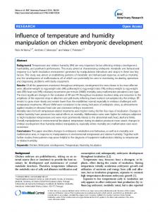
8.3 Single bus communication (ONE-WIRE) 8.3.1 Single bus typical circuit Connection with the AM2320 microprocessor typical application circuit shown in Figure 19. When single-bus communication mode, after pulling the SDA microprocessor I / O ports are connected. Single bus communication Special Instructions: 1. A typical application circuit recommended cable length shorter than 30 meters with a 5.1K pull-up resistor when greater than 30 meters when the pull-up resistor to reduce the actual situation. 2. 3.3V voltage supply is recommended when the cable length is not greater than 1m. Otherwise, line drop may cause the sensor communication error. 3. The minimum interval of the read sensor 2S; reading interval is less than 2S, temperature and humidity might result in denial or communication is unsuccessful and so on. 4. Temperature and humidity values are read out every last measurement result, want to get real-time data, the need to continuously read twice, repeatedly suggested reading sensor, and each sensor reading interval greater than 2 seconds to obtain accurate data.
Figure 19: AM2320 single bus typical circuit
8.3.2 Single bus communication protocol ◎ Single Bus Description - 20 -
AM2320 device uses a simplified single-bus communication. Single bus that only one data line, the data exchange system, the control by the data line is completed. Device (microprocessor) through an open-drain or tree-state port is connected to the data line to allow the device when not transmitting data to release the bus, and let other devices use the bus; single bus usually requires an external 5.1kΩof approximately pull-up resistors, so that when the bus is idle, the state is high. Because they are master-slave structure, only when the host calls the sensor, the sensor will be answered, so the host access to the sensor must strictly follow the sequence of a single bus, if there is a sequence of confusion, the sensor will not respond to the host. ◎Single bus transfer data definitions SDA and AM2320 microprocessors for communication and synchronization between using single bus data format, a 40-bit data transfer, high first-out. , The communication format specific communication sequence shown in Figure 20 are shown in Table 9.
Figure 20: AM2320 single bus communication protocol Table 9: AM2320 communication format Name Start signal Response signal Data Format
Humidity
Single bus format definition The microprocessor data bus (SDA) low period (at least 800μs)
[1]
, to prepare the data notification sensor
Sensor data bus (SDA) low 80μs, 80μs followed by a high signal in response to the initial host Upon receipt of the host start signal from the data bus disposable sensor (SDA) string of 40-bit data, the high first-out Humidity resolution is 16Bit, the previous high; strings out of the humidity sensor is 10 times the actual humidity values. Temperature resolution is 16Bit, the previous high; sensor string temperature value is 10 times the actual temperature value;
Temperature
Temperature highest bit (Bit15) is equal to 1 indicates a negative temperature, the temperature highest bit (Bit15) is equal to 0 indicates a positive temperature; In addition to the temperature of the highest bit (Bit14 ~ Bit0) indicates the temperature value.
Parity bit
Parity bit = humidity high temperature + humidity + high + low temperature low
[1] For details, see 7.3
◎ Single bus data sample calculation Example 1: 40 of the received data: 0000 0010 1001 0010 0000 0001 0000 1101 1010 001 High humidity 8 Low humidity 8 High temperature 8 Low temperature8 Parity bit Calculated as follows: 0000 0010+1001 0010 +0000 0001+0000 1101= 1010 0010 (Parity bit) Receive data is correct: Humidity:0000 0010 1001 0010 = 0292H (hex) = 2×256 + 9× 6 + 2 = 658 => Humidity = 65.8% RH - 21 -
Temperature:0000 0001 0000 1101 = 10DH (hex) = 1×256 + 0×16 + 13 = 269 => Temperature = 26.9 ℃ ◎ Special Instructions: When the temperature is below 0 ℃ temperature data for a top position. Example One: -10.1 ℃ expressed as 1,000,000,001,100,101 Temperature: 0000 0000 0110 0101 = 0065H (hex) = 6×16 +5 = 101 => Temperature = -10.1 ℃ Example Two: The received data 40: 0000 0010 1001 0010 0000 0001 0000 1101 1011 0010 High humidity 8 Low humidity 8 High temperature 8 Low temperature8 Parity bit Calculated as follows: 0000 0010+1001 0010 +0000 0001+0000 1101=1010 0010≠1011 0010 (Parity error) The received data is not correct, give up, again receiving data. 8.3.3 Single-bus communication timing Hosts (MCU) sends a start signal (data bus SDA low for at least 800μs) After, AM2320 transition from sleep mode to high-speed mode. After completion, the master start signal, AM2320 transmit a response signal, the data sent from the data bus 40Bit SDA serial high byte is transmitted first; data is sequentially transmitted high humidity, low humidity, high temperature, low temperature, the parity bit , sent a message to trigger the end of data collection, collecting sensor automatically transferred to the end of the sleep mode until the next traffic coming Detailed timing signal characteristics are shown in Table 10, a single bus communication timing diagram shown in Figure 21.
Figure 21: AM2320 single bus communication timing
Note: The temperature and humidity data from the AM2320 host always read the previous measurement, the measurement interval twice as long, please read twice in a row is the second time in the real-time temperature and humidity values, while two read take a minimum interval 2S. Table 10 : single bus signal characteristics Symbol
Parameter
min
typ
max
unit
T be
Host starting signal low time
0.8
1
20
ms
T go
Host Bus release time
20
30
200
µS
T rel
Response time low
75
80
85
µS
T reh
Response time high
75
80
85
µS
T low
Signal "0", "1" low time
48
50
55
µS
T h0
Signal "0" High Time
22
26
30
µS
T h1
Signal "1" High Time
68
70
75
µS - 22 -
T en
Sensor releases the bus time
45
50
55
µS
Note: To ensure quasi-sensor indeed communication, the user reads the letter when number, strictly in accordance with table 10 and the parameters in figure 21 program design. 8.3.4 Peripheral reading step example Communication between the host and the sensor reads the data can be done through the following three steps. Step One: AM2320 after power (power after AM2320 2S to wait to cross the unstable state, during the reading device can not send any commands), test environment temperature and humidity data, and record the data, then the sensor automatically transferred to a dormant state. The SDA data line AM2320 by resistance and pulling high has been to maintain a high level, then the AM2320 SDA pin is in the input state, always detect external signals. Step Two: Microprocessor I / O is set to output, while the output low and low retention time can’t be less than 800us, typical values are pulled 1MS, then the microprocessor I / O is set to enter the state, the release of the bus, Since the pull-up resistor, the microprocessor I / O data lines that AM2320 the SDA also will go high, and so the host releases the bus, AM2320 sends a response signal, the output low as 80 microseconds response signal, followed by 80 microsecond high output peripheral is ready to receive data notification signal transmitter 22 shown in fig.
Figure 22: Single-bus timing diagram decomposition
Step Three: AM2320 After sending the response, followed by a continuous serial data bus SDA data output 40, the microprocessor 40 receives the data according to I / O level changes. Bit data "0" in the form: low high 50 microseconds plus 26-28 microseconds; Bit data "1" format: LOW HIGH plus 70 microseconds 50 microseconds; Bit data "0", the bit data "1" signal format shown in Figure 23.
- 23 -
Figure 23: Single-bus timing diagram decomposition
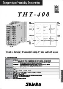
Data bus SDA AM2320 output 40-bit of data , the continued output low 50 microseconds after the entry into the state, due to the pull-up resistor attendant goes high. Meanwhile AM2320 retest internal temperature and humidity data, and record data, test recording ends, the micro controller automatically goes to sleep. Only after receipt of the start signal micro controller host, only to re-awaken the sensor, enter the working state. 8.3.5 Peripheral read flowchart AM2320 sensor reads a single bus flowchart diagram shown in Figure 24, we also provide sample code reads C51, need to download the client, please visit our website (www.aosong.com) associated download, this manual does not provide code description. On the sensor initialization Reading device sends a start signal No response signal Release the bus waiting for the sensor response signal There are a response signal Continuous reading device to read 40 data Parity error Data validation Correct parity Update temperature and humidity values Wait (fixed acquisition cycle) No Fixed acquisition time to? Yes
Figure 24: Single-bus read flowchart
9. Application Information 1. Work and storage conditions The proposed scope of work may result in up to 3% RH temporary drift of the signal. Return to normal working conditions, the sensor calibration status will slowly recover. To speed up the recovery process can be found in "recovery process." The use of the product will accelerate the aging - 24 -
process for a long time under abnormal operating conditions. Avoid placing components on a long-term condensation and dry conditions and the following environment. A, salt spray B, the acid or oxidizing gases such as sulfur dioxide, hydrochloric acid Recommended Storage Environment Temperature: 10 ~ 40 ℃ Humidity: 60% RH or less 2. Effects of exposure to chemical substances Capacitive humidity sensor sensing layer will be disturbed chemical vapors, chemical diffusion layer in the sensor may cause drift and measurement sensitivity. In a clean environment, slowly release contaminants out. The recovery process described below to accelerate the process. High concentrations of chemical pollution can cause damage to the sensor sensing layer completely. 3. Temperature Effect Relative humidity of the gas, is largely dependent on temperature. Therefore, when measuring the humidity should be possible to ensure that the humidity sensor works at the same temperature. If you share a printed circuit board with electronic components heat released in the sensor should be installed as far as possible away from the electronic components, and installed at the bottom of the heat source, while maintaining a well-ventilated enclosure. To reduce the thermal conductivity sensor and a copper plating layer of the printed circuit board should be as minimal other portions, and leaving a gap between them. 4. Light effects Prolonged exposure to sunlight or strong ultraviolet radiation, will reduce performance. 5. Recovery process Placed under extreme operating conditions or chemical vapor sensors, through the following process, you can return it to the state calibration. 2 hours at 45℃ and < 10% RH humidity conditions(Hong Gan); then at 20-30 ℃ and> 70% RH humidity under conditions remain more than 5 hours. 6. Wiring Precautions Affects the communication quality of the signal wire distance and communication quality, we recommend using a high quality shielded cable. 7. Soldering Information Manual welding, at a temperature of 300 ℃ maximum contact time must be less than 10 seconds. 8. Product upgrades For details, please consult our technical department.
10. License Agreement Without the prior written permission of the copyright holder, shall not in any form or by any means, whether electronic or mechanical (including photocopying), for any part of this manual may be reproduced, nor may its contents be communicated to a third party. The contents are subject to change without notice. Aosong Electronics Co., Ltd. and the third party has a proprietary software, the user may use only the signing of a contract or license the software. - 25 -
11. Warnings and personal injury Do not use this product as safety or emergency stop devices, as well as due to the failure of the product could result in personal injuries to any of the other applications. The product shall not apply unless there is a particular purpose or use authorization. Before installation, handling, use or maintenance of the product to the reference product data sheets and application notes. Failure to comply with this recommendation, that may result in death or serious injury, the resulting company will not be liable for all damages in personal injury and death, and thus exempt from corporate managers and employees and affiliated agents, distributors providers and any other claims that may arise, including: a variety of costs, compensation costs, legal fees and so on.
12. Quality assurance The company provides a period of 12 months (one year) quality assurance (calculated from the date of shipment from) their direct purchasers of the product. Data sheet of the company published the technical specifications of the product shall prevail. If the warranty period, the product is proved to be defective quality, the company will provide free repair or replacement. Users must satisfy the following conditions: ① The product is found defective within 14 days written notice to the Company; ② The product should be returned to the purchaser to pay the company; ③ the shelf life of the product should. The company only for those applications where the product meets the technical conditions arising from defective product. Company for its products in those particular applications without any guarantee, warranty or written statement. The company applied to the product or its products reliability of the circuit does not make any promises.
- 26 -