(1968). 10. Miller, D., Przetworniki elektryczne wybranych wielkoci fizykochemicznych. WNT, Warszawa, Polska, (1974). 11. Romer, E., Miernictwo przemystowe.
Electrocomponent Science and Technology, 1981, Vol. 9, pp. 93-100 0305-3091/81/0901-0093 $06.50/0
(C) 1981 Gordon and Breach Science Publishers, Inc. Printed in Great Britain
NEW DU PONT COMPOSITION APPLIED IN THICK-FILM TEMPERATURE AND HUMIDITY SENSORS JANUSZ J. GONDEK Member IEEE and
MAREK A. WOJCICKI Instititute of Electronics University of Mining and Metallurgy ul. Czarnowie]ska 78, 30-054 Krak6w, Poland
This paper presents results of the investigations concerning thick-film sensors of temperature and humidity. Main criteria have been discussed and design programs computed by the ODRA computer in the Fortran language. The production techniques of the sensor have been described. Based on the results of the measurements and on the statistical analysis of the sensor parameters the authors have given characteristics of these sensors. They have given examples of their applicability and production perspectives. Sensors produced in Poland have been compared with similar devices made abroad. The authors have applied compositions prepared by Du Pont. This has been possible owing to the assistance of this well known American firm.
1.
INTRODUCTION
The present paper contains its authors’ proposal of using thick-film technology in manufacturing temperature and humidity sensors. The paper is a result of the first research of this kind in Poland.
The measurements of temperature and humidity are the kinds of investigation which are very frequently made in industrial and air-conditioning installations as well as in transportation. As a result of the introduction of modern industrial technologies as well as of automatization and computerization of entire factories there arises a necessity of numerous measurements as far as the above parameters are concerned. An additional need of such measurements arises also from the important necessity nowadays to save fuel and energy as well as to preserve the natural environment. At the same time we observe a rise in the cost of raw materials, machinery and human labour. There are also growing demands for miniaturization and reliability of the manufactured devices. Electronics has answered the challenge by producing the technologies of the LSI and VLSI monolithic as well as thin and thick-film superhybrids integrated circuits. The technology of manufacturing of sensors, on the other hand, cannot boast such great achievements as sensors have been manufactured mainly by classical technologies, in miniature versions at best. It is only in recent years that as a result of the above mentioned technological and economic factors as well as progress in the exploration of space new technological versions of sensors have been invented.
2. PRINCIPLES OF THE FUNCTIONING OF
TEMPERATURE AND HUMIDITY SENSORS2,3, 7-9 Electronic temperature and humidity sensors function most often on the basis of the influence of these two factors on the change in resistivity, capacity, dielectric loss or impedance. 2.1
Temperature Sertsors 2,9,1
The investigation concerning the resistance temperature sensors made of metal has been undertaken because of the simple technology in the manufacturing process as well as the stability and reproducibility of their parameters and the linearity of their characteristics in a wide temperature range. Metals with electron conductivity resistance as a function of temperature can be represented with a satisfactory approximation by means of such general 93
WOJCICKI
J.J. GONDEK AND M. A.
94
formulas"
RT R273(1 +
(1)
R T R273 RZy3(T- 273) where"
-
(2)
3
at temp. T and 273K temperature coefficient of resistance
RT, R273 -resistance
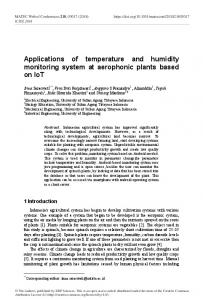
In classical metrology also such metals as platinum, copper and nickel are used and their relative temperature characteristics are given in Figure 1. R......_ 5,0
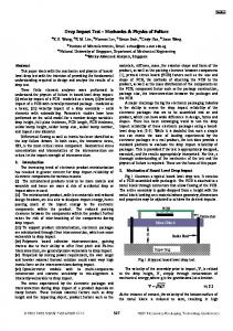
FIGURE 2 Construction of several miniature wire resistance temperature sensors.
Ni /;
.,/
4,0
Its value may practically range from a few seconds to a few minutes. New resistance temperature sensors made with the use of the thick-film technology are based on
Ba lco
the same important principles of their wire version.
// ,,’./ 3.
Relative temperature characteristics of resistive FIGURE sensing elements.
Figure 2, on the other hand, represents by way of example constructional variants of miniature wire sensors 11. Attention should be paid to their quite high thermal innertia, as the time constant of these sensors is given by means of this formula:
C uA where: C- thermal capacity of sensor u -coefficient of heat transfer from medium to resistor A -area of contact between sensor and medium
(3)
HUMIDITY SENSORS 2,9-11
The authors interest has also been focused on the capacitive humidity sensor. Its functioning is based on the change in impedance according to the amount of water contained in the dielectric under investigation. The space between the electrodes of the capacitor is filled with non-organic or organic hygroscopic dielectric whose resistance is contained within the limits 103 1018D and whose relative dielectric constant is 1 < ew < 70. The respective values for water, on the other hand, differ considerably and they are respectively S 2.105m, and e, 81. The impedance of this sensor is given by this formula:
Z
1
R + jo)RC
where: R- resistance defining losses in dielectric in o) pulsation of voltage supply in (Hz) C- capacity of sensor in (pF) Z- impedance of element in ()
(4) ()
Its loss is: tg6
oR C
(5)
We assume that the function of resistance for humid
THICK-FILM TEMPERATURE AND HUMIDITY SENSORS
dielectrics has the form: 10
4.
R=a.h-b
(6)
where: a, b constructional constants h relative humidity
1) The use as a substrate material of Polish alumina
(7)
where:
K- constructional constant of sensor dielectric permeability of vacuum
e0 e
relative dielectric constant of dielectric in sensor. The dielectric constant of sensor is: ed 1
+
ce
(8)
"Pw
-ded
with dimensions 50 30 0.55 mm and 0.9 um. 2) The use of DU PONT (USA) conductivity composition with numbers DP 9473, DP 9530, DP 9791, DP 9922. 3) A maximum use of area of the substrate.
96%
R
K’eo.e
e
CONSTRUCTIONAL AND TECHNOLOGICAL DESIGN OF A THICK-FILM TEMPERATURE SENSOR 2,4-6
The following criteria were adopted for the design:
The capacity of sensor is:
C
95
A120
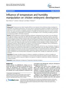
It was decided that a meander resistor, as shown in Figure 3, should be used. In order to calculate its parameters a computer program in the Fortran 1900 language for an ODRA type computer has been prepared. The program is shown in Figure 4.
where:
e,,- dielectric constant for dielectric and water c, d material constants Pw < 1- voluminal concentration of water ed,
After the transformation of formulas (4-6) we get a formula for replacement impedance Z and tg6 of a sensor containing the dielectric with water described in Refs. 9 and 10: a
Z b
(9)
+
h + jooKeoed
Cew
de,
Pw FIGURE 3. Topology of thick-film temperature sensor.
as well as a formula for its loss:
h
tga coKe( d
+
ce,,.
de
Pw
As one can notice, the formulas are very complicated because they contain numerous constructional and material constants together with balance humidity of the dielectric. Thus, for every new construction of this sensor one has to find its characteristic. An example of a capacitive humidity sensor is the construction invented by Jason. Its functioning is based on the measurement of the impedance of porous hygroscope layer. The sensor is an aluminum plate with an electrolytically deposited layer of aluminum oxide with high hygroscopicity. Aluminum oxide is covered by a permeable for humidity thin-film of evaporated gold which serves as the second electrode of the sensor.
Calculation of total resistance R for a meander resistor is not simple. There are a number of approximate methods used for calculation of similar topological constructions. In practice, however, the use of formulas resulting from these methods may lead to serious mistakes, especially in the case of designing resistors with low tolerance of resistance. A precise evaluation of total resistance for a meander resistor requires the use of a mathematical procedure based on transformation of conformal areas from which the most important one is Christoffel-Schwarz’s tranformation 1,6 leads to Jacobi’s first order elliptical integrals and to elliptical functions. This transformation serves as a base upon which the authors prepared the computer program for the thick-film temperature sensor. Christoffel-Schwarz’s tranformation transforms the area of a polygon together with its side in plane W into a semiplane and a real axis in plane Z. In this way it
J.J. GONDEK AND M. A.
96
wOJCICKI
"’"FIGURE 5 a) Fragment of bend in meander resistor, b) First transformation of Ch S. W’DLT4
w-OLT
N-(’-41//8,
f(s)
NO
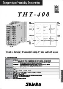
FIGURE 4 Computer program for calculating parameters of thick-film temp. sensor.
enables us to evaluate the resistance between arbitrarily placed contacts of resistors with various complicated configurations. In the case of meander resistors resistance of rectangular bends is defined by means of Christoffel-Schwarz’s transformation. An example of such bend is shown in Figure 5. Assuming that 1] > w] and > w we get the formula for the effective number of squares in a resistor bent at the right angle: n
ll + 12 14’
W
f(s) being given in the following formula:
the function
f(s)
(11)
2
-r
In
(
4S
s2+ 1
( 1) s2-
+s
s
arccos
s2- 1
sZ. + ’1
where:s Wa/Wz, andforw w we getf(s) 1,441. On the assumption thatw w w, which takesplace in the case of the design of this meander temperature sensor, formula (11) becomes (13): n
+ w
f(s)
(13)
The computer program show in Figure 4 evaluates an optimal width of a strip .W, with the assumption of total use of the surface of the substrate. Next, the program compares the evaluated total resistance R of a sensor for the width W with the assumed value R 0 with the precision O,lff2. An appropriate correction AW is added to or subtracted from value W in the feed-back loop. Next, the number of meanders N of the sensor is
TABLE No.
Compositions/Parameters
1,
R, [mf] [m]
2. 3. 4. 5. 6. 7. 8. 9.
R0
[mm] [mm] [W/mK] h [mm] w [mm] Is]
,
DP9791
DP9473
DP9922
DP9530
Au
Pd-Ag
Cu
Ni
1.3-2.6 15< 10 46 26.5 2.1 0.55 0.3 1.25
40-120 15-20 250 46 26.5 2.1 0.45 0.35 1.15
2-3 18 10 46 26.5 2.1 0.55 0.3 1.2
(12)
25-35 15 100 46 26.5 2.1 0.50 0.35 1.18
THICK-FILM TEMPERATURE AND HUMIDITY SENSORS
97
counted, with the assumption of total use of the surface of the substrate. The program also evaluates the time r after which the temperature sensor reacts with a change of its resistance, at a temperature change AT 2K. The evaluation of the parameters of the sensor is made for all the selected conductivity compositions. Value J is the index of the end of data. When J 1 the program is stopped. The results of the calculations are drawn up in Table I. Beside the solution given in Figure 3, also other topological constructions of temperature sensors have been prepared; they are shown in Figure 6. FIGURE 8 Illustration of inter-strip capacitance: a. Cross-section of structure, b. Structure after transformation.
n__
nan
FIGURE 6 Examples of topologies for thick-film temperature sensors
5.
CONSTRUCTIONAL AND TECHNOLOGICAL DESIGN OF A THICK-FILM HUMIDITY SENSOR 1,4,7
The principle of the measurement of humidity was based on the measurement of the electrical values C and tg6 of a specially designed film capacitor. A two-layer flat capacitor (Figure 7) was used; it was the so-called "comb" capacitor and its name is derived from the way it functions. Its capacity results from the existence of dissipated fields surrounding conductivity strips placed close to one another. dielectric film
\.
-