Digital Video Stabilization through Curve Warping Techniques Angelo Bosco1, Arcangelo Bruna1, Sebastiano Battiato2, Giuseppe Bella2, and Giovanni Puglisi2
Abstract — The widespread diffusion of hand-held devices with video recording capabilities requires the adoption of reliable Digital Stabilization methods to enjoy the acquired sequences without disturbing jerkiness. In order to effectively get rid of the unwanted camera movements, an estimate of the global motion between adjacent frames is necessary. This paper presents a novel approach for estimating the global motion between frames using a Curve Warping technique known as Dynamic Time Warping. The proposed algorithm guarantees robustness also in presence of sharp illumination changes and moving objects1. Index Terms —Video Stabilization, Dynamic Time Warping, global motion estimation.
I. INTRODUCTION Imaging devices offering video recording capabilities have gained significant popularity in the recent past. Frames resolution, movie-clips length and video quality are all factors of which users are becoming progressively more conscious. Hence, the request for high-quality video is increasing even when small portable devices, such as mobile phones, are concerned [1]-[3]. The assessment of video sequences involves many factors and the quality of the single frames is just one of the elements to be considered. Temporal incongruities such as compression artifacts occurring during scene changes, frame dropping and low frame rates are the major annoyances related to video quality perception. Nonetheless, even after reducing or eliminating the aforementioned problems, it is also necessary to consider the way in which video sequences are inherently acquired by the user. Video quality obtainable using small hand-held devices is obviously intrinsically affected by the unsteadiness of the user’s hands; therefore, without any correction, the acquired video will show unbearable jerkiness. Hence, the removal of unwanted camera vibrations is a fundamental element to be considered. Basically, two main approaches for removing nonintentional camera motion exist: mechanical and software based methods. Mechanical solutions consist in moving the 1 Angelo Bosco is with STMicroelectronics, AST, Imaging Team, Catania Lab, Italy (e-mail:
[email protected]). 1 Arcangelo Bruna is with STMicroelectronics, AST, Imaging Team, Catania Lab, Italy (e-mail:
[email protected]). 2 Sebastiano Battiato is with University of Catania - Italy (e-mail:
[email protected]). 2 Giuseppe Bella is with University of Catania - Italy. 2 Giovanni Puglisi is with University of Catania - Italy (e-mail:
[email protected]).
lenses to align frames onto the image sensor thus compensating for jerky motion. Similarly, another mechanical solution consists in moving the image sensor instead of lens. The software based stabilization is more cost-effective in that it relies exclusively on image processing techniques, avoiding the cost of mechanical moving parts. Software solutions generally require the estimation of the global motion between frames so that the opposite motion can be applied to counteract image shake and realign frames. Hence, the estimation of the global motion vector is a critical part of the system since this vector must correctly describe the amount of unwanted motion between frames. In [4] we proposed a method that derives the global motion between frames by analyzing the motion vectors obtained using block based motion estimation. This paper introduces a novel solution that estimates the global motion using a technique that finds matches between two curves known as Dynamic Time Warping (DTW)[5]. Our solution addresses the problem of stabilization in relation to the translational model [6][7]. The paper is organized as follows: sections II-III provide a description about the frame signatures and DTW. Section IV describes the proposed architecture. Section V ends the paper showing experimental results.
II. FRAME SIGNATURE CURVES Before giving full description of the DTW approach, we introduce frame signatures; they are simply obtained by processing the rows and the columns of each frame. The basic technique to compute frame signatures is known as integral projections [8]. In its simplest form, the method consists in summing up the pixel values of each row and each column generating two characteristic curves for each frame as depicted in Fig. 1. The value of each summation can be normalized to avoid too big values. Formally, given a frame F with m rows and n columns, two curves Cx and Cy are determined, according to the following equations (1): Cx ( j ) = C y (i ) =
1 m ∑ P(i, j ) , j = 1,..., n m i =1 n
1 ∑ P(i, j ) , i = 1,..., m n j =1
(1)
Cy(1)
Cy(i)
Y-Curve
For example, Fig.3 shows the CX-curves relative to two similar frames in which a large object moves in the center of scene. Under these conditions it is not easy to estimate the correct displacement between the curves: there is a large displacement in the center and very small displacement at the periphery.
Cy(m ) Cx(1)
Cx(j)
Cx(n )
X-Curve
Fig. 1. X and Y signatures for a frame with n rows and m columns.
The integral projections method allows estimating the global motion between two consecutive frames by shifting their CX-curves (CY-curves) in order to find the best alignment. The displacement used to determine the best match of the curves is representative of the global motion between frames. Figure 2 shows the CX-curves of two consecutive frames. The two test frames are very similar; hence the shape of the two curves is almost equal. The displacement of the two curves is caused only by the hand-shake of the user. By analyzing the amount of displacement between the two curves it is possible to determine the relative component of the global motion vector. XCurve
Fig.3.Critical curves for the integral projection method.
In order to properly cope with complex scenes, a more robust solution is necessary. Dynamic Time Warping (DTW) can provide the required level of robustness [5][9]. In general, the DTW method is used to warp and match generic sequences of numbers that can be viewed as curves in a proper coordinate system; the aim of DTW is to obtain a precise matching along the temporal axis, maximizing the number of point-wise matches between two curves. Formally, given two sequences X and Y of length n and m respectively (2):
X = x1 , x2 ,..., xi ,..., xn Y = y1 , y2 ,..., y j ,..., ym
(2)
A distance between the elements of the two curves is computed; the Manhattan difference can be used for efficiency in that it requires very little computational effort (3):
d (i, j ) = xi − y j
Column Number
Fig. 2. CX-Curves of two consecutive frames. The curves displacement in pixels gives the corresponding global motion vector component.
(3)
The computed differences are stored into a nxm matrix as defined in (4):
M (i, j ) = d (i, j )
(4)
A subset of the elements in M defines a warping path W (5): III. DYNAMIC TIME WARPING A significant limitation of the simple integral projection technique is that it cannot provide accurate results when the dynamics of the acquired scene become complex, as for example under fast varying illumination conditions and in presence of large moving objects. In these cases, the shape of the curves, even between consecutive frames, can be quite different and an accurate alignment becomes almost impossible to achieve.
W = w1 ,..., wl ,..., wK (5) Each element wl ∈W is a pair of indices (i, j) that associate an element of the X-series with an element of the Yseries.
The length K of the warping path is defined is such that (6):
max(m, n ) ≤ K < m + n − 1
(6)
The block diagram and data-flow of the algorithm are shown in Fig. 5. The process in then repeated for each pair of consecutive frames.
Clearly, many warping paths exist inside M, but we choose the one that minimizes the following functional (7):
⎛ DTW ( X , Y ) = min⎜ ⎜ ⎝
⎞ wl / K ⎟ (7) ∑ ⎟ l =1 ⎠ K
H-Signature Buffer
Current Frame
Extract Frame Signatures
H-Sig.
V-Sig.
WH
Warping Paths Analyzer
WV
GMVH
V-Signature Buffer
The elements of the matrix that are chosen for the best warping path define an association between the sequences X and Y, see Fig. 4.
DTW Warper Block
absGMVH
+
GMVV
+
Digital Stabilizer
absGMVV
Stabilized Frame
wK Fig.5. Block Diagram of the algorithm
wl
j
The point-wise matching associated to the horizontal signatures of two consecutive frames is illustrated in Fig. 6:
w1 i Fig. 4. A warping path example between two generic curves. The x(y)-axis spans the elements of the first (second) curve. Each marked item in the matrix represents a matching between a point of the first curve with a point of the second one.
The q-th element of the warping path wq(i,j) indicates that the i-th element of the first curve matches with the j-th element of the second curve.
IV. PROPOSED ARCHITECTURE The proposed method extracts the digital signatures from pairs of consecutive frames and warps them to find the best point-wise matching. The global motion information from frame t-1 to frame t is inferred by analyzing the warping parameters that maximize the point-wise matching. For any pair of frames t-1 and t, the horizontal and vertical digital signatures are extracted: Ht-1, Vt-1, Ht, Vt The process starts by storing the two current H/V-signatures in memory so that when the next frame carrying its own H/Vsignatures is processed, a DTW warping step is performed: DTW(Ht-1, Ht) DTW(Vt-1, Vt) Each warping step produces two warping paths: WH, WV, relative to the horizontal and vertical dimensions respectively.
Fig. 6. X-Curves of two consecutive frames having different illumination.
By analyzing how matching is distributed and how frequently it occurs, the components of the Global Motion Vector (GMVH, GMVV) are determined and added to the Absolute Global Motion Vector (AbsGMV) which is the motion computed in relation to the reference frame (9):
AbsGMVH = AbsGMVH + GMVH AbsGMVV = AbsGMVV + GMVV
(9)
Hence, the vector AbsGMV accumulates the global motion starting from the reference frame. Finally, the digital stabilizer block stabilizes the current frame according to the new AbsGMV. It is worth mentioning the fact that not all detected motion is unwanted; the user may intentionally move the device to perform panning. To this end, a low pass filtering of the detected motion is usually performed [10].
Integral Projection Error
V. EXPERIMENTAL RESULTS
3,5
• SET 1: sequences containing large moving objects; • SET 2: sequences showing fast illumination changes.
3 Error (pixel)
In order to confirm the validity of the proposed algorithm, a series of experiments have been performed comparing our approach with other digital stabilization techniques based on integral projections [8] and block matching [4]. The sequences used for the experiments were taken from two different sets:
2,5 2 1,5 1 0,5 0 1
4
7
10 13 16 19 22 25 28 31 34 37 40 43 46 49 52 55 58 61 64 67 70 73 76 Frame Number
Fig. 8. Integral projection estimation error along x (red) and y (green) axes for sequence 1. Block Matching Error
t ( y ) − GMVestt ( y ) Δt ( y ) = GMVtrue
2 1,5 1 0,5 0 1
4
7 10 13 16 19 22 25 28 31 34 37 40 43 46 49 52 55 58 61 64 67 70 73 76 Frame Number
Fig. 9. Block based estimation error along x (red) and y (green) axes for sequence 1.
(10) Dynamic Time Warping Error
t where GMVtrue (•) and GMVestt (•) are the real and the
estimated motion vector components respectively.
3
Error (pixel)
t (x ) − GMVestt (x ) Δt ( x ) = GMVtrue
2,5
Error (pixel)
The video sequences of both sets do not originally contain jerky motion. In order to scientifically measure the effectiveness of the proposed solution, hand-shake motion was artificially added to the original sequences by using a series of known global motion vectors representing typical real user hand vibrations. The difference between the true motion vector used to introduce jerkiness and the DTW-estimated motion indicates the precision of the proposed solution (10):
2
1
A. Experiment with large moving objects. 0 1 4
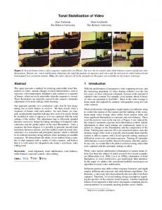
The first illustrated experiment is relative to a sequence from SET 1; it contains a crowd moving from right to left (Fig. 7). Figures 8 and 9 show that both integral projections and block matching approaches do not correctly estimate the motion vector components. On the contrary, the Dynamic Time Warping based solution generates a better estimate of the motion vector components (Fig. 8).
(a)
(b)
(c)
Fig. 7. A frame taken from a SET-1 sequence presenting large moving objects (sequence 1). The crowd is moving from right to left.
7 10 13 16 19 22 25 28 31 34 37 40 43 46 49 52 55 58 61 64 67 70 73 76
Frame Number
Fig. 10. Dynamic Time Warping estimation error along x (red) and y (green) axes for sequence 1.
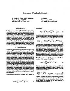
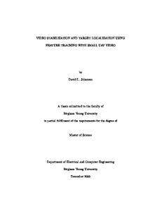
B. Experiment in fast changing illumination conditions. Our second illustrated experiment is relative to a sequence of SET-2. Fast illumination changes are exaggerated by dropping frames and increasing the speed at which the sun goes beyond the horizon (Fig. 11). The integral projection approach, finds incorrect matching between the frame signatures yielding inaccurate global motion estimation (Fig. 12). On the contrary, both Dynamic Time Warping and block matching based approaches, yield better results (Figg.13 and 14). In particular, it can be seen that no errors occurred along the x-direction.
technique also allows using only one frame buffer instead of two.
VI. CONCLUSIONS (a)
(b)
(c)
Fig. 11. A frame taken from a sequence with brightness variation in the scene due to the sunset (sequence 2).
Integral Projection Error 4,5 4 Error (pixel)
3,5 3 2,5
A new approach for the estimation of global motion between frames has been proposed. The solution can be incorporated in a system for video-stabilization for hand-held devices. The proposed technique is based on the Dynamic Time Warping techniques; hence it is robust in case of changing illumination conditions and moving objects which interfere with the shape of the frame signatures. Future work consists in optimizing the method in terms of speed and memory consumption.
2 1,5 1 0,5 0 1
4
7
Frame Number
Fig. 12. Integral projection estimation error along x (red) and y (green) axes for sequence 2. Block Matching Error 2,5
Error (pixel)
2 1,5 1 0,5 0 1
4
7 10 13 16 19 22 25 28 31 34 37 40 43 46 49 52 55 58 61 64 67 70 Frame Number
Fig. 13. Block matching estimation error along x (red) and y (green) axes for sequence 2.
DTW Error 2,5 2 Error (pixel)
REFERENCES
10 13 16 19 22 25 28 31 34 37 40 43 46 49 52 55 58 61 64 67 70
1,5 1
[1]
S. Battiato, A. Castorina, M. Guarnera, and P. Vivirito, “A global enhancement pipeline for low-cost imaging devices,” IEEE Transactions on Consumer Electronics, vol. 49, no. 3, pp. 670-675, August 2003. [2] A. Bosco, K. Findlater, S. Battiato, and A. Castorina, “Noise reduction filter for full-frame imaging devices,” IEEE Transactions on Consumer Electronics, vol. 49, no. 3, pp. 676-682, August 2003. [3] S. Battiato, A. Bosco, A. Castorina, and G. Messina, “Automatic image enhancement by content dependent exposure correction,” EURASIP Journal on Applied Signal Processing, vol. 12, pp. 1849-1860, 2004. [4] F. Vella, A. Castorina, M. Mancuso, and G. Messina. “Digital image stabilization by adaptive block motion vectors filtering,” IEEE Transactions on Consumer Electronics, vol. 48, no. 3, pp. 796-801, August 2002. [5] K. Wang, and T. Gasser, “Alignment of curves by dynamic time warping,” The Annals of Statistics, vol. 25, no. 3, pp. 1251-1276, 1997. [6] S. J. Ko, S. H. Lee, and K. H. Lee, “Digital image stabilizing algorithms based on bit-plane matching,” IEEE Transactions on Consumer Electronics, vol. 44, no. 3, pp. 617–622, August 1998. [7] S. Erturk, “Digital image stabilization with sub-image phase correlation based global motion estimation”. IEEE Transactions on Consumer Electronics, Vol. 49, No. 4, pp. 1320–1325, November 2003. [8] S. Piva, M. Zara, G. Gera, and C. S. Regazzoni, “Color-based video stabilization for real-time on-board object detection on high-speed trains,” Proceedings of the IEEE Conference on Advantage Video and Signal Based Surveillance (AVSS’03), pp. 299-304, 2003. [9] E. J. Keogh, and M. Pazzani, “Derivative dynamic time warping,” Proceedings of the First SIAM International Conference on Data Mining (SDM'2001), pp. 1-11, 2001. [10] S. Erturk, “Image sequence stabilization: motion vector integration (MVI) versus frame position smoothing (FPS),” Proceedings of the 2nd International Symposium on Image and Signal Processing and Analysis, pp. 266–271, 2001.
0,5 0 1
4
7 10 13 16 19 22 25 28 31 34 37 40 43 46 49 52 55 58 61 64 67 70 Frame Number
Fig. 14. Dynamic Time Warping estimation error along x (red) and y (green) axes for sequence 2.
The experiments proved that the integral projection technique suffers in presence of sharp brightness variations or large moving objects in the scene. Conversely, Dynamic Time Warping is robust enough and obtains results similar to, or better than, the block based approach. The proposed DTW
Angelo Bosco was born in Catania, Italy, in 1972. He received the degree in computer Science in 1997 at the University of Catania. He joined STMicroelectronics in 1999 in the Imaging Team (AST Catania Lab - Italy). His current research interests include noise reduction, digital image stabilization and tracking. He is author and co-author of various papers and patents in the image-processing field. Arcangelo Bruna received his Italian degree in Electronic Engineer in 1998 at the University of Palermo. First he worked in a telecommunication firm in Rome. He joined STMicroelectronics in 1999 where he works in the Advanced System Technology (AST) Catania Lab - Italy. His current research interests are in the areas of digital image processing from the physical digital acquisition to the final image compression. He is the author of several papers and
international patents on these activities. Giuseppe Bella received his Italian degree in Computer Science in November 2005 at the University of Catania, with a thesis about Digital Image Stabilization.
Sebastiano Battiato (M’05 – SM’06) was born in Catania, Italy, in 1972. He received the degree in Computer Science (summa cum laude) in 1995 and his Ph.D in Computer Science and Applied Mathematics in 1999. From 1999 to 2003 he leaded the “Imaging” team at STMicroelectronics in Catania. Since 2004 he works as a Researcher at Department of Mathematics and Computer Science of the University of Catania. His research interests include image enhancement and processing, and image coding. He published more than 80 papers in international journals and conference proceedings. He is co-inventor of about 15 international patents. He is reviewer for several international journals and has participated in many international and national research projects. He is a Senior Member of the IEEE. Giovanni Puglisi was born in Acireale, Italy, in 1980. He received his degree in Computer Science Engineer (summa cum laude) from Catania University, Italy, in 2005. He is currently Ph.D. student in the Department of Mathematics and Computer Science. His research interests include video stabilization and raster-to-vector conversion techniques.